Coherent Control of Polarized Neutron
Interferometry
by
Mohamed Osama Abutaleb
B.S. Physics, University of Maryland, College Park (2007) B.S. Mathematics, University of Maryland, College Park (2007) S.M. Electrical Engineering and Computer Science, MIT (2010) Submitted to the Department of Electrical Engineering and Computer
Science
in partial fulfillment of the requirements for the degree of
Doctor of Philosophy in Electrical Engineering
at the
MASSACHUSETTS INSTITUTE OF TECHNOLOGY
ARCIIVES
,MASSACHUSETTS INSTITUTE 07 -MCHN4OLOOYOCT 2
4
2012
L
BRARIES
September 2012©
Massachusetts Institute of Technology 2012. All rights reserved.Author ... v. v...
Department of Electrical Engineering and Computer Science
~/ .., - June 20, 2012 Certified by... ... G... David G. Cory Professor Thesis Supervisor
Accepted by ...
IU,
')
0
es7 A...
eslie A. Kolodziejski
Chairwoman, Department Committee on Graduate Students
Coherent Control of Polarized Neutron Interferometry
by
Mohamed Osama Abutaleb
Submitted to the Department of Electrical Engineering and Computer Science on June 20, 2012, in partial fulfillment of the
requirements for the degree of
Doctor of Philosophy in Electrical Engineering
Abstract
In this thesis, we describe two sets of experiments using a single crystal neutron interferometer. First, we explore applications of quantum information processing (QIP) to magnetic materials characterization using polarized neutron interferometry
(NI). We describe a split path spin-based interferometer geometry that uses the Bragg
interferometer to separate two paths where spin states are independently manipulated. The final measurement is made on the spin degree of freedom, so we observe spin-based contrast without a need for coherence in the path degree of freedom. This is difficult to achieve in a spin-echo interferometer because the two paths overlap, with only a time delay of one relative to the other.
Second, we present a design of a novel spin rotator design meeting the stringent space and temperature constraints of NI experiments. These passive devices use rem-nant magnetization FeCoV thin films and can be tuned to achieve arbitrary rotation of an incident neutron with known magnetization. Polarized neutron reflectometry measurements are reported for FeCoV monolayer films at thicknesses of 0.5 pm and
5.3 pm to characterize the depth-dependent vector magnetization in the films. Stray
field near such films is characterized to determine the effect on the neighboring neu-tron beam path. Contrast degradation due to the rotators is also discussed. Results for a prototype set of film rotators are presented showing a spin nutation > 900 from incident orientation. An architecture is presented for which any nutation angle can be achieved by tuning the separation of two composite film structures.
We also propose an experimental implementation of the deterministic quantum computation with one pure qubit (DQC1) model of quantum computation in NI. This circuit generates no entanglement, yet no efficient classical simulation is known or thought to exist. We present calculations showing a nonzero quantum discord in this implementation, as a means of quantifying other nonclassical correlations in addition to entanglement. All experiments were conducted at the Neutron Interferometer and
Optics Facility at the National Institute of Standards and Technology (NIST). Thesis Supervisor: David G. Cory
Acknowledgments
My research supervisor, Prof. David Cory, has served as a model of intuition, hard
work, and depth of understanding. I am grateful to have pursued my master's and doctoral degrees under his tutelage, and thank him for his support and belief in me throughout these five years. He has attracted an incredibly talented group of researchers that I have been privileged to work with, and I am thankful for him being a true advocate for his students. My NIST supervisor, Dr. Muhammad Arif, always supported my work and instilled confidence in me even when nothing seemed to work. I really could not have imagined a more enjoyable group to work in during
my Ph.D. research, and I am thankful for the collegial environment he fosters in the Neutron Physics Group. My academic advisor, Prof. Terry Orlando, has been a tireless advocate and continually supportive in navigating the many facets of my graduate program. I am grateful for his time and support through these years and for helping me navigate the difficult decisions I have faced throughout them. I am also thankful to Prof. Erich Ippen for serving on my doctoral and RQE committees, and for challenging me to compare and contrast my neutron optics work with light optics.
I thank all the professors who invested time and energy in teaching the challenging,
informative courses that I benefited from at MIT and the University of Maryland during my graduate years.
Two colleagues and friends stand out for providing the mentorship and guidance that most helped me develop as a researcher: Dmitry Pushin and Michael Huber. We have spent countless hours in the lab, at the board, and in the conference room, and my graduation today would not have been possible without their support and guidance. From Dima, I am especially grateful for showing a model of laboratory design and mathematical intuition. Michael's diligence in writing and software devel-opments were also very important models for me to learn from. I wish them both the very best in their professional careers, and hope to grow to mentor junior personnel in the same way they did for me.
I am also grateful to the entire Neutron Physics Group at NIST, among them Jeff Nico for arranging stimulating weekly seminars; Charles Clark for the many visitors he brought to the interferometry facility and instilling in me the confidence to present my work and answer questions; Andrew Yue for encouragement and many enjoyable conversations; Chandra Shahi for many laughs and always keeping positive attitude; Karl Schelhammer for being a great office mate and a source of encouragement; and Eli Baltic, David Jacobson, and Pieter Mumm for squeezing some exercise time into the hectic work schedule.
The collaborative, cooperative spirit of many colleagues was paramount to the completion of my experiments. Roger Pynn and M. Theo Rekveldt are gratefully acknowledged for use of Permalloy films used for my early passive film studies in NI. Jeff Lynn and Jeff Nico allowed me to borrow their neutron polarizers, without which my experiments may have been delayed an additional two years until our procurement finally came in. Tom Gentile's Helmholtz coils generated part of the guide field. Thanks to David Jacobson and Michael Huber for use of their Visual Basic scripts
for controlling the instruments. Thanks also to Rob Shankle and Eli Baltic for their excellent work in the machine shop fabricating many of the mechanical components that I designed.
I am also indebted to many colleagues for useful scientific discussions and expertise
in their respective fields, a few of which I mention here. Chuck Majkrzak is a valued collaborator who helped me with reflectometry studies crucial to this thesis and who graciously offered his time for many discussions about this thesis work. Sam Werner wrote a wonderful paper discussing the observation of Berry's geometric phase by neutron interferometry: our discussion on it was invaluable in differentiating between the many spin-dependent phases observed in interferometry. June Lau's expertise in magnetic domains was helpful in better understanding the thin film properties we observed, and helped with hysteresis measurements using her lab's BH-looper. Discussions with Brian Kirby and Brian Maranville on thin films are gratefully ac-knowledged. Guo-Xing Miao offered helpful advice on fabrication and domain wall formation. Troy Bornemann and Kevin Krsulich were always willing to let me discuss my ideas with them and offer a friendly challenge to my assertions. I shared helpful exchanges with Manny Knill and Gina Passante on the early conception of DQC1 measurements using interferometry. There are many others at NIST, IQC, and MIT to mention -but I am truly thankful for the opportunity to have interacted with each of them in these exceptional institutions.
I gratefully acknowledge support from a National Science Foundation Graduate
Research Fellowship for the first three years of my graduate career.
The encouragement and support of many friends at MIT helped me get through the long nights of studying, the cold winters, and the ups and downs of graduate school. Imran Shamim, Omair Saadat, Daniel Prashanth, Siddharth Bhardwaj, and many others - while our professional careers may now take us in many directions, I hope our friendships that began at MIT last a lifetime.
Many look to the fruits of their labor but forget the roots that made them possible, and I express my deepest gratitude to my family for raising me to value education, honor hard work, and respect others. Without your unwavering love, support, and confidence in me, I certainly would have never made it here. Though I can never repay my debt to you, I hope that I can live my life - in all of its facets - in a way that is a reflection of the values you instilled in my heart.
I thank God for giving meaning and purpose to life and for the opportunity to
Contents
1 Introduction
1.1 N eutron O ptics . . . .
1.2 Neutron Interferometry . . . .
1.3 Quantum Information Processing . . . .
2 Background
2.1 Neutron Scattering ...
2.2 Neutron Reflectometry . . . .
2.3 Phase Shift and Interferograms . . . .
2.4 Schr6dinger Picture of LLL Neutron Interferometer
2.5 Heisenberg Picture of LLL Neutron Interferometer
2.5.1 Path Degree of Freedom . . . .
2.5.2 Spin Degree of Freedom . . . . 2.6 Wavepacket Description of the Neutron . . . .
2.7 Neutron Spin Dynamics in a Magnetic Field . . . .
3 Instrumentation and System Design
3.1 NIST Center for Neutron Research . . . .
3.1.1 Neutron Interferometer and Optics Facility .
3.2 Experiment Preparation and Alignment . . . . 3.2.1 First Monochromator . . . .
3.2.2 Second Monochromator . . . . 3.2.3 Single Crystal Si Interferometer . . . .
17 18 20 22 25 . . . . 25 . . . . 26 . . . . 30 . . . . 34 . . . . 36 . . . . 36 . . . . 39 . . . . 40 . . . . 44 51 . . . . 51 . . . . 53 . . . . 59 . . . . 59 . . . . 59 . . . . 60
3.2.4 Helium-3 Detectors . . . . 64
3.2.5 Wavelength Measurements . . . . 66
3.2.6 Polarized Experiment Design . . . . 67
3.2.7 Spin Polarizer . . . . 69
3.2.8 Spin Analyzers . . . . 70
3.2.9 DC Coil Spin Rotators . . . . 71
4 Split Path Spin-Based Interferometry 73 4.1 Non-Remanent Permalloy Film Rotators . . . . 74
4.2 Experim ent . . . . 77
4.2.1 Theoretical Description . . . . 79
4.2.2 Measurements . . . . 83
4.2.3 Assorted Contrast Degradation Mechanisms . . . . 83
4.3 C onclusion . . . . 89
5 FeCoV Remnant Magnetization Spin Rotators 91 5.1 Neutron Spin Rotators . . . . 91
5.1.1 Previous Spin Rotators used in NI . . . . 93
5.1.2 Passive Magnetic Film Rotators . . . . 95
5.2 Single Film Remnant Rotators . . . . 96
5.2.1 D esign . . . . 97
5.2.2 Magnetic Hysteresis Loops . . . 100
5.2.3 Fabrication . . . . 104
5.2.4 Stray Field Characterization . . . 105
5.2.5 In-Plane Field Characterization via Polarized Neutron Reflec-tom etry . . . 110
5.3 Prototype Stacked FeCoV Film Rotators . . . . 115
5.3.1 Equivalent Unitary Rotation of Stacked Films . . . . 115
5.3.2 Neutron Transmission . . . . 116
5.3.3 Experimental Design . . . . 117
5.4 Contrast Degradation . . . .
5.4.1 Contrast Degradation due to Longitudinal Decoherence . . . .
5.4.2 Contrast Degradation due to Vertical Decoherence . . . .
5.4.3 Contrast Degradation due to Larmor Precession . . . .
5.4.4 Total Contrast Loss from Longitudinal, Vertical, and Spin
Co-herence Effects . . . .
5.5 Effect of the Substrate Layers on Attainable Net Rotations . . . .
5.5.1 Calculations for Prototype Fabrication Run . . . .
5.5.2 Experimental Considerations for Guide Field Strength and Si T hickness . . . .
5.6 Design of Spin Flippers . . . .
5.6.1 Two Spaced Identical Stacks . . . .
5.6.2 Anti-Aligned Stacks . . . .
5.7 C onclusion . . . . 6 Quantum Discord of the DQC1 Model in Neutron
6.1 Deterministic Quantum Computation with
One Qubit (DQC1) ... 6.2 Quantum Concurrence ... 6.3 Quantum Discord ... 6.4 Proposed Experiment . . . . 6.4.1 Computation of Concurrence . . . . 6.4.2 Computation of Discord . . . .
6.4.3 Quantum State Tomography . . . .
6.5 Sum m ary . . . . Interferometry 147 . . . . 148 . . . . 151 . . . . 152 . . . . 153 . . . . 155 . . . . 156 . . . . 157 . . . . 161 7 Conclusion
A Derivation of FeCoV Stack Effective Spin Rotation
163 165 119 122 124 128 135 137 138 139 140 140 142 143
List of Figures
1-1 Schematic of the spin-echo interferometer . . . . 21
1-2 Schematic of the Stern-Gerlach interferometer . . . . 22
1-3 Sketch of perfect crystal neutron interferometer and sample results . . 23
1-4 Laue scattering geometry . . . . 23
2-1 Elastic neutron scattering from a fixed nucleus . . . . 27
2-2 Specular reflection at interface of two bulk media . . . . 29
2-3 Interferometer with potential along one path II . . . . 31
2-4 Interferogram for empty interferometer with phase flag . . . . 34
2-5 LLL-type neutron interferometer . . . . 37
2-6 Perspective view of interferometer with coherence length axes labeled 44 2-7 Ideal interferometer with incident polarized beam and magnetic field region in Path I . . . . 49
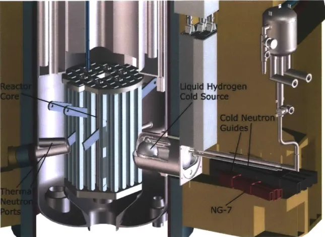
3-1 Illustration of reactor core and cold source . . . . 52
3-2 Diagram of the NCNR's thermal neutron instruments . . . . 53
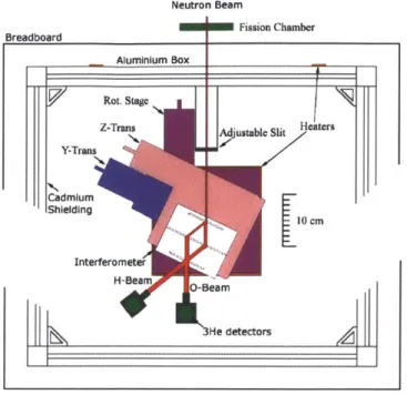
3-3 Diagram of the NCNR's cold neutron instruments in the Guide Hall 54 3-4 Artist's rendition of the Neutron Interferometer and Optics Facility 55 3-5 Scale drawing of interferometer and surrounding Al enclosure . . . . . 57
3-6 Phase and temperature stability over time . . . . 58
3-7 Photograph of the second pyrolytic graphite monochromator . . . . . 60
3-8 Rotation and tilt curves for second monochromator . . . . 61
3-9 Intensity vs. tilt of second monochromator tilt . . . . 62
3-11 Photograph of several interferometers used at NIST 3-12 3-13 3-14 3-15 3-16 3-17 3-18 3-19 3-20 3-21
4-1 Polarization vs. 10 pm Permalloy film tilt . . . . 4-2 Polarization vs. (a) translation, of downstream film,
two tilted 10 pm permalloy films . . . .
4-3 Circuit model of split-path spin interferometer . . .
4-4 Schematic of split-path spin interferometer . . . . . 4-5 Region designation for precession about guide field
(b) guide field for
4-6 Measurements for controlled-unitary experiment, good interferometer 4-7 Measurements for controlled-unitary experiment, bad interferometer 4-8 Circuit model of split-path spin interferometer with pre-measurement
sp in flip . . . . 4-9 Measurements for controlled-unitary experiment, good interferometer,
fixed phase flag . . . . 4-10 Measurements for controlled-unitary experiment, good interferometer,
varied phase flag . . . . 4-11 Measurements for controlled-unitary experiment, good interferometer,
fused silica wedge . . . . 4-12 Measurements for controlled-unitary experiment, bad interferometer .
5-1 Overhead schematic of NI with film rotator in path I . . . . Rotation alignment curve of interferometer .
Interferometer blade face scan . . . .
3He detector alignment . . . .
Beam uniformity image . . . . Wavelength measurement setup . . . . Wavelength measurement data . . . . Photograph of Mezei spin polarizer . . . . . Polarizer translation and rotation tuning . . Photographs of spin analyzing devices . . . . Spin flipper tuning for outer and inner coils
. . . . 6 4 . . . . 6 5 . . . . 6 6 . . . . 6 7 . . . . 6 8 . . . . 6 8 . . . . 6 9 . . . . 7 0 . . . . 7 1 . . . . 7 2 76 77 78 78 80 84 85 85 86 87 88 88 92 63
5-2 Past designs of neutron spin rotators inside the neutron interferometer 94
5-3 Schematic of remanent magnetization film rotator setup . . . . 97
5-4 Tuning of (a) zero remanence and (b) remanent magnetic films . . . . 99
5-5 Tuning of two zero remanence magnetic films to achieve a spin flip . . 99 5-6 Magnetization vs. applied field for 0.4 pum FeCoV and iron . . . . 101 5-7 B-H analyzer experiment setup . . . . 102
5-8 Magnetic hysteresis loops for (0.5, 2.0, 5.3) pim FeCoV films . . . . . 103
5-9 Easy axis magnetic hysteresis loops for (0.5, 2.0, 5.3) Pm FeCoV films 104
5-10 Photograph of fabricated 5.3 pm FeCoV coated Si wafers . . . . 105 5-11 Stray magnetic field from FeCoV rotators . . . 107 5-12 Experiment setup for magnetic field mapping measurements of FeCoV
film s . . . 108
5-13 Stray field Bs variation along Paths I and II due to FeCoV film . . . 109 5-14 Field computation geometry along beam paths in neutron interferometer110
5-15 Polarized neutron reflectometry setup . . . . 112
5-16 Scattering plane geometry for specular polarized neutron reflectometry 113 5-17 Polarized neutron reflectometry measurements of FeCoV thin films. . 114
5-18 Illustration of experimental setup for testing stacked FeCoV rotators . 117 5-19 Photograph of mounted prototype FeCoV films . . . . 118 5-20 P vs. FeCoV stack tilt for different stack sizes . . . . 120
5-21 P vs. FeCoV stack tilt for different stack sizes with large-angle rotator
calculations . . . 121
5-22 Contrast loss due to longitudinal decoherence with an uncompensated
Si sam ple . . . . 124
5-23 A neutron beam incident onto a tilted slab sample . . . 125
5-24 Vertical momentum distribution for the incident neutron beam . . . . 127
5-25 Contrast loss due to vertical decoherence, prototype and proposed
de-sign specifications . . . 128
5-26 Side view of tilted FeCoV film in interferometer . . . 129 5-27 Ideal interferometer with phase flag . . . 131
5-28 Ideal interferometer with film rotator in |-) path. . . . . 132
5-29 Contrast vs. film tilt from vertical for beam heights h from 1 to 8 mm
at 15 G and 5 G guide field . . . . 134
5-30 Larmor precession-dependent relative contrast as a function of tilt and
beam height . . . . 135
5-31 Cumulative contrast loss due to longitudinal, vertical, spin decoherence 136
5-32 Cumulative contrast loss due to longitudinal, vertical, spin decoherence
with compensated Si . . . . 137
5-33 Bloch sphere visualization of maximum attainable rotation . . . . 139
5-34 Stack separation vs. guide field and Si thickness . . . . 141
5-35 Nutation angle vs. stack separation for two example flipper specifications142
5-36 Nutation angle vs. guide field and tilt angle for anti-aligned stacks . . 143 5-37 Bloch sphere visualization of spin flip . . . . 144
6-1 The DQC1 circuit . . . . 149
6-2 Circuit model of proposed DQC1 experiment . . . . 153
6-3 Proposed DQC1 experiment for measuring nonclassical correlations . 154
6-4 Results from DQC1-equivalent circuit implementation by Rauch and
W erner . . . . 155
6-5 Quantum conditional entropy vs. a2 at representative 0 values . . . . 157
6-6 Nonclassical correlations generated by DQC1 algorithm with
controlled-Z rotation . . . . 158
6-7 Experimental setup for NI state tomography . . . . 160
List of Tables
1.1 Several Properties of the Neutron . . . . 18
2.1 Neutron Interaction Potentials and Phase Shifts . . . . 32
4.1 Fit results for proof-of-principle sample magnetization experiment . . 89
5.1 Magnetic Properties of Hysteresis Loops . . . . 102
Chapter 1
Introduction
In 1920, Rutherford postulated the existence of the neutron to explain the disparity between an element's atomic number and atomic mass [91]. A dozen years later the neutron was experimentally discovered by Chadwick [22]. The neutron plays an important role in many nuclear reactions, and knowledge of neutron behavior has been important in the development of nuclear reactors. Research using neutrons plays an important role in shaping our understanding of fundamental physics and furthering condensed matter research.
The neutron is an excellent probe of solid state physics for several reasons. First, the neutron wavelength at thermal energies is a few angstroms, closely matching the lattice spacing of most crystals; this allows for the study of crystal structure using neutron scattering, reflection, and diffraction [61]. Second, the neutron is associated with both a spin and a magnetic moment which allows for analysis of magnetic effects
[110]. Further, the neutron is electrically neutral allowing it to penetrate material.
Many elements that are difficult to observe using x-rays, such as hydrogen, are easily observed with neutrons. Certain atoms opaque to other radiation, such as lead or aluminum, are nearly transparent to neutrons. Studies of characteristic radiation em-anating from neutron capture can also be used to quantify trace amounts of elements in samples. A list of several important properties of the neutron is given in Table 1.1.
Table 1.1: Several Properties of the Neutron [99]
Property Value Unit
Mass, m 1.674927351(74) x 10-27 kg
Electric charge, q 0 e
Mean free lifetime, Tn 881.5(15) s
Spin, S 1/2 h
Magnetic moment, t -0.96623647(23) x 10-26 J/T
investigate interactions caused by all four fundamental forces of nature: strong, weak, electromagnetic, and gravitational. It is also used to study the Standard Model of particle physics by its weak decay into a proton, electron, and antineutrino. Neutron lifetime studies are important to development of the Big Bang theory, and experiments measuring the neutron electric dipole moment are important to exploring models beyond the Standard Model.
Neutron interferometry (NI), a subfield of neutron optics, traditionally has studied fundamental physics using neutron interactions caused by the strong, electromagnetic, and gravitational forces. NI is important to exploring a variety of quantum phenom-ena. Quantum information processing (QIP) offers a new framework for formulating
NI experiments that enriches the field. A recent example is the recent work by Pushin et al. in applying a decoherence-free subspace to a five-blade interferometer [85]. It
is anticipated that application of QIP principles will enhance the availability of NI in other fields such as solid state physics, materials characterization, and measurement of scattering lengths.
In this chapter, we present a broad overview of these fields and refer the reader to relevant resources. Neutron optics is reviewed in Section 1.1, neutron interferometry in Section 1.2, and quantum information processing in Section 1.3.
1.1
Neutron Optics
Neutron optics has played a key role in understanding fundamental physics and quan-tum mechanics. Chadwick's discovery of the neutron [22] was contemporary with the
notion of wave-particle duality proposed by de Broglie's relations [34]
h
A = (1.1)
my
relating a particle's associated wavelength A to its mass m and velocity v by Planck's constant h, and
E
f
= - (1.2)h
relating its frequency
f
and energy E. Neutron diffraction in crystals was postulatedby Elsasser in 1936 [39] subsequent to his earlier prediction on electron diffraction [38]. That same year, neutron diffraction was observed by Halban and Preiswerk [45] and by Mitchell and Powers [75]. In 1946, the interaction between neutrons and matter was described in terms of an index of refraction by Fermi and Zinn [41], analogous to light. Their description was successfully tested for neutron reflection from several different surfaces including graphite, aluminum, nickel, and copper [41]. Since the observation of neutron diffraction and reflection, the field of neutron optics has continued to grow, including the development of neutron interferometry. In 1994, the Nobel Prize in Physics was awarded to Shull and Brockhouse [1] for their work in neutron diffraction, inelastic neutron scattering, and neutron spectroscopy.
Fermi's work in the development of the first nuclear reactor in 1942 [40] was extremely important to the growth of neutron optics. Until then, neutron production had been limited to a two step process. First, an alpha particle would be produced
by the alpha decay of a heavy isotope such as 21oPo or 22 Ra. The emitted alpha
particle was then used in an (a,n) type reaction that produced fast neutrons with energies of around 1 MeV. High energy neutrons were slowed using a moderator with a large scattering cross section: multiple scattering within the moderator thermalizes the neutrons to an energy described by a Maxwell-Boltzmann distribution peaked at a moderator temperature. Early experiments used parrafin wax, a hydrogen rich material, as a moderator. This approach produces a low neutron flux; for example,
only 10 neutrons per minute were produced in Chadwick's experiments using 210po
The advent of the nuclear reactor spurred the availability of high intensity neutron sources. Research reactors now supply experiments with neutrons directly from the fission of 2"U. Spallation is another technique used at facilities such as the Spallation Neutron Source (SNS) at Oak Ridge National Laboratory, where a pulsed neutron beam is produced by bombarding a Hg target with 1 GeV hydrogen ions. The reactor facility for our research will be described further in this thesis in Section 3.1.
Further information on neutron optics can be found in several books on the subject such as those of Byrne [20] and Sears [95].
1.2
Neutron Interferometry
The first neutron interferometers was built by Maier-Leibnitz and Springer in 1962
[68]. This interferometer consisted of a single entrance slit and used a biprism for
beam recombination. In this configuration the beam separation is only - 60 pm, so it
is extremely difficult to perform measurements with a sample in only one beam path; further, the intensity in the original setup was quite low since it had an entrance slit of only 10 pm [62].
Mezei's paper in 1972 [73] on the spin-echo apparatus employed Larmor- and Ramsey-type interferometry. Here, the neutron's spin degree of freedom provides the basis for interference and there is no need for beam separation. The total energy of spin-up and spin-down neutrons is the same. Since the two spin states acquire different potential energies in a static magnetic field B, the kinetic energies must be spin-dependent to conserve total energy. The relation is given by
h2k2 h2k2
- ± |plB (1.3)
2m 2m
where k is the neutron wavevector in zero field, k± are the wavevectors corresponding to spin parallel and antiparallel to B, respectively, p is the neutron's magnetic mo-ment, and m is its mass. For a neutron traveling a distance 1 in the magnetic field,
B,
BO
BO
B,
n/2- turn
I/2-
tumPolarized incident beam Field reversal
Figure 1-1: Schematic of the spin-echo interferometer.
the phase difference
#(k,
1) between the spin-up and spin-down states is4(k, 1) = 21Ak ~lm. - ~B(1.4)
h2k
A schematic of the spin-echo interferometer is given in Fig. 1-1.
Another spin interferometer uses interfering beams that are separated by strong magnetic field gradients generated by Stern-Gerlach magnets. A schematic repre-sentation is seen in Fig. 1-2. A polarized beam passes through a r/2 spin rotator and is split into spin-up and spin-down components by the magnetic field gradient. After traversing a phase shifter and ir spin flipper, the beams are recombined and interference is observed. An early experiment performed by Sherwood, Stephenson, and Bernstein in 1954 successfully observed this interference for neutrons [96].
The first perfect crystal silicon interferometer was demonstrated in 1974 by Rauch,
Treimer, Bauspiess, and Bonse [87, 11]. The work built upon their past development of
perfect crystal interferometers for x-rays [15, 16, 14]. The experimental arrangement is diagrammed in Fig. 1-3. The interferometer is Laue-Laue-Laue type (LLL) and the experiment was performed at the 250 kW TRIGA-reactor of the Atominstitut in
Austria. An incident neutron beam is filtered to mean wavelength 2
A,
AA/A = 0.6%by a graphite monochromator. At each crystal blade, the neutron is scattered in the Laue geometry seen in Fig. 1-4: the crystal atomic planes from which the neutron scatters are perpendicular to the blade, and the scattered beams exit on the opposite side of the blade from the incident beam. The incoming beam is coherently split if
Analyzr
4- - Detector
Sample
% -e
Polarimr
Figure 1-2: Schematic of the Stern-Gerlach interferometer [82].
its wavelength A satisfies the Bragg condition
A = 2dsin6B (1.5)
where d is the atomic plane spacing and 0
B is the angle between the planes and the
incident beam.
The LLL interferometer is the most frequently employed type of neutron interfer-ometer, and the type used in this thesis. It is the functional equivalent of the optical Mach-Zehnder interferometer for light. It is the most versatile geometry since it offers a large path separation in a compact space. Other types of interferometers can be found in the review of Bonse and Graeff [13] and the book of Rauch and Werner [88].
1.3
Quantum Information Processing
Quantum information processing (QIP) offers a systematic approach to creating, con-trolling and measuring quantum coherence. Neutron interferometry can be used as a testbed for exploring quantum information processing in a mature, well-characterized experimental environment. Both the path degree of freedom and the neutron's spin degree of freedom are useful qubits.
from graphite [110] monochromotor Ad A A-cmsheet 0
bcm...
1 ~3000 * * * . . 0 S2000-0 forward -beam (0) 14~ W. * a * a 200 400 600 IP D m]M 800Figure 1-3: (left) Sketch of perfect crystal neutron interferometer, LLL-type. (right) Intensity vs. phase flag rotation for 0 and H beams. Contrast for these early experi-ments was only about 20%. Figure from [87].
Figure 1-4: Laue scattering geometry: a neutron beam coherently splits at the blade due to Bragg diffraction on the crystal atomic planes. The outgoing beams increase in width by approximately the thickness of the blade, called the Bormann fan effect. Illustration used with permission from [50].
The neutron interferometer offers several advantages as a testbed for QIP. The timescale is such that experiments can be modified between neutron counts. Projec-tive measurements are made with highly efficient 3He detectors (> 99%), offering a
different paradigm from weak measurements in spin ensembles. Further, only a single neutron wavepacket is in the interferometer at a time: that is, the interference we observe is the interference of the neutron with itself.
The application of QIP to NI allows for new classes of experiments and increased availability of the technique. Past work includes coherent approaches to phase con-trast neutron imaging [84], extending the measurement of the neutron vertical co-herence length [83], and introducing a quantum error correction code that protects neutron interferometers from the loss of contrast associated with mechanical vibra-tions [85].
Chapter 2
Background
In this chapter, we develop key tools that will be used in describing the experiments presented in this thesis. We begin with a brief review of neutron scattering in Sec-tion 2.1 and neutron reflectometry in SecSec-tion 2.2. Then we discuss phase shift and interferograms in neutron interferometer Section 2.3. Next, we develop a two qubit system description of polarized NI in both the Schr6dinger (Section 2.4) and Heisen-berg (Section 2.5) pictures. A one-qubit description was first developed by Pushin
[82] in describing experiments using the path degree of freedom. To discuss coherence
effects, we develop a wavepacket description of the neutron in Section 2.6. Finally, selected concepts from neutron spin dynamics are reviewed in Section 2.7. The review is by no means exhaustive and the reader is directed to relevant references through-out; in particular, neutron interferometry is rigorously developed in many articles and books [88, 95, 106].
2.1
Neutron Scattering
A detailed treatment of scattering theory is beyond the scope of the thesis. The
theory of scattering is covered in any graduate level quantum mechanics textbook. Neutron scattering in particular is developed in many books, including those of Sears
[95] and Byrne [20]. In addition to interferometry, neutron scattering is used in
of matter. Many intricacies of scattering theory can be ignored when considering low energy neutrons, an approximation valid for both the neutron interferometry and neutron reflectometry studies presented in this thesis.
Consider the elastic scattering of a neutron from a target nucleus, such that the total energy of the neutron is conserved. We momentarily ignore the magnetic inter-action of the neutron with the media and consider only its nuclear interinter-action. We describe a non-interacting neutron traveling in free space as a plane wave
10 (2.1)
where the wavevector k = ko + ky9 + k~2 and its position in space r =
+
y9 + z2.This description implies that the neutron extends infinitely in space; this is intuitively unappealing for our notion of a localized particle, but is remarkably accurate for many scattering applications. A notable exception is coherence effects in interferometry, so a wavepacket description is developed in Section 2.6 for that purpose. After scattering from the target, the resulting neutron wavefunction is a superposition of the incident plane wave and a spherically scattered wave
ikr-b eikr (2.2)
r
where b is the nuclear scattering length and 6 is the angle between the incident and scattered wave. The scattering length represents the interaction of the neutron with the nucleus, and the minus sign indicates that positive b corresponds to a repulsive interaction potential. The scattering length is a complex number, but the imaginary component is only important for nuclei with a high absorption coefficient and can be treated as real otherwise.
2.2
Neutron Reflectometry
Neutron reflectometry is a technique that is well suited to determine nanostructure and material properties of thick films and multilayers. Polarized neutron
reflectom-Spherically Scattered Wave Incident Wave k
'0
|q| 1
Targetsin
=
---
q
sin6=2
Ik|
4w
q
=
2ksin6
=
-
sin
0
Figure 2-1: Elastic neutron scattering from a fixed nucleus. Modified with permission from [49].
etry (PNR) is also sensitive to the magnetic properties of such devices. The spatial sensitivity of PNR arises because the neutron is charge zero yet possesses a mag-netic moment, allowing it to penetrate deeper into materials than charged particles and interact with atomic magnetic moments. Further, neutrons can be obtained with wavelengths comparable to interatomic distances. In this thesis, we use specular PNR to investigate the in-plane average of the vector magnetization depth profile along the surface normal of novel magnetic films. We briefly develop some tools to understand the data we present in this thesis; more detailed references are plentiful, including
[80, 69, 4, 112].
In Fig. 2-2, we diagram a neutron incident onto an interface of two bulk media. At the interface, the neutron will display reflection and refraction analogously to an electromagnetic wave. We can use the constructs of both quantum mechanics and classical optics to discuss its behavior. Again, we assume an elastic scattering process that can described by a time-independent Schr6dinger equation
I h V2 + V(r) J = E0. (2.3)
2mI
Outside of the material medium, the potential energy is effectively zero, so the total energy of the neutron
1 h2k2
E = -me 2 . (2.4)
2 0-2m
We assume that that matter can be described as a continuous distribution, allowing us to describe the medium consisting with atomic density N by potential energy
27rh2 27rh2
V = Nb= p (2.5)
m m
where b is the coherent scattering length and p -- Nb is the scattering length den-sity (SLD) of a monoisotopic medium. For media with multiple isotopes, the SLD generalizes to
M
p = Njbj (2.6)
j=1
where M is the number of distinct isotopes in the medium. Since the total energy is conserved in the elastic process, we can equate the kinetic energy of the neutron in vacuum with the total energy inside the material medium to obtain the wave equation
(V2 + k2 - 41rp)o = 0. (2.7)
Consider a neutron with wavevector ko incident onto a planar boundary between media 0 and 1 as diagrammed in Fig. 2-2. Here we are examining specular reflection, defined to have angle of reflection equal to angle of incidence. The refractive index at the boundary between two media is defined as
n = . (2.8)
ko
If the zero medium is taken to be vacuum, the index of refraction can be written as
n= 1 - Pi (2.9)
27r
ko ko
0000 no
kz= ko sin 0
Qz= 2kz = 41r sin OO/A
Figure 2-2: Specular reflection at interface of two bulk media of refractive indicies no and ni. The incident and transmitted waves are at the same angle 0 and the transmitted wave is at angle 01.
be zero. Most materials have n < 1 so neutrons are externally reflected from most
materials. The critical angle is defined as the maximum angle where total external reflection occurs,
cos Oc = -, (2.10)
no
based on Snell's law. With these definitions and the assumption that no = 1, we can
recast the wave equation (Eq. (2.7)) as
(V2 + kL2)0 = 0 (2.11)
where k = k1 = n1ko.
Thus far, we have only considered the nuclear interaction of the neutron with the nuclei of the medium. Throughout this thesis, we also employ the spin of the neutron to probe material properties and physical processes of interest. We develop some very basic constructs to aid in this discussion in Section 2.7.
2.3
Phase Shift and Interferograms
The neutron interferometer is a device that causes neutrons to exhibit wave inter-ference effects. The interferometer itself is a machined from a large, perfect crystal Si ingot, through a process described further in Section 3.2.3. The interferometer consists of three crystal blades affixed to a common base, as diagrammed in Fig. 2-6. When a neutron of wavelength A strikes the interferometer, the atomic planes in the blades diffract those neutrons which satisfy the Bragg condition
A = 2dsinOB (2.12)
where d is the atomic plane spacing and 0
B is the angle subtended by the incident
beam with respect to the atomic planes.
A simple schematic of the spatially separated paths of an interferometer, with a
potential V applied to one path, is given in Fig. 2-3. The phase a neutron wave-function acquires as it propagates through space and time is described by the path
integral [42]
<1(x, t) = 2J dt (2.13)
where the Lagrangian Y = p - v - de is the Lagrangian. Using v = ds/dt, then
D(x, t) p -ds - H dt. (2.14)
In the neutron interferometer, the measurement is sensitive to the phase difference between paths I and II of the interferometer,
A4b(x, t) = (Jp - ds - Jp1 - ds -J H dt - jH dt). (2.15)
It is important to note that at any given time, there is at most a single neutron in the interferometer. Thus, the phase AOp arises from self-interference of neutron.
Table 2.1 lists several neutron potentials and associated phase shifts as assembled
?
k
K
k
Path II
Source
Detector
Path I
Figure 2-3: Interferometer with potential V along path II which modifies its wave-function within the potential region [49].
relevance to the experiments reported in this thesis. The table highlights to one of the distinguishing characteristics of NI: it is a tool allowing measurements sensitive to the phase of the neutron state, not just its amplitude. It is also one of the best examples of macroscopic quantum coherence, with separation between the beam paths on the order of several centimeters.
We compute the phase shift from the Schr6dinger equation,
h
2k
2h
2K
2E + V (2.16)
2m 2m
where V is the optical potential of the interaction under study. For the nuclear inter-action, the optical potential of a given medium is given by the Fermi pseudopotential
V = 2bh2 Zb6(r) (2.17)
m
where b is the neutron scattering length for that medium. For a homogeneous mate-rial, the potential can be expressed as
27rh2
V = Nb (2.18)
m
Table 2.1: Neutron Interaction Potentials and Phase Shifts [88]
Interaction Potential Phase Shift Reference
Nuclear 27 2be6(r) -NbcAD Rauch et al. [87]
(1974)
Magnetic -p -B(r) i mAD Rauch et al. [90]
(1975)
Gravitation mg -r mimggAAsin(a) Collela et al. [30]
(1975)
Coriolis -hw(r x k) 27Wo -A Werner et al. [109]
(1979)
Aharanov-Bohm -- - B(t) tH Allman et al. [2]
(Scalar) (1992)
Aharanov-Casher -p - (v x E)/c itE -D Cimmino et al. [26]
(Schwinger) (1989)
Magnetic Josephson -p - B(t) ±Wt Badurek et al. [7]
(1986)
Fizeau N/A -NbcAD( -) Klein et al. [54]
(1981)
Geometrical (Berry) N/A Q/2 Wagh et al. [104]
(1997)
B: magnetic field strength
g: gravitational strength
A: normal area enclosed in coherent beams
a: angle between horizontal and area A
we = 0.727 x 10⁴s1: angular rotation velocity of the earth E: electric field
hw: energy transfer due to the time-dependent field B(t)
T: time during which B is turned on
wo, vx: velocity components of phase shifter, neutrons perpendicular to shifter surface Q: solid angle subtended by closed path on Bloch sphere
expressed as
V _ A2Nb A2Nb
E 27
Unlike photons, the index of refraction for neutrons in most materials is less than one. The phase shift caused by the nuclear potential is given by
<D(x) = hk -ds - hK -ds) (2.20)
= jkds - kn ds (2.21)
=
jkds
-jkds
-jANbds
(2.22)= -ANDb (2.23)
where D is the effective thickness of the material. This result is important to the study of neutron spin rotators that introduce material into the beam as discussed later in the thesis. A similar derivation yields the magnetic phase shift quoted in Table 2.1.
The phase shift is measured in an interferometer via an interferogram. The ex-perimental setup is diagrammed in Fig. 2-5. A control sample, called a phase flag, is placed intersecting both beam paths. For experiments described in this thesis, the control sample is 2 mm thick fused silica. Rotating the phase flag about its central axis parallel to 2 by an angle 6 varies the relative phase between the two beam paths and modulates the intensity at the detectors. The O-beam detector intensity becomes
Io = A + B cos (-2ANDbf (6) + #sam +
do)
(2.24)where A and B are constants, the first term inside the parenthesis is the phase shift caused by the flag,
#sam
is the phase shift caused by a sample, and 0 is the initial phase shift between the two paths, caused by a lack of perfect match between them.The phase shift due to the flag is
#flag
= -2ANDbf (6) wheresin(6) sin(OB)
f (6) cos2(OB)
o 1200-a. 1000-800 600 400 -- 200--2 -1 0 1 2
Phase Flag Rotation (0)
Figure 2-4: Interferogram for empty interferometer with phase flag. The bottom, red data correspond to the O-detector and the upper, blue data correspond to the H-detector. The contrast here is 80%.
is due to the geometry. From Eq. (2.24), we are able to determine the unknown phase shift due to a sample
#sam
from measurements at different phase flag rotation angles. Experimentally, larger fringe visibility yields better statistical precision of the result for#sam,
which is deduced from a sinusoidal fit of the data. A sample interferogram is reported in Fig. 2-4. Contrast is discussed further in Sections 2.4 and 2.6.We provide two descriptions of the neutron interferometer employed throughout this thesis: the Schr6dinger picture in Section 2.4 and the Heisenberg picture in Section 2.5.
2.4
Schrodinger Picture of LLL Neutron
Interfer-ometer
Historically, the theory of neutron interferometry has been described by two separate wavefunctions for each of the beam paths. In fact, this masks the beautiful coherence properties that this system presents. It is convenient to describe the state of the neu-tron as it propagates through the interferometer as a qubit (two-level system) using
Dirac notation. This also allows us to test codes developed in quantum information processing using the interferometer. We present this description in the Sch6dinger picture here and in the Heisenberg picture in Section 2.5.
The LLL neutron interferometer geometry is depicted in Fig. 2-5. A monochro-matic, collimated beam impinges upon the first blade of the perfect crystal interfer-ometer. We express the neutron state in terms of basis states labeled by the sign of
k2, the neutron momentum in the x-direction, as |+) and |-). The coordinate axes
are given in Fig. 2-6. The incident neutron state is 0o =
|+).
Any neutron satisfying the Bragg condition, Eq. (1.5), is coherently split into two beam paths by the first blade,|0i) = t+) + r--). (2.26)
where t and r are the complex amplitudes of transmission and reflection, respectively. Both are functions of
Ik
- kB , where k is the neutron wavevector and kB is the wavevector exactly satisfying the Bragg condition. Both t and r can be described by the theory of dynamical diffraction [88, 95].The second blade acts as another beam splitter, though we only retain the reflected wave in each case. A loss of intensity occurs but no information is lost. Renormalizing to unit intensity, the neutron state is written as
1
|@2) =
(rr*e1|I+)
+ treP2|_)) (2.27)where W1 and p2 are the phases accumulated by the neutron from the 1s to the 2n
blade on the 1+) and |-) paths, respectively. Interference occurs at the third blade and the outgoing neutron state is given by
1
10f) = [(tlr|2,i - tjr|2ei+2)|+) + (rlr|2
ei' + t|2r)ei+2|-](2.28)
where
#
1 and#
2 are the phases the neutron accumulates traversing the entire|+)
and|-) paths, respectively.
that exit along each path. The beam path corresponding to |+) has been labeled as 0-, C3-0-, and forward-beam in the literature;
|-)
is called H-, C2-, and deviated-beam. The O/H nomenclature is employed in this thesis. The path projection operatorsare written as Po -I +)(+ and PH = -)(-1. The detectors measure intensities
corresponding to the square modulus of the projected wavefunction,
Io = (@fIPol/f) (2.29)
- t|2|rJ4(1 - cos(#2 - #1)) (2.30)
IH = (f PH I'f) (2-31)
- [1t|4 +| r|6] + |t|2||r|4 cos(#2 - #
1) (2.32)
The contrast C of interference, the ratio of the amplitude of a sinusoid to its mean, is analogous to fringe visibility in light optics. For an ideal neutron interferometer, notice
Co = max(Io) - min(Io) = 1 (2.33)
max(Io) + min(Io)
CH - max(IH) - min(IH) r2t24 ±r (2.34)
H maX(IH) + min(IH) Jt4Jr2 _ Jr6'
In practice, interferometer contrast is lower than unity. This is due to practical imperfections in the interferometer crystal, neutron absorption, scattering, and en-vironmental disturbances. Early experiments observed contrast of just 20% [15] and the best interferometers report contrast between 80% and 90% [36].
2.5
Heisenberg Picture of LLL Neutron
Interfer-ometer
2.5.1
Path Degree of Freedom
Figure 2-5 illustrates the operation of a 3-blade, LLL-type neutron interferometer. The path degree of freedom is a good quantum number for the system; we label the
Figure 2-5: LLL-type neutron interferometer with incident neutron beam entering from left. The beam width increases at each blade by an amount approximately equal to the blade width, due to the Bormann fan effect introduced in Fig. 1-4. The phase flag is illustrated yellow and rotates about its central vertical axis.
two paths by the x-component of the neutron momentum k, as
+) (2.35)
0
0
|-) =(2.36)
The neutron is incident upon the interferometer in the 1+) state, and is coherently split via Bragg diffraction by the first blade, partially reflected by the second blade, and coherently recombined by the third blade before detection.
An ideal blade would operate analogously to a 50/50 beam splitter in light optics, also called a Hadamard operator. It is represented by
-1(1 1N
H = =K. (2.37)
reflec-tion, so we represent the real blade operator as a rotation between the two paths,
OB = (2.38)
r+ t_
where t± and r± represent the transmission and reflection coefficients for the |+) and
-) states, respectively. To correspond to a physical operation, 6B must be unitary;
this implies that for complex t and r, t = t+= -t* and r = r+ = r*. Further, to conserve neutrons we require that
|t|
2+|
r|2 = 1. Under these conditions, we writethe general blade operator
OB
=). (2.39)(r -t*)
This describes the action of the first and third blades. For the central blade, Bragg diffraction also occurs but only one beam remains in the interferometer. This results in a loss of intensity, but no loss of information. If we re-normalize for the lost intensity after the second blade, its action is analogous to a mirror:
0M
0
).
(2.40)=(1 0)
A control sample called a phase flag is placed in both beam paths to vary the relative
phase shift between them. The phase flag causes a phase shift in each beam path due to the neutron's interaction with the nuclear potential of the control sample. Its action is given by
es1 0
011 = ) . (2.41)
We can factor out the phase common to both paths since a global phase shift is undetectable; define the relative phase shift
4
= <D2 - <bi to express the operator as,The 3He detectors downstream of the interferometer act as projection operators on
the path degree of freedom, causing the neutron wavefunction to collapse into the |+),-) basis, 0 0
PO==
(1
0)
(2.43)
andPH
=H)H(
)
(2.44)
0 12.5.2
Spin Degree of Freedom
We denote the spin state in terms of a basis of its -eigenstates
) =
()(2.45)
0
and
0
4)=
.
(2.46)The neutron is incident in the unpolarized state |$o) =
.
Projection operatorsare realized experimentally by spin polarizers. We are able to select from both up-and down-states, 1 0
(PT
= (2.47) and 0 0 p = 01)(2.48)By convention, polarizers placed downstream the neutron interferometer are called
spin analyzers.
The spin magnetization orientation is manipulated by applying a magnetic field
an overall rotation by angle 0. For all experiments described in this thesis, B is time-independent. The operator describing this is given by
- Cos 0- inz sin ( -n -0nx) i
UR(O) = e-ioa--f/2 _ 2 2 ( - inx)s 2 (2.49)
(n - inx) sin 2 cos + inz sin-
/
Entangling operators are implemented by rotating the spin conditioned on the path. This is easily implemented experimentally by confining a magnetic field to one beam path, which is spatially separated from the other by several cm. The theoretical description follows via the familiar tensor product construct.
2.6
Wavepacket Description of the Neutron
There are two uses of the word coherence in this thesis. The neutron is a coherent su-perposition over the two paths (see above) and there is a coherence length dependence on the recombination at the third blade. Thus far, we have not considered the effect of the neutron coherence length on interference measurements. Coherence phenom-ena play a central role in any type of interferometry, including neutrons, light, and matter waves [17, 105, 65]. Coherence is a property of the system of the neutron and interferometer: it is affected by the interferometer crystal quality, momentum distri-bution of the incident neutron beam, and a number of environmental contridistri-butions including mechanical vibrations and temperature gradients.
Loss of coherence leads to a reduction of the contrast, an important quantity referenced throughout this thesis. The contrast C of the interference is analogous to the notion of fringe visibility in light optics. It is a measure of the ratio of the
amplitude to the mean of the interference I = A + B cos( p - Ay') given by
= amplitude = B (2.50)
mean A
Imax - Imi" .
(2.51)
(Imax - Ibkgd) - (Imin - Ibkgd)
is the background intensity. Note for most NI experiments, Ibkgd
«
Imin. A largercontrast enables a more accurate statistical determination of the phase shift Ap. Let us describe the neutron's propagation in terms of a wavefunction '(r, t). In an eigenstate
T(r, t) = V)(r)e-wt, (2.52)
the spatial component @(r) obeys the time-independent Schr6dinger equation,
hV2 + V(r) b(r) E(w)@(r), (2.53)
.2m
where m is the neutron's mass, p its momentum, and E its energy. A perfectly monochromatic neutron beam traveling as a plane wave of amplitude a(k) given by
I(r, t) = ae(k)e(k-r-wt), (2.54)
satisfies the Schr6dinger equation, where k = p/k and w = E/h = hk2/2m. However,
this solution is of infinite spatial extent and precise momentum. Were it an accurate
description of the neutron, the wavefunction components
|I)
= +|+) + -- ) wouldbe perfectly correlated with each other throughout all space and time, and any phase shift could be applied without reducing the coherence.
This description is neither theoretically appealing nor in agreement with experi-mental observations. Instead, describe the neutron by a localized wave packet that is a Fourier sum of plane wave components that add constructively in a finite region of space and time, but cancel elsewhere. This corresponds more closely with our notion of a finite moving particle. Let the plane wave components be weighted by complex amplitudes a(k), such that the wave packet is given by
I(r, t) =
J
a(k)ei(k-r-wkt)dk (2.55)where Wk = hk2/2m. Note that the distance L from the neutron source and the
![Figure 2-1: Elastic neutron scattering from a fixed nucleus. Modified with permission from [49].](https://thumb-eu.123doks.com/thumbv2/123doknet/14359612.502370/27.918.183.701.113.428/figure-elastic-neutron-scattering-fixed-nucleus-modified-permission.webp)