HAL Id: hal-01740640
https://hal.archives-ouvertes.fr/hal-01740640
Submitted on 22 Mar 2018
HAL is a multi-disciplinary open access
archive for the deposit and dissemination of
sci-entific research documents, whether they are
pub-lished or not. The documents may come from
teaching and research institutions in France or
abroad, or from public or private research centers.
L’archive ouverte pluridisciplinaire HAL, est
destinée au dépôt et à la diffusion de documents
scientifiques de niveau recherche, publiés ou non,
émanant des établissements d’enseignement et de
recherche français ou étrangers, des laboratoires
publics ou privés.
Formal development process of safety critical embedded
human machine interface systems
Ning Ge, Arnaud Dieumegard, Eric Jenn, Bruno d’Ausbourg, Yamine
Aït-Ameur
To cite this version:
Ning Ge, Arnaud Dieumegard, Eric Jenn, Bruno d’Ausbourg, Yamine Aït-Ameur. Formal development
process of safety critical embedded human machine interface systems. TASE (11th International
Symposium on Theoretical Aspects of Software Engineering), Sep 2017, Sophia Antipolis, France. pp.
1-8. �hal-01740640�
To cite this version :
Ge, Ning and Dieumegard, Arnaud and Jenn, Eric and
D'Ausbourg, Bruno and Aït-Ameur, yamine
Formal development process
of safety critical embedded human machine interface systems. (2018) In:
TASE (11th International Symposium on Theoretical Aspects of Software
Engineering), 13 September 2017 - 15 September 2017, Sophia Antipolis
(France) (Sophia Antipolis, France)
O
pen
A
rchive
T
OULOUSE
A
rchive
O
uverte (
OATAO
)
OATAO is an open access repository that collects the work of Toulouse researchers and
makes it freely available over the web where possible.
This is an author-deposited version published in :
http://oatao.univ-toulouse.fr/
Eprints ID : 19465
To link to this article :
DOI : 10.1109/TASE.2017.8285636
URL :
http://dx.doi.org/10.1109/TASE.2017.8285636
Any correspondence concerning this service should be sent to the repository
administrator:
[email protected]
Formal Development Process of Safety-Critical Embedded
Human Machine Interface Systems
Ning Ge
1,2,5, Arnaud Dieumegard
2, Eric Jenn
2,6, Bruno d’Ausbourg
3, Yamine Aït-Ameur
41 School of Software, Beihang University
Beijing, China [email protected] 2IRT-Saint Exupéry Toulouse, France [email protected] 3ONERA Toulouse, France [email protected]
4 IRIT/ENSEEIHT, Toulouse, France
5 Systerel
Toulouse, France
6 Thales Avionics
Toulouse, France
Abstract—This paper presents a formal development process
for safety-critical embedded Human-Machine Interface (HMI) systems. This formal approach is centered on the LIDL formal language and the S3 verification toolset. It is aimed at blurring the boundaries between modeling, design, verification and implementation for the development of HMI. From textual requirements to software, the development process integrates the following formal activities: modeling the behavioral aspect of user interfaces (UIs) using LIDL; translating LIDL to Lustre, with which we combine the functional library in Lustre; translating the Lustre design models into the HLL verification models; verifying formal properties expressed in HLL against the HLL model using the S3 toolset, and diagnosing design errors with the help of counterexample scenarios and debug tools. This formal development process is illustrated on a simple use case - part of the display component of an alert management system used in a three-wheeled robot.
Keywords—Human machine interface, formal methods, specification, verification, integration, LIDL, Lustre, HLL, S3
I. INTRODUCTION
Designing and implementing Human Machine Interface (HMI) systems is difficult and time-consuming [1]. On the one hand, this situation is due to some major characteristics of HMI design, such as the fact that it is difficult to anticipate all potential interactions between system components (human operators, human-machine interfaces, device automation, and operational environment) [2]. On the other hand, the HMI development heavily depends on specific design principles, technologies and tools [3]. Formal methods are valuable approaches for specification, validation, and verification of software/hardware systems. Although progress has been made in the development of HMI using formal methods for years, research topics on the integration of formal languages, methods and tools to transcend the boundaries between modeling, design, verification and implementation are still active [4] [5]. The problem faced by formal verification is that of scalability due to the state space explosion. Nevertheless, formal methods are considered suitable for the development of safety-critical embedded HMI systems, because the additional development cost is acceptable with respect to the cost of a failure in such systems, and because the nature and complexity of these systems make formal methods more scalable.
978-1-5386-1925-4/17/$31.00 ©2017 European Union
This work presents a formal development process for safety-critical embedded HMI systems embracing formal activities of modeling, validation, verification, diagnosis and implementation. This development process formally guarantees that the implementation of a user interface complies with its specification.
Our formal process is developed around the HMI modeling language LIDL (LIDL Interaction Description Language) [6]. LIDL provides means to create abstract UIs, WIMP and post-WIMP UIs, and task modeling. The LIDL language features abstraction, a formal definition, composition capabilities, and a prototyping focused approach. These characteristics are compatible with both the development and the formal verification of safety critical embedded HMIs. We thus center on LIDL for the implementation of a complete formal development process for HMI software. The main contributions of this paper are twofold: (i) design and implementation of a LIDL-to-Lustre translator; (ii) definition and implementation of a formal development process for safety-critical HMI software using the verification toolset S31.
We illustrate this approach on the case of an alert management system used in a three-wheeled robot.
The paper is structured as follows: Sect. II discusses the related works; Sect. III gives an overview of the development process, the supporting formalisms (LIDL, Lustre, and HLL) and relevant tools; Sect. IV shows the use case: a part of the display component of an alert management system used in a three-wheeled robot; Sect. V, the main contributions of this paper, presents the principles and methods implemented by each activity of the development process, and illustrates their application on the use case; finally, Sect. VI gives some concluding remarks and proposals for future works.
II. RELATED WORKS
The IVY workbench [7] is a tool for developing and verifying models of critical UIs, where the UI model is specified using Modal Action Logic (MAL) and the properties are expressed using Computation Tree Logic (CTL). Properties are verified against UI models using NuSMV model checker. This work does not currently provide means to generate the embedded code or analyze the code.
The ADEPT toolset [8] defines interfaces based on the input–output behavior. Abstraction is introduced to model the high level design of HMI. By associating a JavaPathfinder
1S3 is maintained, developed and distributed by Systerel (http://www.systerel.fr/).
(JPF) model checker [9] with the toolset, it offers the ability to evaluate visibility and reliability properties automatically in the early design phase.
ICO [10] is a user interface description language based on Petri nets. It provides a tool for the specification, design, prototyping, and validation of interactive software. As its focus is on the formal description of interaction and human task behaviors, the framework still needs to develop more support in the aspect of formal validation and verification of the low level implementation.
In [11], the authors proposed an approach to validate an implementation of HMI systems with respect to their informal requirements using the CADP toolbox. It describes a system using the formal language LNT and formalizes the expected properties using MCL. The compliance between the implementation and the formal model is partially guaranteed by (i) generating test cases; (ii) co-simulating the formal model and the implementation; or (iii) generating log files and checking whether the formal model can simulate the traces in the log. Due to the fact that this approach uses a very abstract model of the system, and not the detailed design, it cannot fully determine whether the system implements the requirements as expected.
The work [12] develops an approach to verify properties in the djnn framework using XPath pattern matching. It is centered on the djnn language, a code-level language for implementing interactive software as hierarchies of interactive components. This approach is applied to a restricted set of properties reducable to structural properties in djnn, such as visibility (i.e., being on the left side of the hierarchy), reachability (i.e., existence of a transition to some state in the hierarchy), etc.
The SCADE environment [13] embraces the following key elements: (i) SCADE Display, a graphical editor allowing to define the graphical aspects of a UI; (ii) SCADE Suite, for the formal specification of embedded, reactive, synchronous systems, and formal verification integration into the development environment; and (iii) KCG, a qualified code generator that guarantees the exhibition of same verified properties in the generated code.
Among the above design and verification solutions, the IVY workbench [7], ADEPT toolsets [8] and ICO framework [10] are focused on the formal modeling and verification of abstract design models, but do not address the correctness of the software implementation. The approach based on CADP toolbox [11] handles the compliance between formal model and implementation by simulation. The djnn framework [12] can facilitate the rapid prototyping and the verification of some properties based on static analysis. As the djnn language is a low level programming language, the design might be closer to the final code compared to other design formalisms, but the verification of final code still needs to be investigated. Finally, even though the SCADE solution covers the complete design process down to the implementation, it does not provide the abstract constructs required to formalize the textual requirements during the initial design phases.
Our work is thus aimed at handling the gaps of the above works using the LIDL modeling language and the S3 verification toolset from three major aspects: (i) the lack of abstraction in the formal model; (ii) the lack of efficient formal
verification methods; (iii) the obstacles between different activities in a complete formal development process.
III. OUR APPROACH
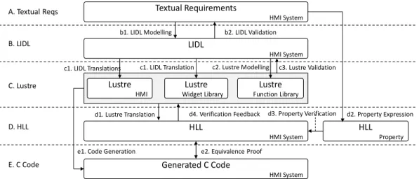
The architecture of the formal development process is depicted in Fig. 1. It translates textual requirements (A) to verified C code (E), through following phases:
• (B) LIDL design phase: (b1) modeling the textual requirements in LIDL, including the data type, interfaces, interactions, and interactive behaviors, etc.; (b2) validating the LIDL model with respect to the textual requirements using the simulator for LIDL models.
• (C) Lustre design phase: (c1) translating the LIDL HMI and widget models into the Lustre models; (c2) modeling function library in Lustre with respect to the LIDL specification; (c3) validating the integrated Lustre model using luciole simulator.
• (D) HLL verification phase: (d1) translating Lustre to HLL using Lustre-to-HLL translator; (d2) expressing properties in HLL with respect to the textual requirements. (d3) verifying properties using S3; (d4) diagnosing errors in case of failure using counterexamples generated by S3.
• (E) Code verification phase: (e1) generating C code using
lus2c code generator; (e2) proving equivalence of the
verified HLL model and the generated C code.
The languages LIDL, Lustre and HLL are involved in the process. The LIDL language is a synchronous language , and its semantics and definition are close to the ones of Lustre and HLL. Therefore, our proposal could be adapted to an industrial development process contered on industry grade technologies such as Esterel’s SCADE that is fundamentally related to Lustre synchronous approach.
A. LIDL Modeling Language and Tools
LIDL allows for the specification of interactive entities named interactors. An interactor is described in LIDL by its interface and its interaction. Interfaces describe control and data flows between interactors. Interactions describe the behavior of the interactor as the transformation performed between input and output flows. In LIDL, flows are synchronous, as in Lustre, for instance. LIDL allows the users to describe, in an abstract way, the interface; in a concrete way, the interactions associated to the interfaces. All details about LIDL can be found in this thesis [6].
B. Lustre Modeling Language and the Toolset
Lustre [14] is a formal, declarative, and synchronous dataflow language for programming reactive systems. It has been used as the core language of the industrial environment SCADE. The Lustre toolset provides various tools, e.g., simulator, code generator, and model checker. Our work relies on the luciole simulator and the lus2c code generator.
C. HLL Modeling Language and the S3 Toolset
HLL, the modeling/verification language of the S3 toolset, is a synchronous dataflow language used to model a system, its environmental constraints as well as its properties. To give an overview of the language constructs, Fig. 2 shows the HLL
LIDL HMI System Lustre HMI Lustre Widget Library HLL HMI System B. LIDL C. Lustre D. HLL
c1. LIDL Translations c1. LIDL Translation
d1. Lustre Translation Textual Requirements HMI System HLL Property d3. Property Verification b2. LIDL Validation d4. Verification Feedback Generated C Code HMI System e1. Code Generation e2. Equivalence Proof
E. C Code b1. LIDL Modelling A. Textual Reqs c2. Lustre Modelling d2. Property Expression Lustre Function Library c3. Lustre Validation
Fig. 1. Architecture of Formal Development Process of HMI
model of a saturated counter (in Counter namespace) and its property on the range of output value (in Counter_Verif
namespace). The counter reacts to the input command (modelled as an HLL enumeration): incrementation (INC),
decrementation (DEC) or reset (RESET). The saturation range is
defined by HLL constants. The behavior of the counter is initialized to zero and then periodically updated. The effect of INC and RESET are directly defined in the schedule, while the effect of DEC is defined as a function contract by using HLL constraints and an intermediate variable dec_input of the HLL
block Fun_dec(). Namespaces: Counter {
Types: enum{INC, DEC, RESET} Command; Inputs: Command in;
Constants: intC_MIN := 0; int C_MAX := 100; Declarations: int unsigned 32 cnt;
Outputs: cnt;
Declarations: int unsigned 32 dec_input;
Blocks: Fun_dec(int pre_v) -> (int v) {v:= dec_input;} Constraints:
ALL f: Fun_dec (f.pre_v = C_MIN > d.v = C_MIN); ALL f: Fun_dec (f.pre_v > C_MIN > d.v = f.pre_v - 1); Definitions:
cnt := 0, if in==RESET then C_MIN elifin==DEC then Fun_dec(cnt) elifin==INC then
if cnt==C_MAX then C_MAX else cnt + 1 else cnt;
}
Counter_Verif { Proof Obligations:
(Counter::cnt >= Counter::C_MIN)&(Counter::cnt <= Counter::C_MAX); }
Fig. 2. An Example of HLL Model
Design models specified in SCADE/Lustre or code in C/Ada can be translated to HLL using the translators of S3. Then, the HLL model is automatically translated to a LLL model (Low Level Language) containing only boolean flows and restricted to three bitwise operators: negation, implication, and equivalence. Finally, the LLL model is provided to the proof engine of S3, S3-core, a SAT-based model checker which implements Bounded Model Checking (BMC) and k-induction [15] techniques.
S3 supports different activities of a software development process: property proof, equivalence proof, automatic test case generation, simulation, and provides necessary elements to comply with the software certification processes. It has been used for the formal verification of railway signaling systems by various industrial companies in this field. More details about HLL and S3 can be found in [16] [17].
IV. THE USE CASE
The design and verification approach presented in this paper has been applied on the Alert Management System (AMS) used by TwIRTee, a small three-wheeled robot studied in the INGEQUIP project to experiment and evaluate methods and tools in the domain of HW/SW co-design [18] and formal verification [16] [17] [19] [20].
The AMS serves the same purpose as a Flight Warning System in an aircraft: it provides a supervision operator (the supervisor) with information about the state of the system, and more specifically about the occurrence of conditions that require immediate corrective actions, or alerts. An alert is said to be active when some specific condition is observed on the monitored system. “Left wheel is blocked” or “Battery is low” are typical examples of alerts. An alert signal is the means by which the supervisor is informed of the occurrence of the alert activation. The presentation of an alert signal to the supervisor shall transmit sufficient information to ensure an appropriate level of situation awareness. This requirement impacts the amount of information presented at once to the supervisor, the duration of the presentation, the order according to which alerts are presented, etc. Alert conditions are computed from data collected from the various parts of the system. A dedicated component, coded in Lustre, computes the activation condition from those data.
ACK CLR PROC Alert 6 Some text #alerts : 20 Alert 10 some text Alert 2 [PROC 1.2]
Alert 7 [PROC completed]
1. Check this Alert 3 some text Alert 1 Some text #acked alerts : 14 TARGET WINDOW
Fig. 3. The Alert Display Panel
Active alerts are ordered according to multiple criteria: criticality of the alert, time of occurrence of the alert, state of the alert, etc. The result is a totally ordered set of alerts. In
practice, active alerts are presented in slots, i.e., a small display area containing a brief description of the alert (see to on Fig. 3). As the room on the display is limited, only part of the alert list, a “window”, can be displayed at once. Therefore, the supervisor is provided with interaction means to navigate in the list of active alerts (see). Note that the last activated alert is always displayed in a dedicated area (see ). Additionally, another set of interaction means (see and ) is provided to change the state of a specific alert — the target alert (see ) — from active to acknowledged or cleared. Acknowledging the alert changes the way it is displayed: a large slot (2 lines, see ) is allocated to a non- acknowledged alert; a small slot (1 line, see ) is allocated to an acknowledged alert. Clearing an alert simply removes the corresponding slot from the slots list. The slot of the target alert is signalled by a dark border.
The target alert and the target slot can be changed independently using dedicated interaction means, however (i) the target alert shall always be displayed on the target slot, and (ii) the displayed slots shall always display alerts in the order in which they appear in the list of active alerts.
Let’s consider that alert and slot s are selected. Then if the user moves the alert selection cursor “up”, the display will basically scroll down so that the alert location − 1 is displayed on slot . Conversely, if the user moves the slot selection cursor “up”, then slot − 1 becomes selected, and it shows alert . In some conditions, the two movements are correlated. Thus, if alert a and topmost slot ( = 0) are selected, then moving the slot selection cursor up will actually move the alert selection cursor down, i.e., alert − 1 is displayed on slot 0.
Even such a simple function raises non trivial verification issues, in particular as alerts can be activated or deactivated at any time. Some properties to be verified are introduced in the part concerning verification.
V. FORMAL ACTIVITIES IN THE DEVELOPMENT PROCESS
This chapter details our contributions about the formal activities in the different phases (B, C, D, and E in Fig. 1) of the development process.
A. From Textual Requirements to LIDL Specification
The structure of AMS interfaces can be abstracted manually from the textual requirements. In particular these requirements refer to types of data that can be abstracted and represented as:
data AlertId is Number data Date is Number data Category is Number data Move is Number data Alert is { Id : AlertId, activated : Boolean, staticPrio : Number, acked : Boolean, timestamp : Date, category : Number, dynamPrio : Number
} data AlertText is Text
The interfaces of the alert management system include the interface with the rover system:
interface System is
{
actAlertId : Number in,
actTimeStamp : Date in,
Alerts : Alert[8] in,
ackedAlertId : Number out
}
This interface receives a permanent flow of Alerts (8 Alerts). These alerts can be activated and the actAlertId flow
gives the number of the activated alert and alertTimeStamp
gives the Date at which the alert was activated. An alert can be acknowledged by the user and in that case this information is returned by using the flow ackAlertid.
Similarly the interface with the user that monitors the rovers can be built in the following way:
interface User is
{
ackAlertId : Number in,
alertMove : Move in,
slotMove : Move in,
slotdisplayed : Boolean[8] out,
alertSlot : AlertText[8] out
}
This interface expresses that the text of alerts are displayed by means of a set of 8 slots. A specific alert (the “selected” alert) is displayed on a specific slot (the “selected”’ slot). As explained in the previous section, the selected alert and the selected slot can be changed using dedicated cursors (alertMove, slotMove) that can be moved up and down.
Finally, the user can also acknowledge the selected alert. The LIDL specification is given by the following interaction definition that depicts how to manage alerts between a rover system and a user by using the two interfaces previously defined. This interaction is the topmost one. The interaction (manage alerts between (roverSystem : System) and (controlUser : User)) realizes concurrently
all the interactions that are involved in its definition. The first
five interactions describe the whole behavior that is embedded in the global interaction. Each of them is also defined in LIDL and is a part of the whole formal specification. The two last ones describe how flows are related to the two interfaces
System and User. It can be seen that the alertSlot definition of
the User interface is associated with a flow that is an AlertText out and that is produced by the interaction text of alert number (alertNumber : AlertId in). This interaction gives the text
that corresponds to an alert id.
interaction (manage alerts between (roverSystem : System) and
(controlUser : User)) : Activation in is (all
(sort alerts (alerts) by priority on activation of
(activatedAlertId) at (activationTime) or acknowledge of (acknowledgedId) giving (SortedAlerts))
((SelectedAlertId) is the alert id of the alert selected by the user when moving by (alertSelectionMove) in (SortedAlerts)) (A move (slotSelMove) on slot selector selects a new slot for alert (SelectedAlertId) in (SortedAlerts) by designating which slot is activated in (SlotsActivated))
(display the selected alert (selectedAlertId) in the selected slot given as activated in (SlotsActivated) and give the alert id of the alert newly inserted in each slot (alertIdSlots))
(display the slots (displayedSlots) with alert texts corresponding to alert identifiers (alertIdSlots))
((roverSystem) = ({actAlertId : (activatedAlertId),
actTimeStamp : (activationTime),
Alerts : (alerts),
ackedAlertId : (acknowledgedId)}))
((controlUser = ({ackAlertId : (acknowledgedId),
alertMove : (alertSelectionMove),
slotMove : (slotSelMove),
slotdisplayed : (displayedSlots)
alertSlot : (text of alert number (alertIdSlots))
)
Clearly, the LIDL syntax allows writing a specification that is (i) very close to natural language, (ii) fairly easy to understand, and (iii) formal. The formal aspect of the language resides in the definition of flows by means of very elementary and basic constructions of the language. The resulting (formal) model of the interactive system shall now be verified before being translated into some executable software. Toward these goals, we first translate the LIDL model into Lustre. In this way, we leverage the existing means provided by the Lustre toolchain.
B. Model Translation from LIDL to Lustre
The LIDL to Lustre translation tool relies on a pre-processing of LIDL specification to inline the interface and data definitions and to keep only interactions. An external static Lustre library provides a translation for each LIDL data type and each LIDL construct2. The translation strategy is then
(i) to type each data flow; (ii) to map each LIDL construct instance to its Lustre translation; and (iii) to provide necessary code and variables to make the mapping between flows linking the native interactions. The implementation of our LIDL to Lustre translator is based on the original work conducted during the design of the language [13]. The overall architecture of the tool has been kept as the original with modifications on the workflow to add the missing translation phases (typing, variables generation).
In this setting, the (Button triggers (triggeredSignal: Activation out)): Button interaction is first inlined by the
translator to replace the Button interface with its definition: click: Activation in. The output of the translator is then:
-- Interaction Buttontriggers$ [1:13|1:91]
node Button_triggers__triggeredSignal_Activation_out(
theInterface_click: Activation)
returns (theArgs_triggeredSignal: Activation) let
-- Native [2:1|2:28]
theArgs_triggeredSignal = assign_Activation(theInterface_click, theInterface_click);
tel
As we can see, the definition of the interaction is translated as a Lustre node. The arguments and interface atomic flows with in direction are used as inputs of the node and the ones with out direction are used as outputs of the node. We note that the Activation LIDL type is translated as the bool Lustre type. As each operator of the language is translated using the Lustre
2 At the time of writing, a few constructs are not yet handled by the translator. The development is ongoing.
library, the assignment (() = ()) operator is translated as a call to the assign_Activation node statically defined as:
node assign_Activation(activation: bool; in: bool) returns (out: bool)
let
out = if (activation) then in else false;
tel
Our translator also provides traceability links between the input LIDL specification constructs location (line and columns) and the output Lustre code (with a comment for each Lustre construct/equation). An example can be found in the generated Lustre code for the Button triggers interaction. Each generated line has an additional traceability comment in a preceding line. The generated code is human-readable but some work is to be done as links between operations is done through variables and equations order to not necessarily reflect the execution order.
After this translation phase, the initial LIDL model is expressed using Lustre code. However, as LIDL is not a programming language, a LIDL model usually refers to some low level interactions directly coded in Lustre and provided as a reusable library. This approach is similar to what is done with SCADE or Simulink where low-level, reusable or performance-critical operators are directly coded in C.
C. Library Design in Lustre: The Slot Management
Three important design choices determine the design of the alert slot management.
First, we chose a synchronous implementation in order to (i) comply with the execution semantics of LIDL and (ii) to facilitate the verification with S3. The design is expressed in Lustre and transcoded in C using the lus2c tool. Furthermore, the state of the alert panel is completely updated in one execution cycle (i.e., the update is not decomposed into a succession of cycles).
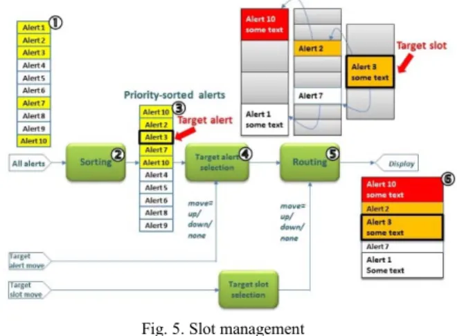
Second, we have chosen a design where the slots are statically defined, allocated, and positioned on the panel. In order to account for all possible ordering of acknowledged (1-line) and non-acknowledged (2-(1-line) slots, we create three sets of slots (see Fig. 4). One set contains the large slots vertically aligned with the panel borders (); the next set contains the small slots vertically aligned with the panel borders (), and the last set contains the large slots vertically offset by the height of a small slot (). Using an appropriate combination of slots from these 3 sets, any list of slots can be displayed. An example is given on the right-hand side of Fig. 4. It is worth noting that this is not the only possible design solution. For instance, another solution could use one single set of slots and could use values of positions and heights to setup the slot panel.
Finally, the slots to be displayed (from the three sets) are selected and their attributes, color and message, are set. Again, this operation is done synchronously by propagating an activation signal from slot to slot, starting from the target slot. The activation signal propagate up and down according to the state of the alerts (acknowledged or not), so as to avoid the situation where slots would overlap. An example is given on
Fig. 4, here, the activation signals are propagated upwards and downwards from the slot allocated to alert 3.
Fig. 4. Slot sets
The functional architecture of the slot management system is depicted in Fig. 5. First, the list of all alerts given in input ( , active alerts are represented in yellow) is sorted according to a total ordering function taking into account the category of the alert (warning, caution, advisory), its time of activation, its acknowledgment state, etc. Sorting is achieved in a synchronous manner using a bitonic sorting network. Then, the target alert is selected according to the state of the “target alert movement” buttons (up/down/no movement). This functional block is implemented in a synchronous manner: the priority of the target alert for the previous cycle is propagated “down the list” to find out the new selected alert.
Fig. 5. Slot management
D. Property Verification and Error Diagnostics using S3
The formal verification in our development process addresses both HMI and system properties. The works [4] [5] identified four categories of HMI properties for the UIs: (1) reachability, (2) visibility, (3) task related property, and (4) reliability. In this part, we first show how these properties are formalized in HLL; then present the verification process using S3 and explain the diagnosis of design errors and missing pre-conditions; at last describe the contract-based verification approach.
1) Formal Property Expression in HLL
Reachability properties make assertions about the ability
of the interface to eventually reach a particular state. The HLL expression of the generic reachability properties is P → SOME s: States Q), where P is a pre-condition and Q is eventually reachable prediction.
Visibility properties assert that visual feedback will
eventually result from an action. An example of AMS requirements (REQ-16) and its HLL expression are given.
REQ-16: Only active alerts shall be displayed. PROP-16:
s: slots s. id ! = −1 → i: 0, 7 a i . id = s. id → a i . act)
Task-related properties describe the human behaviors that
the interface is expected to support. An example of AMS requirements (REQ-8-1) and its HLL expression are given.
REQ-8-1: If the user clicks the [target alert up] button and the priority of
previous selected alert is greater than the priorities of any current alerts, then the target alert shall be at the top of the alert list(*).
PROP-8-1:
aselmov = up & i: 0, 7 p > a i . p ) → idx = 0 (*) Index of the returned alert shall be 0.
Reliability properties describe desirable interface
properties that support safe HMI. An example of AMS requirements (REQ-17) and its HLL expression are given.
REQ-17:The target alert shall always be displayed in the target slot.
PROP-17:
ALL s: Slots, a: Alerts s. x = target &s. y = target &a. idx = target → s. id = a. id)
2) Property Verification Process using S3
Fig. 6 presents the process of property verification using S3. This process starts from the Lustre model, which integrates the Lustre model translated from the LIDL model and those from the Lustre functional library. This Lustre model is translated to HLL, combined with HLL properties, and then expanded to LLL to be solved by S3-core. If a property is falsifiable, generated counterexamples can be simulated at HLL or Lustre level. The simulation activity helps diagnose the Lustre design model, the translated HLL model and the HLL property.
Fig. 6. Property Verification Process using S3
Usually, properties are classified as safety or liveness ones. The former declares what should not happen (or should always happen), while the latter declares what should eventually happen. The completeness of a safety property can be achieved with k-inductive proof based on strengthening inductive invariants (also referred to as lemmas). S3 provides automatic analysis tools to help the search of lemmas. In the safety-critical embedded systems, the reachability properties are usually restricted to a bounded time, which allows us to handle the liveness property as the reachability one using the “lasso” approach [21].
3) Diagnosis of Design Errors
The error diagnosis is illustrated using an example from the function (alertssel) of target alert selection in AMS. We give the lustre model of this function in Fig. 7, where aselmov is the human input event, p is the priority of an alert, idx is the index of alert in the alert list. This function depends on another function alertsel.
functionalertssel ( aselmov : Move; a : Alert^8; p : int)
returns( idx : int);
var
p0, p1, p2, p3, p4, p5, p6, p7 : bool;
idx0, idx1, idx2, idx3, idx4, idx5, idx6 : int;
let
p0, idx0 = alertsel( 0, aselmov, a[0], true, p, -1) ; p1, idx1 = alertsel( 1, aselmov, a[1], p0, p, idx0 ) ; …
p7, idx = alertsel( 7, aselmov, a[7], p6, p, idx6 );
tel
Fig. 7. Lustre Model of the Function of Target Alert Selection
We take an AMS requirement (REQ-8-1)as example
(previously defined in Sect. V.D.1) to explain the diagnosis. This property does not hold. A counterexample is generated, shown hereafter, where the index of the returned alert (idx) is
-1 (should be 0 according to the requirement). This counterexample scenario is simulated in both HLL and Lustre models. The error in the design (see Fig. 7) is found: the value of the last parameter in the first invocation of the function
alertsel should not be -1.
idx = −1
aselmov = up
p = 6132
a.p = [6006, 6005, 6004, 4089, 4025, 3967, 3960, 3579, 3318]
4) Diagnosis of Missing Constraints
Sometimes the violation of properties are due to the misunderstanding about some constraints of the function or the system. Consider the following AMS requirement.
REQ For any couple of different alerts (a1, a2) such that 1. ≠ 2. , their
global priorities (gp1, gp2) shall be different.
PROP: Constraints: a1.id ≠ a2.id ;
Proof Obligations: a1.gp ≠ a2.gp;
The counterexample of this property is shown hereafter, where two alerts (a1 and a2) with different ids (a1.id = 5 and a2.id = 2) have same global priorities (p = 8). This
counter-example is caused by the fact that a1 and a2 are given identical timestamps (ts = 0), which should be explicitly forbidden by
using a constraint (a1.ts ≠ a2.ts ).
a1 = {id: 5, act: t, p: 8, acked: t, ts: 0, cat: warning} a2 = {id: 2, act: t, p: 8, acked: t, ts: 0, cat: warning} gp1= 851968
gp2= 851968
5) Contract-based Verification
Design by Contract is widely applied to improve the reliability of software systems. A contract varies from a simple assertion such as the assertion macros in C and C++ to domain-specific contract languages. Contract-based verification [22] [23] allows reasoning on component-based design using contracts, which makes the verification of complex hierarchically defined system more scalable.
We experimented contract-based verification on a set of AMS properties to evaluate its efficiency. To explain the principle of contract, an example (REQ-8-1) is given. The
pre-condition of this property is that the list of alerts (a[8]) has been sorted, expressed as the HLL constraint.
REQ-16: Only active alerts shall be displayed.
Constraints: ALL i : 0,7 , j : 0,7 i < j → a i . gp > a j . gp) ;
3 We do not consider the verification of properties related to the software/hardware integration which (currently) rely on testing.
TABLE 1 provides the statistics of the verification time for a set of properties, with or without contracts. The experimental results show that the scalability of formal verification has been significantly improved for some properties.
TABLE 1.STATISTICS OF CONTRACT-BASED VERIFICATION
Property Without contract With contract REQ-13 2 sec 1 sec REQ-14 152 min 1 sec REQ-15 32 min 1 sec REQ-16 98 min 1 sec REQ-18-1 5 min 40 sec
E. Code Verification using S3
At this stage of the process, properties are verified on the Lustre model. The C code, either manually implemented or automatically generated from Lustre, needs to be formally verified to ensure that it conforms to the initial requirements, before being embedded in the execution platform3. This
demonstration can be achieved in three different ways: • Properties are verified on the Lustre model and the
preservation of these properties in the code is ensured by the qualified code generation tool. In that case, most verification activities at code level can be alleviated, but the code generator must be qualified, which may be costly. • Properties are verified in the final code. However, applying
some formal verification techniques at the code level can be very difficult due to the lacking of abstraction.
• Properties are verified on the Lustre model and an equivalence proof is conducted to ensure that the design model and the final code are equivalent.
The code generator in our work is not qualified, and the cost of verifications on the final code is relatively high. According to the above analysis, the last solution is thus adopted.
Proving the equivalence of two models (or one program and one model) requires that their pertinent observable behaviors are identical for any valid sequence of inputs. Our approach guarantees the correctness of the AMS code by proving equivalence between the HLL model and the generated C code. Fig. 8 presents the process of equivalence proof. On the one hand, the Lustre model is translated to an HLL model using Scade-translator. On the other hand, the C code (generated from the Lustre model by using lus2c generator) is translated into another HLL model using C-translator. Both HLL models are then expanded to LLL models using diversified expanders. The equivalence model is constructed and proved using S3-core.
Lustre Model translate
C Code HLL Model Lustre HLL Model C Code LLL Model Lustre LLL Model C Code generate translate expand expand equivalence proof using S3
VI. CONCLUSIONS AND PERSPECTIVES
This paper proposes a formal verification process covering a significant part of the development process of a safety-critical HMI, from textual specifications to the final code. This process is supported by a set of formal languages (LIDL, Lustre, and HLL) and their relevant tools, including a specifically developed LIDL-to-Lustre translator and the S3 formal verification toolset. It has been applied to the development of the display component of an Alert Management System of a small robot. Additionally, a contract-based verification technique to reduce the overall verification effort has been applied and evaluated. Experimental results show that the formal methods are indeed suitable for the development of safety-critical HMI software.
Concerning the LIDL language, work is currently on-going in the framework of the FORMEDICIS project to complete and improve the language, including the provision of additional constructs to facilitate modeling, and means to express properties. The LIDL to Lustre tool should also be improved in terms of maturity and features, and the correctness of this translation should be addressed. On the verification side, results of property verification using S3 should be expressed at the level of the input model (expressed in LIDL) rather than at the HLL level. This high-level feedback would leverage the bidirectional traceability links generated by the LIDL to C translator.
Another direction would be to skip the translation to Lustre for verification purposes. A possibility would be to translate LIDL design models directly to some verification language, such as HLL or SMT-Lib. Verification would be done using SAT/SMT solvers. Other verification techniques such as symbolic model checking or static analysis are expected to be integrated in the LIDL verification framework. In case of using SMT solvers, a qualified code generator from SMT-Lib to embedded code is needed. Another direction is to use the Event-B [24] correct by construction method. Once the final refinement of design is obtained, the verification of generated code is handled by tools such as the ones advocated in [19].
ACKNOWLEDGMENTS
This work has been funded by the INGEQUIP project. The authors would like to thank the members of the project for their cooperation.
REFERENCES
[1] B. A. Myers, “Why are Human-Computer Interfaces Difficult to Design and Implement,” Jul. 1993.
[2] J. Reason, Human Error. Cambridge University Press, 1990.
[3] B. Shneiderman, C. Plaisant, M. Cohen, and S. Jacobs, “Designing the User Interface: Strategies for Effective Human-Computer Interaction,” CEC Faculty Books and Book Chapters, Feb. 2009. [4] J. C. Campos and M. D. Harrison, “Formally Verifying Interactive
Systems: A Review,” in Design, Specification and Verification of
Interactive Systems ’97, Springer Vienna, 1997, pp. 109–124.
[5] M. L. Bolton, E. J. Bass, and R. I. Siminiceanu, “Using Formal Verification to Evaluate Human-Automation Interaction: A Review,”
IEEE Transactions on Systems, Man, and Cybernetics: Systems, vol.
43, no. 3, pp. 488–503, May 2013.
[6] V. Lecrubier, “Un langage formel pour la conception, la spécification et la vérification d’interfaces homme-machine embarquées critiques,” l’Institut Supérieur de l’Aéronautique et de l’Espace (ISAE), https://tel.archives-ouvertes.fr/tel-01455466, 2017.
[7] J. C. Campos and M. D. Harrison, “Interaction Engineering Using the IVY Tool,” in Proceedings of the 1st ACM SIGCHI Symposium on
Engineering Interactive Computing Systems, New York, NY, USA,
2009, pp. 35–44.
[8] S. Combéfis, D. Giannakopoulou, C. Pecheur, and M. Feary, “A formal framework for design and analysis of human-machine interaction,” in 2011 IEEE International Conference on Systems,
Man, and Cybernetics (SMC), 2011, pp. 1801–1808.
[9] K. Havelund and T. Pressburger, “Model checking JAVA programs using JAVA PathFinder,” STTT, vol. 2, no. 4, pp. 366–381, Mar. 2000.
[10] D. Navarre, P. Palanque, J.-F. Ladry, and E. Barboni, “ICOs: A Model-based User Interface Description Technique Dedicated to Interactive Systems Addressing Usability, Reliability and Scalability,” ACM Trans. Comput.-Hum. Interact., vol. 16, no. 4, p. 18:1–18:56, Nov. 2009.
[11] R. Oliveira, S. Dupuy-Chessa, G. Calvary, and D. Dadolle, “Using Formal Models to Cross Check an Implementation,” in Proceedings
of the 8th ACM SIGCHI Symposium on Engineering Interactive Computing Systems, New York, NY, USA, 2016, pp. 126–137.
[12] S. Chatty, M. Magnaudet, and D. Prun, “Verification of Properties of Interactive Components from Their Executable Code,” in
Proceedings of the 7th ACM SIGCHI Symposium on Engineering Interactive Computing Systems, New York, NY, USA, 2015, pp.
276–285.
[13] P. A. Abdulla, J. Deneux, G. Stålmarck, H. Ågren, and O. Åkerlund, “Designing Safe, Reliable Systems Using Scade,” in Leveraging
Applications of Formal Methods, Springer Berlin Heidelberg, 2004,
pp. 115–129.
[14] N. Halbwachs, P. Caspi, P. Raymond, and D. Pilaud, “The synchronous data flow programming language LUSTRE,”
Proceedings of the IEEE, vol. 79, no. 9, pp. 1305–1320, Sep. 1991.
[15] M. Sheeran, S. Singh, and G. Stålmarck, “Checking Safety Properties Using Induction and a SAT-Solver,” in Formal Methods in
Computer-Aided Design, W. A. H. Jr and S. D. Johnson, Eds.
Springer Berlin Heidelberg, 2000, pp. 127–144.
[16] M. Clabaut, N. Ge, N. Breton, E. Jenn, R. Delmas, and Y. Fonteneau, “Industrial Grade Model Checking Use Cases, Constraints, Tools and Applications,” in 8th European Congress on Embedded Real Time
Software and Systems (ERTS 2016), Toulouse, France, 2016.
[17] N. Ge, E. Jenn, N. Breton, and Y. Fonteneau, “Formal Verification of a Rover Anti-collision System,” in Critical Systems: Formal
Methods and Automated Verification, Springer International
Publishing, 2016, pp. 171–188.
[18] P. Cuenot, E. Jenn, E. Faure, N. Broueilh, and E. Rouland, “An Experiment on Exploiting Virtual Platforms for the Development of Embedded Equipments,” in 8th European Congress on Embedded
Real Time Software and Systems (ERTS 2016), 2016.
[19] N. Ge, A. Dieumegard, E. Jenn, and L. Voisin, “Correct-by-Construction Specification to Verified Code,” 2017.
[20] A. Dieumegard, N. Ge, and E. Jenn, “Event-B at Work: some Lessons Learnt from an Application to a Robot Anti-Collision Function,” in
NASA Formal Methods Symposium, 2017, pp. 327–341.
[21] A. Biere, C. Artho, and V. Schuppan, “Liveness Checking as Safety Checking,” Electronic Notes in Theoretical Computer Science, vol. 66, no. 2, pp. 160–177, décembre 2002.
[22] P. Boström, “Contract-Based Verification of Simulink Models,” in
Formal Methods and Software Engineering, Springer Berlin
Heidelberg, 2011, pp. 291–306.
[23] M. Dahlweid, M. Moskal, T. Santen, S. Tobies, and W. Schulte, “VCC: Contract-based modular verification of concurrent C,” in
Software Engineering-Companion Volume, 2009. ICSE-Companion 2009. 31st International Conference on, 2009, pp. 429–430.
[24] Y. Ait-Ameur and M. Baron, “Formal and experimental validation approaches in HCI systems design based on a shared event B model,”
Int J Softw Tools Technol Transfer, vol. 8, no. 6, pp. 547–563, Nov.