Publisher’s version / Version de l'éditeur:
Vous avez des questions? Nous pouvons vous aider. Pour communiquer directement avec un auteur, consultez la première page de la revue dans laquelle son article a été publié afin de trouver ses coordonnées. Si vous n’arrivez pas à les repérer, communiquez avec nous à PublicationsArchive-ArchivesPublications@nrc-cnrc.gc.ca.
Questions? Contact the NRC Publications Archive team at
PublicationsArchive-ArchivesPublications@nrc-cnrc.gc.ca. If you wish to email the authors directly, please see the first page of the publication for their contact information.
https://publications-cnrc.canada.ca/fra/droits
L’accès à ce site Web et l’utilisation de son contenu sont assujettis aux conditions présentées dans le site LISEZ CES CONDITIONS ATTENTIVEMENT AVANT D’UTILISER CE SITE WEB.
Paper (National Research Council of Canada. Division of Building Research); no.
DBR-P-924, 1980-02
READ THESE TERMS AND CONDITIONS CAREFULLY BEFORE USING THIS WEBSITE. https://nrc-publications.canada.ca/eng/copyright
NRC Publications Archive Record / Notice des Archives des publications du CNRC :
https://nrc-publications.canada.ca/eng/view/object/?id=bb3db704-e29a-4392-94aa-e77fb84a9a8a https://publications-cnrc.canada.ca/fra/voir/objet/?id=bb3db704-e29a-4392-94aa-e77fb84a9a8a
NRC Publications Archive
Archives des publications du CNRC
This publication could be one of several versions: author’s original, accepted manuscript or the publisher’s version. / La version de cette publication peut être l’une des suivantes : la version prépublication de l’auteur, la version acceptée du manuscrit ou la version de l’éditeur.
For the publisher’s version, please access the DOI link below./ Pour consulter la version de l’éditeur, utilisez le lien DOI ci-dessous.
https://doi.org/10.4224/40001774
Access and use of this website and the material on it are subject to the Terms and Conditions set forth at
Penetration of fire partitions by plastic pipe
no, 924 cop. 2
B L U d . CONSEIL NATIONAL DE RECHERCHES DU CANADA NATIONAL RESEARCH COUNCIL OF CANADA
Penetration of Fire Partitions
by
Plastic Pipe
by P. C. Attwood
Reprinted from FIRE TECHNOLOGY Vol. 16, No. 1, February 1980
p. 37-62
DBR Paper No. 924 Division of Building Research
Comme le langage transmet l'idke de la gravitk d'un incendie par une unique expression, il a toujours semblk souhaitable de trouver un seul paramktre pour la chiffrer. La suggestion prkckdente de l'auteur voulant que I'adsorption totale de chaleur par l'unitk de surface des limites des compartiments au cours de la pkriode de pleine activitk d'un incendie, nommke l'indice de gravitk d'un in- cendie, utiliske comme mesure du potentiel de destruction des in- cendies, a subi un examen critique. I1 se trouve que l'indice est en fait un descripteur raisonnablement reprksentatif de la gravitk des incendies de compartiments, quels que soient leurs anttckdents thermiques.
REPRINTED FROM
FIRE TECHNOLOGY
Penetration o f Fire Partitions
by
Plastic Pipe
P. C. ATTWOOD
Division of Building Research National Research Council of Canada
Plastic DWV pipe will not propagate flame through a fire separation even under adverse pressure differentials if appropriate barrier devices and construction methods are used. This paper reports the results of a small-scale test program that studied the penetration of fire separations by plastic drain, waste, and vent pipe.
T
HE PRIMARY concern expressed when considering the use of plastic pipe in high-rise buildings lies in the opinion that the plastic will bum and thus directly propagate fire beyond a fire separation or open a path for transmission of hot gases from the fire compartment. This paper presents the results of a test program designed to study the behavior of plastic pipe and to determine what circumstances would permit the use of plastic pipe without jeopardizing the integrity of fire partitions.McGuirel has reported a series of small-scale tests primarily dealing with horizontal pipes penetrating vertical fire separations. In that report, work by Tamura2 was cited as justification for conducting tests a t a positive pressure of about 0.2 in. (5 rnm) water gage (WG). Tamura showed that, under winter conditions, pressure differentials of this level could exist across exterior w d s in high-rise buildings. In the event of fire, broken win- dows would allow a similar pressure differential across an interior fire separation because the compartment pressure would equalize with the ex- terior pressure. A premise adopted for this program was that all tests would be conducted a t a positive pressure of approximately 0.2 in. (5 mm) WG to be representative of pressures that might exist in a fire.
T E S T F A C I L I T I E S
Horizontal and vertical penetrations were treated independently in this study, and thus two small-scale furnaces were utilized. For horizontal pipe
NOTE: Mr. Attwood is a Fellow of the Society of the Plastics Industry of Canada.
37
Copyright 0 1 980, NATIONAL FIRE PROTECTION ASSOCIATION
38 Fire Technology
assemblies, a two-chambered natural gas-fired furnace was used (Figure 1).
For vertical pipe assemblies, a singlechamber box furnace was used, with
propane as the fuel (Figure 2).
B U R N E R ( 8 )
I I C Y L I N D E R 1 I
I I I
B R I C K O U T E R SHELL.
Figure I. Vertical section of furnace.
4 - I N . C O N C R E T E S L A B W I T H O P E N I N G S F O R P I P E A S S E M B L I E S I F L U E D A M P E R C A C C C (I\
Figure 2. Vertical plumbing assemblies test furnace.
The doublechambered furnace for horizontal assemblies was heated by eight burners located in the outer shell. The products of combustion passed into the inner chamber where the test assembly was exposed. The test assembly was mounted in one end of the inner chamber, while the other end
Plastic Pipe 39
of the chamber was covered by an asbestos sheet. A viewing port was pro- vided in the covered end to allow observation of the interior of the furnace.
The box furnace for vertical assemblies was heated by four burners -
one in each side - placed towards the corners. The test assembly was not in
direct contact with the flame from the burners. The top of the furnace con- sisted of a 4-in. (102-mm) thick reinforced concrete slab. The slab was pro- tected by a ceramic insulating material to prolong its life. Two holes were cut in the slab to permit the passage of vertical pipes.
Both furnaces had the flue located in the bottom and used a damper on the exhaust to control the pressure. The use of a forced-air supply ensured sufficient pressure. Each burner could be shut off separately to facilitate temperature control in accordance with the ASTM E-119 timetemperature curve.
In this program failure was defined as any condition that allowed flame or hot furnace gases to escape because of the plumbing assembly.
All tests in this study used either ABS or PVC drain, waste, and vent pipe and were run to a maximum of 2 hours.
H O R I Z O N T A L P I P E A S S E M B L I E S
The first segment of this program studied horizontal plumbing assemblies penetrating vertical fire separations. In these assemblies, a wall section 23 in. by 18 in. (58 cm by 46 cm) was mounted in the open end of the furnace. The plumbing lateral penetrated this wall section and extended into the furnace; generally, this lateral was simply capped on the exposed end, representing the sealing effect of a water-filled trap.
The wall section mounted,in the end of the furnace was constructed in various ways ranging from something as simple as two sheets of %-in.
(16-mm) Type X gypsum board backed by a metal sheet to a section of a
2-hour wall. The simpler forms were largely used during developmental tests.
This section of the program can be broken down into three basic test categories:
Tests where laterals were essentially unprotected; Tests where laterals were sleeved; and
Tests where a mechanical shutoff was created.
Table 1 presents a summary of the significant tests in this horizontal
assembly program.
UNPROTECTED LATERALS
Two tests were run to determine a base point for comparison. Both tests, one in ABS and the other in PVC, utilized similar designs. The plumbing assembly consisted of a 2-in. (50-mm) lateral with a water-filled P-trap on the exposed side. The unexposed side consisted of a 2-in. (50-mm) stack and a sanitary tee for the ABS tests. The PVC test used a double sanitary tee with a lateral extending out the unexposed side. The wall assembly con-
l , , t l l r I . , Y I C ~ ~ I I , n ~ . a ~ r r ~ r t n c V - ~ S I I I I rqm F n p ~ t a r ~ r m s ---
M a n v ~ s l t n n . ? r u r t % ~ r n llqll*llnm c m r n t ~
-- -
I. Impm,*<t4,l 1 a , r n l .
l a 1 2 - 1 " . A85 l i o r > i o n r a l l a r c r r l u r t h ~ l - t ~ , , ~ , , " t o r r n r ~ . t r y te e * n d \ t r r k . I" ~ e n e c r a c l o n burned through. Ieadnng t o l g n l t ~ o n o f S i 8 ~ 1 n type X pyp\um w a l l b o a r d on ? - c n r h ~ l n s t u d . w 8 C h P L P ~ and r l u d r ~n cavity
I 2 . 8 , I I l n r l l a n t ~ l 1a11.1.111 -119 I*-lrm, l n l n fnub?n .ul,..ry f a a 1 * m I I I m s n P l p e and r t u d r lgnlrod n c h l n c a u l r y a f t e r r t r c l . 5 i R - l " r y p e X yrp,um "r,,bo.ird on 2 ~ 1 " I ,,->n \r,,d\ p e n e l r a t ~ o n war expored.
r r t h 2 l ~ g a y e metal backing. Capped l a r c r i l from unexpoqcd i l d e lnro t e e
I . Sleeved larsrals - 4 5 . r n g l c
(a1 I > - , " PVC l s O d o m r r r d l r r e r a l r , t h 5.1" lone l R ~ g a g e r r e c l i i e e ~ c 1111 mln ~ a i l u r e r t 70 m l n Test war ~ n r e n d e d t o ~ n d ~ r a r c
i n t o rye and ,tack. r c p r r a r l o n ronsrrucrlon - : ihcctr length of sleeve rhar would be r e q u ~ r c d for 2 - h r
s / n ~ l n . type 1 gyprum v i l l h v r r d w r t n ~ ~ - p r g e r t c c l b . r k l n y d u r n t ~ o n .
I I .A 4 5 ' dovnurrd laterrl v r r h 1 0 l o n g ~ ~1 8 - g a p e ~ ireel rlecvc :n n l n P ~ p e tarally r o n w m d l e a v ~ n g open path fol I n f o uye and r r a c k . capped on exporcd e n d . w a l l conrtruriron i v r n a ~ e g a s e s .
2 s h e e t . i / B . l " , tme \ eyprvm wallboard
.
16-grgc r t c e ,r h e e l * 2 - 8 " 4 - 1 " rrudr * 1 1 8 - l n type " gypsum wallboard.
I 1 v 4 5 ' domward l a r e r a l n r h 1 3 ~ 1 ~ long ??-gage < t e e , r l c c v c 120 m l n ~ r h plug formed haltwar d o m rlecue. Paper
I n f o xye and s t a c k , " a l l con5rr"crlan 2 \ h e e f r i i 8 . 1 " r f l e X charred on g).pou. wallboard lnslde c a u r t y .
%YP5u..allhuard
.
2.1" " I - I n r t u d r * I sheerr i , R ~ l "lme X gmoum r a l l b o a r d . f l r e r t o n t o n and bocrom o f c r u ~ r v .
( d l 3 - 1 " . PYC li' downward I a r e r a l w ~ r h I l i ~ ~ ~ . 2 1 - p g e r r e r l ileeue. w a l l 120 mln A r h p l u g formed at unerpored end of rleeve
a i ~n l c l , l a i e i a l lnro r y e and I L L " PVC stack ore charrrng ~ n i ~ d e w a l l c a u ~ t y rhan r ~ r h
I ' 1 . l " . PYC.
(el 1 4 - 3 " . PVC 4 i D upward p e n e r r a i l o n ",rh 5 . ~ ~ . l o n g I8.gape sreel \ l e ~ u c . 125 m r n Non-vented iltuaclon preuenlr f l o r of hot
w a l l r o n s t r u r t ~ o n 2 rheerr SIR-ln t y p e X gyp3um urllboard + f u r n a c e g a l e s . L l f t l e d a w g e t o p l p e In i l * F v e .
16-gage r t c e l s h e e t b a r k ~ n g Lxpo-ed inde canrlscr o f rye uacer ~n crap reached I 0 S 0 i .
x i r h s h o r t capped verrlcal r e r r ~ o n 5 . u n s r p o s e d i l d e c o n s l i t s
O f l a t e r a l w i t h u r r e r - i l l l e d P - t r a p .
I, * r h m , r a l .h"l..lf d e v > c e l
l a 1 2 - l n ABS s t e e l , l e e u e " ~ r h i - l n I n l u ~ n t l o n . rerghted flopper r e q c ~ n g 30 ~ e a k a g e r e s u l t e d ,n furnace garer e r c a p l n g ro
0" P'Pe ""expored i l d e ,
( b l 2 ~ 1 " . FVC A S I" i a j :* ma,, prh p r e v e n t e d rlapper frol c o n p l t t e l ~ c ~ o s l n g l c l 1 ' 3 - l n , PYC 4 ~ 1 n l o n g sleeve x r i h gulllotlne mounted on ironc end. l l S -311 Temporary real caused by bllrtered metal
s u r f a c e r . ( d l I ' l r l n . ABS nouhle f l a p p e r a r r e m h l y . I - x n l o n g s l e e v e , ' > - I " f ~ b e r f r r r 120 m l n Insulation ($1 Lk-1" *BS . 41 I n I d ) . ,ill l n l " I f > I $ - l n PYC i 1 0 ( d l 1 2 0 mln ,*I 3 5 1 " . 1 B S &r ~n ( d l I 2 0 mln !hl 3 - 1 " PbC h5 ~n I d ? . 120 min
( 1 1 1 . n . R'I I . tn ' d l , mt .Irh I%" c n . ~ l . r ~ ~ n ,n x8rrrr 120 m r n IIl > % - I n . PVC A 3 3 " ( L ) , 2 . 1 " % r a c k 120 m l n
1 I 5 as ~n ( 1 1 . 2 ~ ~ " . * t a c k . 120 m l n
sisted of %-in. (16-mm) Type X gypsum board on each side of 2-in. by 6-in. (50-mm by 150-mm) pine studs. The exposed gypsum was backed by a sheet of 24-gage sheet metal in the same manner as that used in the program at
the University of California in B e r k e l e ~ . ~ The fit of the pipe at the gypsum
penetration was tight, with a cement seal around the perimeter. The PVC wall section was firestopped a t the top.
In these tests, as in all tests, the ABS and PVC laterals inside the fur- nace sagged and collapsed within 7 min; the pipe burned through in 10 min
Plastic Pipe 41
for ABS and 19 min for PVC, completely exposing the penetration and ig- niting the pipe and studs within the simulated cavity.
SLEEVED LATERALS
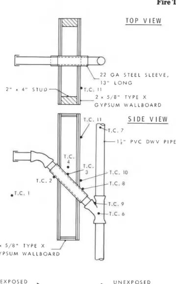
McGuire's paper' demonstrated that horizontal sleeved plastic pipe failed to provide adequate protection; however, exploratory tests showed that sleeved laterals that penetrate walls downward a t an angle of 45" form an effective barrier when PVC pipe is used. With PVC, the intumescent nature of the material combined with the formation of a carboniferous char to retard degradation of the pipe sufficiently that the penetration remained integral for the two-hour test period with both 1%-in. (38-mm) and 3-in. (75-mm) pipe. The wall construction in these two tests was two sheets of %-in. (16-mm) Type X gypsum board on each side of 2-in. by 4-in. (50-mm by 100-mm) studs. The wall cavity was firestopped a t the top and bottom. Figure 3 shows the construction. Figures 4 and 5 graphically present the recorded temperatures from these tests.
A comparison of the graphs suggests that 3-in. (75-mm) pipe is the max- imum diameter that results in formation of a plug in the sleeve. Comparison of the contents of the sleeves after the tests revealed that with 1%-in. (38-mm) pipe the plug had formed approximately halfway down the sleeve, and the pipe below that plug was relatively unaffected. With 3-in. (75-mm) pipe, however, a plug formed a t the unexposed end of the sleeve. The rest of the pipe in the sleeve had been consumed.
A similar test with ABS failed after 26 min. This was due to the fact that ABS is not intumescent and does not burn to an ash as does PVC.
A test using 1%-in. (38-mm) PVC and a 5-in. (127-mm) sleeve was con- ducted to determine the sleeve length dependence of the mechanism. The sleeve was centered a t a simple wall consisting of two sheets of %-in. (16-mm) gypsum board and sheet metal backing. Hot gases and flame escaped through the sleeve after 70 rnin.
A similar wall and sleeve assembly was used to determine whether fire could spread in the reverse direction. The exposed side now consisted of a wye with short vertical sections capped, and the unexposed side consisted of a lateral with a water-filled P-trap. All pipe was 1%-in. (38-mm) PVC. In this case the pipe penetrated the wall upwards a t a angle of 45
"
.
This would represent the situation whereby fire might spread from a vertical service area into a compartment. The key feature was that the unexposed portion of the assembly was a nonvented system. After 125 min the test was ter- minated, a t which time the pipe on the unexposed side of the wall was unaf- fected. The temperature of the water in the trap reached 185" F (85" C). LATERALS WITH MECHANICAL SHUTOFFSThe use of fire dampers is commonplace in heating, ventilation, and air conditioning ducting as a means of preventing smoke and gaseous products of combustion from circulating through a building. The same principle was applied to plastic pipe in this series of tests. Both single and double closures
Fire Technology T O P V l E W
C
2 2 G A S T E E L S L E E V 1 3 " L O N G 2 " x 4 " S T U D - . . m ~ . ~ . I1 2 x 5 1 8 " T Y P E X G Y P S U M W A L L B O A R D S I D E V l E W 1;" P V C D W V P I 5 / 8 " TYPE X G Y P S U M W A L L B O A R Dld
E X P O S E D S I D E+
U N E X P O S E D f-- S I D EFigure 3. Test A 4 - 1 %-in PVCpenetration of fire waU at 45' angle.
were studied and are summarized in Table 1. These devices were adapted from those patented by Wise et al.4
All such devices relied on the softening behavior of plastic pipe at elevated temperatures. The closure device would shut as the plastic col- lapsed, creating a seal.
A variety of single shutoff devices were tested, with failure times generally being around 30 min. Failure was generally caused by poor metal- to-metal seals to PVC ash preventing the devices from shutting. One test did not fail until 115 min. The assembly in this test consisted of a weighted guillotine mounted on the front of a sleeve. Inspection of the assembly after the test revealed that the metal parts had been badly blistered, presumably
Plastic Pipe
I
I
I
I
I
I
I
I
I - / o ' O - o FURNACE TEMPERATURE - T.C. 3 - SLEEVE-INSIDE WALL C A V I T Y T. C. 8 - SLEEVE-UNEXPOSED S I D E - w A I R S P A C E - I N S I D E W Y E - a T.C. 10 - UNEXPOSED SURFACE OFWALL 4" ABOVE SLEEVE
- T.C. 4 - A I R SPACE I N S I D E WALL -. C A V I T Y - 5" ABOVE SLEEVE -- - -
*'
!
I
I
I
I
I
I
I
I
I
I
I
T I M E , m i nFigure 4. Test A# - I %-in PVCpenetration of fire wall a t 45' angle.
as a result of attack by acidic products of combustion of PVC. The blister- ing created a seal a t all metal interfaces.
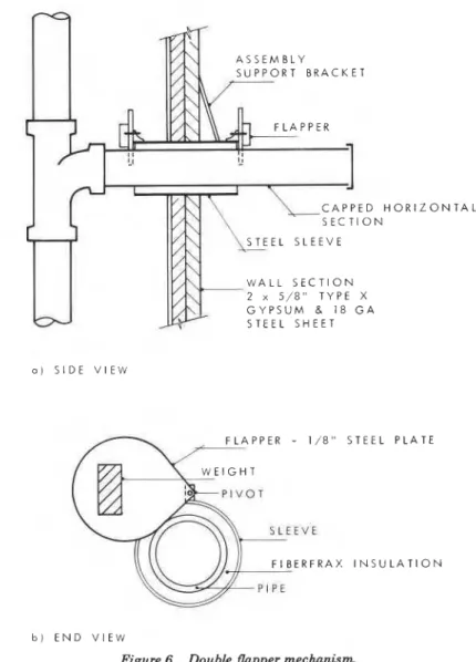
The double shutoff device is shown in Figure 6. I t consisted of a 4411.
(102-mm) long steel sleeve with a swivel flapper mounted a t each end. In all, eight tests were run using this design, with each test running two hours. The mechanism of operation was simply as follows: (a) as the pipe in the fur- nace softened, the exposed end flapper closed, creating a barrier between the furnace and the remaining plumbing assembly; (b) heat conduction and some radiation from the closed flapper slowly caused the pipe within the sleeve to soften and disintegrate; (c) as the softening of the pipe extended to the end of the sleeve, the unexposed flapper closed. This sequence generally took 60 to 70 min. In five of the eight tests, the pipe within the sleeve was
44 Fire Technology T l l l l l l l l
I
d
- - -y o
0 FURNACE TEMPERATURE -SLEEVE - INS I DE WALL C A V I T Y
/"
0 A I R SPACE I N VJALL CAVITY- 5" ABOVE SLEEVE
SLEEVE - UNEXPOSED S l DE d
4 UNEXPOSED SURFACE OF WALL
- 4" ABOVE SLEEVE A I R SPACE INSIDEWYE
I
'
- I * - - 1'-
-. ---
I I A ' 4 ' 1 1 1 1 1 1 1 1 1 1 1 1 T I M E , m i nFigure 5. Test A 4 - 3-in. PVC penetration of fire wall a t 45' angle.
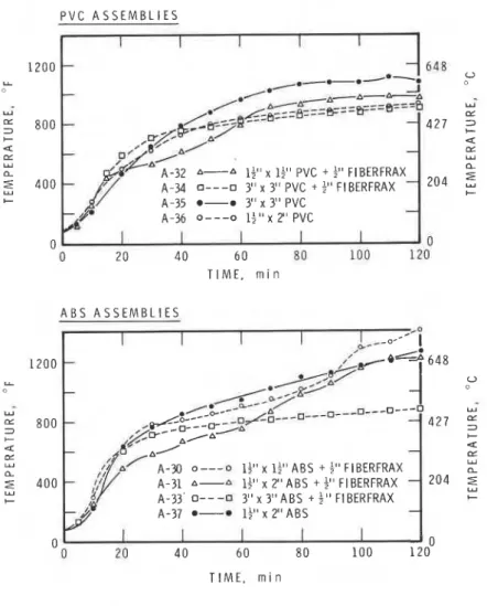
wrapped with %-in. (13-mm) Fiberfrax* insulation. Figures 7(a), (b), and (c) show the recorded temperatures for the air space inside the tee, the sleeve on the unexposed side of the wall, and the temperature on the exterior of the tee respectively. The initial rise in temperatures is due to the venting of fur- nace gases through the plumbing system as the first flapper closes. This causes some deformation in the vertical stack due to the thermal coefficient of expansion. When both flappers had closed, eliminating the source of heat, the stack contracted in such a manner that the remaining pipe withdrew from contact with the shutoff device.
The graphs in Figure 7 reflect this mechanism and also reflect the dif-
*
"Fiberfrax" is a registered trade name for a ceramic fiber material produced by the Car- borundum Company.Plastic Pipe 45 ferences in behavior between ABS and PVC. The initial peaks in Figure 7(a) correspond to the initial passage of furnace gases as the exposed flapper closed. Products of decomposition of the ABS pipe within the sleeve vented through the plumbing system until the unexposed flapper pinched off the pipe. At this time the temperatures dropped and stabilized. With PVC, it is probable that the intumescent nature of the material caused the pipe to plug inside the sleeve. This would force the products of combustion to vent back into the furnace around the exposed flapper. Flame was visible at the flap- per during this period of the tests. Such behavior accounts for the lower and shorter temperature peaks shown in Figure 7(a) for PVC assemblies. I t is evident that the presence of insulation inside the sleeve had no significant effect. A S S E M B L Y S U P P O R T B R A C K E T a ) S I D E V l E W F L A P P E R - 1 / 8 " S T E E L P L A T E W E I G H T 1 P I V O T S L E E V E F I B E R F R A X I N S U L A T I O N b ) E N D V l E W
46 Fire Technology P V C A S S E M B L I E S 6 0 0
-
w5
4 0 0 + 4 LY Y I- 0 I 1 1 I I-
A-32 A-A If" x If" PVC + i" F I BERFRAX -A-34 0---a 3" x 3" PVC + t" FIBERFRAX
- - A-35 *-• 3" x 3" PVC - A-36 o - - - o l $ ' x 2" pVC - - - 316 u w E 2 0 4 3 C 4 L Y Y a 0 2 0 4 0 6 0 E 0 100 1 2 0 T I M E , m i n A B S A S S E M B L I E S 2 0 0 - ~ f $ , ,A- 9 3
5
$ g + s l + + .,s
-P-:-8.-~.=+=~ - C I I I I I 0 600 Y Y5
4 0 0 + a E w a E 200 W + 0 0 2 0 4 0 6 0 8 0 100 1 2 0 T I M E , m i n ( T . C . 6 )Figure 7(a). Air temperature inside tee.
The temperatures on the unexposed end of the sleeve [Figure 7(b)] reflect the conduction properties of metal. Similar or higher temperatures would be expected with conventional copper plumbing. This was verified with a sim- ple copper assembly. After one hour, the pipe on the unexposed side of the wall reached 1,275" F (690" C). The water in the trap boiled away in 10 rnin.
V E R T I C A L P I P E A S S E M B L I E S
This segment of the program studied vertical plumbing assemblies penetrating horizontal fire separations. A 4-in.- (102-mm) thick reinforced concrete slab mounted on top of the box furnace served as the horizontal fire separation. The exposed area of this slab was 39 in. by 39 in. (99 cm by 99 cm). A 5-in. (127-mm) diameter hole in the slab allowed pipe to be exposed in
I I I I I
- A-30 0 - - - 0 It" x 1;" ABS + $" FIBERFRPkX-
R
I I 0 A-31 A-A 1'" x 2" A B S + 1'' FIBERFRAX
-
,
A-33 0---a 3 " x 3 I 1 A B S I $ " FlBERFRAX --
4
f
'iD
4-37 e-• 1fl1 x ? l i \ g ~ -'
I :I?,
, ' / \-
-,
lhail:
316 0 Y 2 0 45
C 4 E Y a -,
/
,
\
d4\?---D -0---a---o---O---o---!&.-.
9 3-4
fbe--Lei5L--r-*-
A-A-~--A-#r-.-.
-,-O---"i5
cL.
/
Plastic Pipe 47 I P V C A S S E M B L I E S 1 I I I 1 1 2 0 0 - - 6 4 8 L a/--m----. W 4 4 - w YA-32 A-A I$' x l$' PVC + t" FIBERFRAX a
A-34 0---• 3" x 3" PVC + b" F~BERFRAX - 2 0 4
5
+ A-35 e-• 3 " x 3" PVC A-36 0 - - - o 1 + " x 2 " PVC - 0 2 0 4 0 6 0 80 100 120 TIME, r n i nI
A B S A S S E M B L I E S I I I 2 0 0 - - 8 0 0 - - x lf" ABS + $" F I BERFRAX 4 0 0 - A-31 A--8 12' x 2"ABS + t" FIBERFRAX - 2 0 4A-33' 0 - - - 0 3" x 3 " A B S + $ " FIBERFRAX
A-37 e-• If" x 2 " A B S -
n I I I I I n
U
0 2 0 4 0 6 0 8 0 1 0 0 120"
T I M E , r n i n
Figure 7(b). Sleeve temperature, unexposed side.
the furnace. The exterior of the furnace was equipped with a frame so that pipe stacks could be supported 7 ft (2.13 m) above the concrete slab. In these tests, the exposed end of the pipe was capped, and the unexposed end left open as a vent. In some tests, a lateral was connected to the stack. In these cases, the lateral was capped, representing a trap.
The tests run in this section can be divided into four groups: Assemblies with little or no protection;
Assemblies using a false ceiling;
Assemblies where stacks were enclosed in a chase; and Tests where a mechanical shutoff was used.
Table 2 presents a summary of the tests in this vertical assembly pro- gram.
48 Fire Technology
P V C A S S E M B L I E S
I I I I I
600 - A-32 &-A If" x lf" PVC + t" FIBERFRAX - 316
L L
0
A-34 a---0 3" x 3" PVC + f" FIBERFRAX
- - Y A-35 0-• 3" x 3" PVC Y
5
4 0 0 - A-36 ---o l t " x 2 " P V C - 2 0 4 w 2 C 4 - + a ar E W Y a - O - - - ~ ~ - - ~ - - - O a 2 0 0 - O - - - 0 --,--- p - - o - - - O - -5
-*-aq
932
C , Z ? & . P ~ ~ B ~ ~ = = = - * - * - C 0 I I I I I 0 0 2 0 4 0 6 0 8 0 1 0 0 1 2 0 T I M E , m i n A B S A S S E M B L I E S I I I I I600 - A-30 0 - - - 0 If" x 12" A B S + 1" FIBERFRAX A-31 It" x 2" A B S + $ " FIBERFRAX A-33 o---n 3" x 3" ABS + f" FI BERFRAX A-37 0-• It" x 2" A B S
TIME, m i n
( T . C . 8)
Figure 7(c). Temperature, exterior of tee.
Two tests were run to determine how essentially unprotected 4-in. (102-mm) ABS and PVC vertical pipe would behave when exposed to fire. In each test, a length of 4-in. (102-mm) pipe extended 7 f t (2.13 m) above the slab and was clamped at the top. A 12-in. (30-cm) long sleeve was around the pipe, symmetrical with the slab.
I t seemed inevitable that vertical plastic pipe would burn more dramatically than horizontal pipe, and these two tests confirmed that ex- pectation. In both tests, the capped end of the pipe in the furnace burned through, allowing hot furnace gases to vent through the stack. The pipe eventually softened and tore away from the clamp, collapsing in a heap around the sleeve on top of the slab. This created a temporary seal. Prior to
I
Plastic PipeI
T a b l e 2 . Penerranon of Honionral Plre Separanons
"xL.ri.L Conitrucclon Ouratlo" C o m n r r
I. ~ e r t r u ~ t h no p r o t e c t L o n
( a ) 4-121. ABS 1 2 - l n . l o n g s t e e l sleeve a t p e n e r r a t l o n . I 4 m l n c o l l a p s e and ~ g n ~ r l o n .
(b) I-ln. PVC A S ~n (a1 d i m n ~ ~c o l l a p s e d a t 2 2 p e mln
1. A S s m b l l e = using a f a l s e Celllng
.
(a) 3-ln. PVC Sleeved p l p e p e n e r r a n m g s m a l l comparrmenr a t 45' a n g l e p r ~ o r 16 m l n Failure a r 69 man
r. p3c.r.llm of r m r r r 7 r f l 0 O t .
( a ) 3-1". ass A S ~n ( a ) 10 .,an I , Slacks " l f h l " chases
( a ) 3-ln. PVC Yerrlcal r r a c k rhrough chase, ",fh fee m d I * - > " Lareral 111: man Paper on g y p r u . wallboard charred a t b a r e ; 2 ) ~ n . above floor. P l p e secured a t COP o f chase. c h a s e r l l g h r l y v e n t e d around r h e m o c o u p l e *Ires. ( b ) 3 - l n , A85 A i ~n ( a ) , p l u s f a l s e c e l l l n g W L C ~ 4 5 ' orfrer .r I:0 nln Pipe c o l l a p s e d a l o n g l a n g l f u d ~ n a l a x l i and
f o l d e d a r f e e creating r e a l . N e g l l g r b I e damage t o c h a s e .
( c ) 3 . ~ " . ABS A 3 ~n ( b l . I:P n l n P l p r s t r e t c h e d SO c h a t cee was found r e r r l n g
o v e r penetrar,on. longrtudlnal collapse formed
sea,.
I 3 -A A S i n 1b1 except chase I S vented by c u r t l n g hole ~n roll 41 ncn ~ e m n a n r i e f r a r t o p o f chase on clamp
(el 3-113. PVC venred chase. no f a l s e c e l l r n g b e l o x c o n c t e r i 11. n:n cmium w a l l b o a r d burned through a t borcom o f
chase. ~ g n ~ n n g paper on o u t n d e o f g n r m r r l l b o a n l .
l f l 3-1" PYC on-vented =hare ~ , t h f a l s e cell~n?. a s ~n ( b l 12" m L n PIPE : ~ e ~ z r g g e d d o m c h a s e some damage r o rt,,,,< vr hotro. of rhare
l g l 3 - 8 " . PVC Vented chase, u t r h f r l r e celllng. I00 m l n c\p-um wallhoard hvrned Through a t b a l e o f
c h a s e . collapsed remnmr a r t o p of chase.
4. * * r " l n l n l dculrcl
[a\ 3.ln. PVC I l t d c v i l v r a , w n b l ~ - 970 s 2 1 nln PVC ash prevented r l l d e from c i o r l n g .
( b l 3 - i n 9°C S l ? d e v a l v e assembly - 2155 p 120 m t n
l c l 3-1". ABS Silde v a l v e a s s e m b l y - ?IS5 i: 120 mln (dl 9°C Slide v a l v e a r s e n b l y 54-2 i: 110 m ~ n
( e l I - l n , ABS S l l d c v a l v e rircmbly - llii p 1 7 m l n P l p r * r ~ p e d . p r r v r n f > n y r l l d e from c l o n n g If1 4 - 1 " . 485 Slide v a l v e arqemblv - 1 4 1 2 y I?<> m l n
(81 I - > " . FVC Uoublc f l a p p e r r 5 7 ~ m b l v . 1111 mln W.lrlp!ev inn rxl>oqcll hrnpr .bnd mount
lhl d ~ l n A B S Double f l a p p e r r r r e m b l v . l l i i m l n
this collapse, flame was observed shooting from the top of the stack. Col- lapse occurred a t 14 min for ABS and 22 min for PVC. The ABS ignited, while the PVC created a seal over the end of the sleeve. The seal burned through after a total elapsed time of 35 min.
I t was, therefore, obvious that preventing exposure to an open penetra- tion required either a device to form a seal when the pipe softened or a con- struction technique that would allow the plumbing to form an effective and reliable seal.
ASSEMBLIES USING A FALSE CEILING
This section and the one following deal with attempts to influence behavior of plastic pipe through construction techniques.
The effect of a 45" penetration was discussed earlier. This principle was combined with the use of a false compartment to delay failure a t the fire separation. Figure 8(a) illustrates the test arrangement. Figures 8(b) and (c) graphically present the temperature record from a 3-in. (75-mm) PVC test using this assembly. The temperatures within the compartment reflect the
temporary blocking of the sleeve a t 20 min by the intumescent PVC, fol- lowed by the dampening effect of the insulated compartment until 69 min.
Failure was sudden a t that time. The same design failed after 40 min with
ABS pipe. Such an assembly could be represented by building a false ceiling in the top of a chase. The delaying ability of such an assembly clearly would
depend on the length of sleeve a t a 45' angle and the volume of air enclosed
in the compartment. Such a construction has obvious practical limitations.
STACKS WITHIN CHASES
The previous tests were conducted with the stack located above the con- crete slab, completely in the open. No heat buildup was possible owing to
Plastic Pipe 51
TIME, rnin
Figure 8(b). Thennocouple data for PVC assembly Test B-6.
the overwhelming influence of the ambient surroundings. The question arose whether a pipe enclosed within a chase or shaft might behave dif- ferently.
Seven tests were run in this group. The construction was as shown in Figure 9. The chase was constructed of 2-in. by 6-in. (50-mm by 150-mm) pine studs a t 16-in. (40-cm) centers with one layer of %-in. (16-mm) Type X gypsum board on each side. The top of the chase was made of two layers of Y8-in. (16-mm) gypsum board. The false ceiling shown in the sketch was used
52 Fire Technology
C
0 0 T.C. 4 - ON SLEEVE INS1 DE COMPARTMENT 145")O.-.O T.C. 5 - UNEXPOSED PLASTIC PIPE. 1" ABOVE SL,EEVE 1600 0 - - - o T.C. 7 - O h SLEEVE 1" ABOVE CONCRETE SLAB -
A-A T. C. 8 - ON SLEEVE 34" ABOVE CONCRETE SLAB
T I M E , rnin
Figure 8(c). Thennocouple data for PVC assembly Test B-6.
only in some tests. I t was found not to be a factor in the results. A 4-in. (102-mm) sleeve covered the pipe through the concrete, and firestopping was accomplished by packing Fiberfrax in the gap between the pipe and the concrete at the penetration.
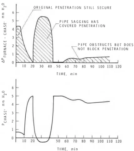
The factor influencing the outcome of these chase tests was found to be the pressure within the chase. If the chase was vented, then a pressure gra- dient was established between the chase and the furnace resulting in failure. If the chase was not vented, then no pressure gradient was established, and hence, hot furnace gases were not driven into the chase. Figure 10 shows the pressure levels within the chase and as a differential compared to the 0.2-in. (5-mm) WG pressure of the furnace.
In the case of the four vented chases, damage was substantial. In each test, a remnant of pipe remained in the top of the chase. The rest of the pipe had collapsed to the bottom of the chase. In one PVC test and the ABS test,
Plastic Pipe 53 P I P E S U P P O R T R O D \-2 x 5 / 8 " T Y P E X G Y P S U M W A L L B O A R D 1 " L A T E R A L 5 / 8 " T Y P E X G Y P S U M W A L L B O A R D 4 " S T E E L S L E E V E 5 " L O N G , 2 4 G S T E E L S L E E V E T H E R M O C O U P L E L O C A T I O N
Figure 9. Vertical pipe chase and fake floor construction.
the pipe in the chase was totally consumed. In two PVC tests, the furnace gases had created a path through the PVC ash, thus exposing the penetra- tion. Figure l l ( a ) shows the temperatures recorded in the air space of the chase just above the penetration, approximately 10 in. (25 cm). The abrupt rise in the graphs reflects the creation of an open path for furnace gases. The lower temperatures for Test B-11, Figure l l ( a ) are the result of restricted venting for that test.
The nonvented chases were constructed so that all joints were sealed. All three tests ran for the full two hours. In one ABS test, the pipe merely col-
54 Fire Technology
lapsed along its axis creating a seal against venting; in a second ABS test the same thing occurred, but the pipe stretched so that the fitting, which had been located 21 in. (53 cm) above the floor, ended up resting over the penetration. In a PVC test, the pipe left a zigzag ash across the chase. Figure l l ( b ) shows the lower temperatures reached in these nonvented chases.
The damage to the chases was in accordance with the temperatures reached. In the vented chases, the studs were burning and the gypsum board either charred or burned through just above the floor penetration. In the nonvented chases, damage only occurred with the PVC test, where the studs were charred a t the bottom. With the ABS tests, the only result was the deposit of a layer of soot on the inside of the chase. Figure 12 presents temperature from a thermocouple location on the gypsum board, 4 in. (102 mm) from the base.
The photographs in Figure 13 illustrate conditions inside nonvented chases after the tests.
0 CU I O R I G I N A L P E N E T R A T I O N S T I L L S E C U R E E 6 P I P E S A G G I N G H A S
COVERED
P E N E T R A T I O N I P E O B S T R U C T S B U O T B L O C K P E N E T R A D O E S 0 N T I M E , r n i n T I M E , m i nPlastic Pipe - 0 3 " A B S - T E S T B - 1 4 ( T . C . A T 1 0 " ) 3 " P V C - T E S T B - 1 1 ( T . C . A T 2 4 " ) A 3 " P V C - T E S T 8 - 1 5 ( T . C . A T 1 0 " ) - A 3" P V C - T E S T 8 - 1 7 ( T . C . A T 1 0 " )
I
T I M E , rninFigure ll(a). Air space temperature in lower chase (vented chases).
MECHANICAL
SHUTOFFSAs in the case of horizontal pipe, a mechanical device can be used to create a seal. Two assemblies were tested, both being based on designs patented by Wise et al.'
The double flapper device shown in Figure 14 works in the same manner as the equivalent horizontal device discussed earlier. The two flappers close sequentially, creating a positive seal against the flow of furnace gases. Some warpage occurred at the hinge on the exposed end of the device. As this occurred on a couple of tests, there is indication that material selection is more important in the vertical situation than in the horizontal.
A guillotine type slide valve assembly for 4-in. (102-mrn) pipe is shown in Figure 15. This type of device was tested with both 34x1. (75-mm) and 4-in. (102-mm) ABS and PVC pipe. I t consisted simply of a frame and a sliding plate, made of '/,-in. (3-mm) steel plate. The drive force was provided by weights suspended over the side of the furnace. Any drive force of equal strength would perform in a similar manner provided that it does not in- terfere with the movement of the plate.
56 Fire Technology
0 3 " A B S - T E S T B - 1 2 3 " A B S - T E S T B - 1 3
A 3 " P V C - T E S T B - 1 6
T I M E , m i n
Figure ll(b). Air space temperature in lower chase (nonvented chases).
This device, like its counterpart for horizontal pipe applications, relied on the temperatureviscosity properties of thermoplastics to function prop- erly. As the pipe softened because of the flow of furnace gases through the pipe, the force of the slide plate caused the pipe to pinch off. Insufficient force would allow either the residual ash from PVC to hold the plate open or softened ABS to collapse on the assembly, holding the plate open. Both situations will lead to ignition of the pipe. Weights of approximately 2,155 g
(4.75 Ib) for 3-in. (75-mm) pipe and 3,420 g (7.5 lb) for 4-in. (102-mm) pipe
were found to be sufficient to operate the device. With these weights, com- plete closure occurred a t 39 min and 25 min for 3-in. (75-mm) PVC and ABS
respectively, and within 22 min for both 4-in. (102-mm) PVC and ABS.
Because the pipe above the slide heated up initially, some expansion and warpage occurred. The cooling that followed the closing of the slide allowed the pipe to contract away from the assembly so that no contact existed. Because the slide directly covered an open penetration, it reached elevated temperatures. Figure 16 shows the temperature record for Test B-24, 4-in. (102-mm) ABS. Thermocouple No. 8 was located in the top of the plate,
Plastic Pipe
Z O O
T I M E , rnin
Figure 12. Outside surface of chase on gypsum wallboard (4 in. from base).
I l l l l l l I I I 1 - N O N - V E N T E D C H A S E S - a-• T E S T 8 - 1 2 ( A B S ) - 0-0 T E S T 8 - 1 3 ( A B S ) - a-n T E S T 8 - 1 6 ( P V C )
I
- O-O-o- o - o -o/~-!' _a-0-8T-I
- . n P d - - * - * -.-.-.-.
--. --&A- 1 1 1 1 1 1 1 1 1 1 1 - p - V E N T E D C H A S E Sd
I - : l - *-o T E S T 8 - 1 1 I P V C ) i I - 1 0 " F R O M B A S E i I -.-.
T E S T 8 - 1 4 ( A B S ) i I I - 0-0 T E S T 8 - 1 5 ( P V C I ! I - - n---..n T E S T 8 - 1 7 ( P V C I;
i Ir -
I 0 - I - Ie
l - I f - I - I - d .A..-
,'1" a-' - . - . ~ $ - 8 ~ e 5 = ~ e - - &-x&#z-ziF-
-* - -0--
* / w-
.--&CW I I I I I I I I I I Idirectly over the penetration, while thermocouple No. 4 was located 3 in. (75 mm) away and not over the penetration.
C O N C L U S I O N S
Under conditions of positive pressure, it is evident that some means of creating a seal is required to prevent flame or hot gases from escaping the involved compartment.
In the case of lateral penetrations of vertical walls, the tests indicate two solutions, those being the use of a sleeve mounted a t an angle of 45" from the vertical and the use of a mechanical shutoff device.
The sleeve penetrating the wall downwards a t a 45" angle allows PVC to create a plug because of the intumescent and ash-forming characteristics of PVC. This situation exists for both 1%-in. (38-mm) and 3411. (75-mm) sizes. With a standard two-hour wall, a seal can be maintained for the full two- hour period. In the reverse situation, where the sleeve penetrates the wall
58 Fire Technology
Figure 13. Nonvented chase tests: (a) 3-in. A B S ; (b) 3-in. ABS; (c) 3-in. PVC. Photographs taken at conclusion o f 2-hour test.
Plastic Pipe
Figure 14. Double flapper device for vertical pipe.
118" STEEL P L A T F L A P P E R H I N G E AND S U P P O R T 4" P I P E I h B S O R P V C t T O P V l E W 0
-
1 2 3 Scale - In I T . C . S I D E V l E WFigure 15. Slide valve assembly for vertical pipe.
upwards at
a
45' angle, the integrity of the partition is maintained as long as the unexposed side is nonvented. This has only been demonstrated for1 %-in. (38-mm) pipe.
60
Fire Technology - o T . C . 8 3 6 " F R O M L E A D I N G E D G E O F S L I D E P L A T E T . C . 4 6 6 " F R O M L E A D I N G E D G E - O F S L I D E P L A T E T . C . 6 U N D E R A S S E M B L Y T . C . 7 A I R S P A C E - T O P O F S T A C K T I M E , m i nFigure 16. Slide valve assembly, Vertical Test B-24, 4-in. ABS.
shutoff devices were both studied. The principal difficulty encountered with single shutoff devices lay in the reliability of a single metal-to-metal seal. Under positive pressure conditions, leakage of furnace gases occurred and caused ignition of the pipe on the unexposed side of the shutoff. The double flapper device discussed earlier resolves this problem and allows protection of the system for two hours for both PVC and ABS pipe. In this assembly, as in all lateral assemblies, the fit of the sleeve through the wall was snug, and the joint was carefully cemented. The assembly was also supported so that it did not rely on the pipe to hold it in place.
For vertical pipe, there also appear to be some solutions, notably the use of mechanical devices. The chase tests indicate that construction of a sealed chase offers protection against fire spread; however, it seems improbable that it would be possible to assure such a construction in normal building practice. I t is noteworthy, however, that the damage sustained in the vented chases was restricted to the lower section of the chase. The chase tests seem to indicate, therefore, that damage in unprotected penetrations could be restricted to the floor above the fire compartment. These chase
Plastic Pipe
tests indicate quite clearly the differences encountered with positive pressure testing.
Both double and single shutoff devices created effective seals. The leakage problems encountered with single shutoff devices for horizontal pipe were not encountered with the slide plate assembly. This is probably a result of the orientation of the device and of its weight. The same explana- tion can be offered as the cause of warping in the double shutoff device for vertical pipe. Careful design and selection of materials could undoubtedly eliminate this problem.
With a view to future design of assemblies, the following general com- ments are offered. All these proposed solutions, with the exception of the
45" sleeve, rely on the fact that thermoplastic drain, waste, and vent pipes soften at temperatures well below the ignition temperature of the materials. This softening allows some weighted or otherwise driven device to crimp the pipe and initiate a seal. As the material heats further, the slide or flap- per completes its travel, leaving a metal barrier between the exposed com- partment and the adjacent compartment. In the moments before a seal is created, hot combustion products are vented through the plumbing system. This produces two effects:
Warpage because of the high coefficient of expansion for plastics; and Possible bursts of flame at the end of the vent system.
The warpage of the pipe in the vertical applications can cause mechanical devices to be displaced unless they are firmly anchored. The solution for the slide plate assembly was to leave a small space between the base plate and the pipe, thus allowing the pipe to deflect without interfering
j
with the device. After a seal was created with all mechanical devices, theI pipe cooled and contracted. Because a permanent deflection was established
I
in the pipe, this contraction caused the pipe to retract from the deviceresulting in no contact between metal and plastic.
The speed of operation of the device seemed significant. With the weights mentioned for the slide valve assembly, a couple of bursts of flame occurred above the top of the stack where furnace gases mixed with the air. When less weight was used, the pipe became very soft and sagged badly. If insufficient force is used, the stack is left unprotected and ignition would be probable.
These test results reveal that even under the most adverse conditions, plastic pipe can penetrate fire separations without propagating fire beyond the separation. The devices tested here would require refinement before they could be considered practical.
I
R E F E R E N C E S' McGuire. J. H., "Penetration of Fire Partitions by Plastic DWV Pipe," Fire Technology,
Vol. 9, No. 1 (Februar 1973), pp. 5-14.
Tamura, G. T., "&mputer Analysis of Smoke Movement in Tall Buildings," ASHRAE
Fire Technology
Draemel, R. B. and R. B. Williamson, "Fire Tests on Six-inch Wood Stud Fire Rated Walls with Plastic DWV Plumbing Systems," University of California, Berkeley, November
1976.
' Wise, E. H. et al, U. S. Patents Nos. 3,678,634 and 3,726,050; July 25,1972 and April 10,
1973.
NOTE: This work was done under the NRC Fellowship arrangement and is ublished with
the approval of the Director. Division of Building Research, and a y pwit&n the Plastic
This publication is being distributed by the Division of Build- ing Research of the National Research Council of Canada. I t should not be reproduced in whole or in part without permis- sion of the original publisher. The Division would be glad to be of assistance in obtaining such permission.
Publications of the Division may be obtained by mailing the appropriate remittance (a Bank, Express, or Post Office Money Order, or a cheque, made payable to the Receiver General of Canada, credit NRC) to the National Research Council of Canada, Ottawa. KIA 0R6. Stamps are not acceptable.
A list of all publications of the Division is available and may
be obtained from the Publications Section, Division of Build- ing Research, National Research Council of Canada, Ottawa.