HAL Id: hal-00852836
https://hal.archives-ouvertes.fr/hal-00852836
Submitted on 21 Aug 2013
HAL is a multi-disciplinary open access
archive for the deposit and dissemination of
sci-entific research documents, whether they are
pub-lished or not. The documents may come from
teaching and research institutions in France or
abroad, or from public or private research centers.
L’archive ouverte pluridisciplinaire HAL, est
destinée au dépôt et à la diffusion de documents
scientifiques de niveau recherche, publiés ou non,
émanant des établissements d’enseignement et de
recherche français ou étrangers, des laboratoires
publics ou privés.
Piezoelectric sensing coating for real time impact
detection and location on aircraft structures
Jean-Fabien Capsal, Charlotte David, Eric Dantras, Colette Lacabanne
To cite this version:
Jean-Fabien Capsal, Charlotte David, Eric Dantras, Colette Lacabanne. Piezoelectric sensing coating
for real time impact detection and location on aircraft structures. Smart Materials and Structures,
IOP Publishing, 2012, vol. 21, pp. 1-7. �10.1088/0964-1726/21/5/055021�. �hal-00852836�
Any correspondence concerning this service should be sent to the repository administrator:
[email protected]
DOI:10.1088/0964-1726/21/5/055021
Official URL:
http://dx.doi.org/10.1088/0964-1726/21/5/055021
This is an author-deposited version published in:
http://oatao.univ-toulouse.fr/
Eprints ID: 8761
To cite this version:
Capsal, Jean-Fabien and David, Charlotte and Dantras, Eric and Lacabanne,
Colette Piezoelectric sensing coating for real time impact detection and location
on aircraft structures. (2012) Smart Materials and Structures, vol. 21 (n° 5). pp.
1-7. ISSN 0964-1726
O
pen
A
rchive
T
oulouse
A
rchive
O
uverte (
OATAO
)
OATAO is an open access repository that collects the work of Toulouse researchers and
makes it freely available over the web where possible.
doi:10.1088/0964-1726/21/5/055021
Piezoelectric sensing coating for real time
impact detection and location on aircraft
structures
Jean-Fabien Capsal
1, Charlotte David
2, Eric Dantras
2and
Colette Lacabanne
21LGEF, INSA Lyon, 69621 Villeurbanne, France
2Physique des Polym`eres, CIRIMAT, Institut CARNOT, Universit´e Paul, Sabatier 31062 Toulouse Cedex 09, France
E-mail:[email protected]
Abstract
Flexible, light weight and low cost electroactive coating has been fabricated by the dispersion of inorganic ferroelectric submicron particles in a polyurethane matrix. BaTiO3particles have
a mean diameter of 300 nm. The poling process and the influence of volume fraction of BaTiO3on the piezoelectric activity of the coating have been reported. This spray coating has
been realized on 1.6 × 1.6 m2poly(epoxy)/carbon fiber reinforced composite. Impact
detection has been also performed. A well-known cross correlated algorithm has been successfully employed to localize impact in a 90 × 90 cm2area of the composite. (Some figures may appear in colour only in the online journal)
1. Introduction
During recent years, much attention has been paid to the detection and location of high impact energies. They can be responsible for delamination of the composite section on aircraft [1, 2]. Due to its low weight, the percentage of polymeric matrix composite used has increased; thus to avoid the risk of delamination, the detection and location of impacts has become crucial. Many works have been devoted to structural health monitoring, but this useful technique requires significant instrumentation and cannot be applied on a wide scale [2]. Piezoelectric materials are commonly used for impact detection. Barium titanate (BT) is one of the most used lead free piezoelectric ceramics, known for its high permittivity, high piezoelectric and pyroelectric properties [3]. However, ceramic materials are fragile. Ferroelectric polymers such as P(VDF) [4], P(VDF-TrFE) [5], PA 11 [6] and PA 6,9 [7] have been investigated. These materials have a ductile mechanical behavior, low dielectric permittivity and good piezoelectric properties which make these organic materials efficient as ferroelectric ceramics [8]. The most restrictive aspect of ferroelectric polymers is the high electric fields required to reach their macroscopic piezoelectric properties [9]. To overcome this issue and to
increase the polymers’ electroactive properties, inorganic fillers have been introduced in the organic matrix to form hybrid ferroelectric composites [10]. Most of these works based on submicron fillers concern P(VDF-TrFE) based composites [11].
This study is focused on the fabrication of an aeronautical sensing coating. We propose giving a piezoelectric behavior to a polyurethane matrix composite by insertion of BT particles. Polyurethane spray coating technology is well known in the aeronautical industry. Since the tetragonality of BT decreases with particle size [8], 300 nm diameter particles have been chosen. The challenge is to ensure a synergy between the electroactive properties of the ceramic and the attractive engineering behavior of polyurethane. Furthermore, the feasibility of real time location on aircraft polyepoxy/carbon fiber reinforced composite (CFRC) with a cross correlation technique [12] is reported.
2. Experimental section
2.1. Materials and sample preparation
Piezoelectric composites were fabricated from the dispersion of inorganic ferroelectric barium titanate submicron particles
(Inframat Materials R) into a water based polyurethane
(Mapaero R) matrix. Barium titanate particles have a 300 nm
mean diameter. The required volume fraction (φ) of inorganic phase was mixed with 5 g of acrylic resin and 4 ml of water. The suspension was submitted to ultrasound for 30 s. Then, the isocyanate was added and the mixture was stirred for 5 min. The final coating was sprayed onto the studied substrate and polymerized overnight at 60◦C. The film was 100 µm thick. The dispersion of barium titanate in the polymeric matrix was checked by scanning electron microscopy (SEM). Cryo-cut images showed a homogeneous dispersion at nanometric scale until a volume fraction of 45%. In this study a low volume fraction has been chosen to maintain the good mechanical properties of the coating. Conductive electrodes (silver paint) were deposited. The poling process of the composite was carried out by applying a dc electric field at 80◦C for 30 min and cooling at room temperature. Then, the field was turned off and the sample was short-circuited for 5 min. In order to remove the internal stress induced during poling, the sample was allowed to relax for 1 day. More details on the dispersion and poling protocol can be found in an extensive description previously published by the authors [8].
2.2. Methods
Dynamic dielectric spectroscopy (DDS) was performed using a BDS400 covering a frequency range of 10−2–3 × 10⁶ Hz with 10 points per decade. Experiments were carried out with a temperature range from −150 to 150◦C. Dielectric isotherm spectra were measured every 5◦C. Before each frequency scan, the temperature was kept constant to ±0.2◦C.
The real ε′
T and imaginary ε′′T parts of the relative complex
permittivity ε∗
Twere measured as a function of frequency f at
a given temperature T.
Piezoelectric measurements were carried out using a PM 200 piezometer supplied by Piezotest R
(UK), with a force of 0.25 N at 110 Hz frequency. The piezoelectric coefficient d33
was measured along the direction of the polarizing field. It is defined by the following relationship:
P = d33σ (1)
where P is the polarization (C m−2)and σ is the applied stress
(N m−2).
For detection and location experiments, the coating sensor was connected to a current to voltage converter and amplifier (DJB Instruments R
, sampling frequency fs =
12 kSa s−1, amplifier gain ratio G = 0.316 g V−1). The signal was transferred to an oscilloscope. The impacts were performed using a 1.6 kg ball dropped from a height of 10 cm to 1 m. The cross correlation technique has been extensively used for location parameter estimation. Ing et al [13] have already demonstrated that the signal records by a piezoelectric sensor can be expressed as the convolution product between the emitted signal e(t) and the impulse response of the sensor h(t):
S(t) = e(t) ⊗ h(t). (2)
By taking into account the working frequency bandwidth, the emitted signal can be approximated by a delta function δ(t). Then, the signal measured by the sensor can be expressed as the impulse response between the sensor location S and the impact point P so that each impact location has a unique response:
S(t) ∼= hSP(t). (3)
The challenge is to be able to apply this method to a non-homogeneous and true aircraft CRFC. To perform the cross correlation technique, a Labview R
program was written. In a first step, impacts performed at various locations were stored in a data bank. The impacts were taken every 10 cm in the x and y directions and they led to a 100 point databank (white points in figure 3). The length between each impact of the databank determines the resolution of the location. In order to decrease the storage requirement this specific distance can be chosen shorter. From an industrial point of view, it is not necessary to locate an impact on an aircraft with such resolution. In a second step, the same CFRC was impacted with a 16 mg ball anywhere in this 90 × 90 cm2 area. The recorded impact to locate was then correlated to the databank and the correlation index CI was reported on a 3D graph. For high energy impact measurements, a 1.6 kg ball was used. Location measurements were also performed with a 1.6 mg metallic ball in order to demonstrate the good sensitivity of the sensor.
3. Results and discussion
Table 1 summarizes the advantages/disadvantages of con-ventional and hybrid inorganic and organic piezoelectric materials. Inorganic ceramics such as PZT are known for their very high piezoelectric strain constants and electromechanical coupling coefficients. The high dielectric permittivity of PZT ceramics leads to a low piezoelectric voltage constant indicating a low sensitivity for open circuit measurements. In spite of the excellent thermal stability of its piezoelectric properties, this material is not suitable for high energy impact sensors due to the fragile behavior and poor impact resistance of ceramics.
Intrinsic piezoelectric polymers such as P(VDF) and P(VDF-TrFE) possess good piezoelectric properties and are highly sensitive in open voltage measurements. Their ductility allows them to be used in high energy impact sensors. But for impact applications on aircraft structures, the piezoelectric response of the sensor must be thermally stable up to 100◦C which is a strong limitation for the use of piezoelectric fluorinated polymers. Fluorinated polymers have several limits: their poor adhesion to substrates, their price and their difficult poling process (100 V µm−1) required to give a ferroelectric behavior to these polymers.
Piezoelectric 0–3 composite has a low piezoelectric activity and a low dielectric permittivity. It gives rise to a high piezoelectric voltage constant that makes it suitable for open circuit measurements. The g33 sensitivity is found to
be higher than that for PZT or BaTiO3 bulk ceramics even
Table 1. Comparison of piezoelectric strain constant d33, relative dielectric permittivity ε33(room temperature and 1 kHz), piezoelectric voltage constant g33, electromechanical coupling coefficient kt, impact resistance, thermal stability of piezoelectric strain constant, density ρ, adhesion to substrate, price and processing between inorganic piezoelectrics (PZT), organic piezoelectrics (PVDF and (PVDF-TrFE)) and piezoelectric composites.
Material d33(pC N−1) ε′ 33 g33(mV m N−1) kt(%) Impact resistance d33thermal stability (◦C) ρ(g cm−3) Adhesion to the substrate Price/process
PZT 300 1400 25 50 Bad >300 7 Needs to be glued Cheap/fair
PVDF −30 12.5 271 10–20 Good ∼70 1.8 Bad Expensive/difficult
P(VDF-TrFE) −25 8.5 330 10–20 Good ∼90 1.8 Bad Expensive/difficult
Polymer BaTiO30–3 composite
0.5–5 2.5–10 5–45 1–5 Good 130 1.05–1.65 Good depending upon
the matrix
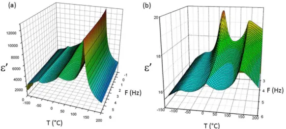
Figure 1. Real part of the dielectric permittivity as a function of temperature and frequency for (a) the bulk and (b) 300 nm particles.
Figure 2. (a) The piezoelectric strain constant d33of PU/BaTiO3300 nm composite with φ = 12% versus the electric field applied during the poling process at T = 80◦C for 30 min; and (b) the piezoelectric strain constant d
33versus the volume fraction of BaTiO3filler.
volume content (∼10% of inorganic submicron particles), the mechanical behavior remains close to the matrix behavior. In this study PU (Mapaero R) was chosen as the matrix due to its
high impact resistance and its good adherence to aeronautical substrate. These composites are cheap and easy to process.
The electroactivity of the composites is dependent on the inherent piezoelectricity of the inorganic filler due to the intrinsic remanent dipoles.
The first point is to confirm the piezoelectricity of submicron BaTiO3 particles. This was carried out by DDS
measurements on BaTiO3bulk and 300 nm powder as shown
in figure 1. In both cases, DDS measurements revealed three dielectric manifestations of solid–solid transitions: respectively the rhombohedral to orthorhombic phase transition, the orthorhombic to tetragonal phase transition and the tetragonal to cubic phase transition (Curie point) around 130◦C. This last transition confirms the piezoelectric behavior for submicron particles.
As previously reported for hybrid polyamide based composites [8], it is important to pay particular attention to the poling process in order to orient the dipoles of the inorganic phase to obtain the optimal piezoelectric activity. The polarization has to be applied at a temperature above the glass transition temperature Tgin order to take advantage of
the large increase of the relative dielectric permittivity (ε′) due to heterogeneities of the nanomaterial [14] and to connect with the local field applied on the inorganic phase [10]. Figure2(a) reports the piezoelectric constant d33 as a function of the
electric field for composites with a BaTiO3 volume fraction
of 12%. The piezoelectric activity increases with the electric field until the critical value of Ec=3 kV mm−1, and then d33
levels off. The value of Ec is consistent with the coercitive
field of the BaTiO3 ceramic [3]. Maxwell–Wagner–Sillars
(MWS) polarization appears at low frequency and high temperature.
The MWS effect is due to the trapping of charge carriers at the interface between inorganic and organic phases. This phenomenon is responsible for an important increase of the composite dielectric permittivity. Thus, at high temperature and low frequency (quasi-static), the local field applied on the submicron particles in the matrix gets close to the field applied on the composite material. An electric impedance matching is observed between the inorganic phase with high dielectric permittivity (for BaTiO3ε′=1500 at T = 25◦C, f = 1 kHz)
and the dielectric permittivity of the organic phase, i.e. the optimal ferroelectric property of the composite is obtained for a field value close to the coercitive field of the bulk ceramic.
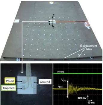
Figure 3. Image of the aeronautical CFRC. The white points indicate the 100 points of the databank forming a 90 × 90 cm2area used for location. Image of the as prepared piezoelectric sensors sprayed on a 1.6 × 1.6 m2and 2 cm thick aeronautical CFRC. An unpoled sensor was taken as reference. The electrical response of an impact performed on an aeronautical CFRC measured by the poled and unpoled sensors.
Polyurethane (PU)/BaTiO3 composites were poled with
a 4 kV mm−1 electrostatic field at 80◦C for 30 min. The influence of the BaTiO3 300 nm volume fraction on the
piezoelectric properties is shown in figure2(b). The evolution of d33with φ is linear. A PU/BaTiO3composite with φ = 12%
has a piezoelectric activity of d33=0.7 pC N−1. Above 12%
in volume, an evolution of the mechanical behavior from ductile to fragile is observed [15]. In the case of high energy impact sensors, the viscoelastic behavior of the matrix has to be optimized.
The optimal formulation of this electroactive coating has been determined according to two criteria: mechanical ductility and measurable piezoelectric coefficient. Thus PU/BaTiO3with a volume fraction φ = 12% has been chosen
for the following study.
A poly(epoxy)/carbon fiber composite with a size of 1.6 × 1.6 m2 and a thickness of 20 mm was used as the substrate. A conductive coating (silver paint) was deposited on this substrate to form the bottom. The bottom electrode was connected to the ground. The sensing layer was sprayed. A conductive top electrode with a 15 × 15 mm2 area
was deposited (figure 3). The following poling procedure was applied: a 4 kV mm−1 electric field at 80◦C for 30 min. The dipoles of the inorganic phases are aligned and give a macroscopic ferroelectric behavior to the sample. A non-poled sample was taken as reference. This reference was fabricated in a similar way to check the validity of the piezoelectric response. Conductive adhesive tape was used to prevent any electromagnetic disturbance. The sensor was located in the center of the substrate and the impact sensitivity was tested along three axes. Two examples of the poled and unpoled response composites are shown in figure 3. Only the poled composite led to an electrical response associated with the mechanical impact. A good signal/noise ratio was obtained.
The measured peak to peak voltage VPP versus the
impact energy is reported in figure 4(a) as a function of direction (labeled zone 1, 2 or 3). The calculated impact energy values range from 0 to 14.5 J. The distance between the piezoelectric sensor and the impact zone was fixed at 35 cm. VPP increases non-linearly with the impact energy.
The evolution of VPP with energy is not dependent on
direction. But for high impact energies, the resulting electric signal is dependent on the impacted direction. This has been attributed to the reinforcement bars fixed on the opposite sides of the poly(epoxy)/carbon fiber composites. These bars parallel to the directions 2 and 3 and give the substrate an inhomogeneous behavior. The impact detection is maximal for a direction that is orthogonal to the reinforcement bars (direction 1). The influence of the impact distance on VPP
Figure 4. (a) Electrical response VPPof the piezoelectric paint versus the impact energy for an impact at 35 cm from the sensor. The direction 1 corresponds to the direction orthogonal to the reinforcement bars and directions 2 and 3 are parallel to the reinforcement bars. (b) Electrical response VPPof the piezoelectric paint versus the distance between the impact and the sensor for an impact energy of E =1.6 J in direction 3.
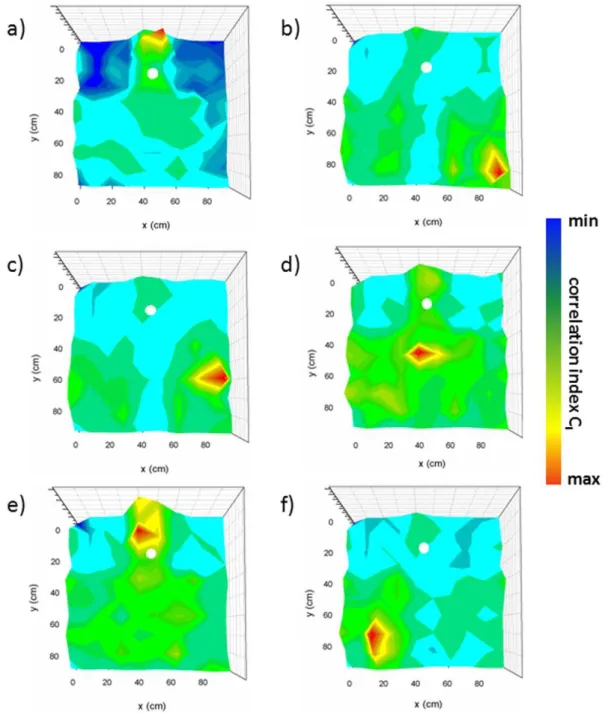
Figure 5. (a)–(f) Real time impact location using the cross correlation technique. The red color reports the maximum correlation index and the white circle shows the active sensing coating location.
is presented in figure4(b). The impact energy at the impact location was maintained at E = 1.6 J. The tests were performed in direction 3. The impact distance ranged from 10 to 70 cm. VPPslightly decreases with the impact distance
due to a damping effect and elastic wave dispersion in the substrate. An 80% decrease of VPPis reported in this distance
range. The inhomogeneity induced by the reinforcement bars gives rise to a significant error.
The evolution of VPP with the impact energy and the
distance allows us to use the conventional triangulation technique for real time location of the impact. But this technique requires at least two sensors for a 2D location and a good accuracy of the measurements. The specific geometry
of the substrate and the reinforcement bars give rise to inhomogeneous stress repartition in the composite after the impact. This is a strong limitation for impact location with the conventional triangulation technique.
For real time location, the cross correlation technique was employed on a 90 × 90 cm2 area of the composite plate described in figure 3. The impact locations using this technique are reported in figures5(a)–(f). The maximum value of the correlation index is reported in red and corresponds to the real location of the impact. Six impacts were performed. A strict coincidence of the calculated location and the real impact area was observed. The resolution depends on the distance between recorded impacts in the databank. The
impact location is given by the maximum correlation index. Since the distance between two points in the databank is 10 cm in the x and y directions, the detected impact is located in a 10 × 10 cm2area.
The high piezoelectric sensitivity of the PU BaTiO3paint
allows the sensor to be placed on the rear face of the CFRC plate. In this way, the effect of temperature variation on the aircraft skin should be minimized. Nevertheless, tests have actually been performed to determine the thermal stability of the impact database.
4. Conclusion
An electroactive coating for real time impact location on aeronautical CRFC plate has been realized. This sensitive nanomaterial is light weight compared to bulk ceramic, easy to mold and impact resistant. Piezoelectric composites have been fabricated from the dispersion of 300 nm BaTiO3 in a
polyurethane matrix and have been used as recovery sensors. The optimal composite has an inorganic volume fraction of 12%; the ductility of the matrix and the piezoelectric activity are maintained. The piezoelectric sensitivity of this electroactive nanomaterial has been demonstrated in a wide impact energy and distance range. Due to the heterogeneity of stress repartition in the composite plate a cross correlation technique has been used and successfully employed for locating the impact.
Acknowledgments
This work was supported in part by DGCIS and R´egion Midi-Pyr´en´ees under the NACOMAT program. The impact detection and location experiments were carried out on a central section of Airbus composite provided by Dr Jean-Michel Bergerat from Airbus France.
References
[1] Soutis C and Curtis P T 1996 Prediction of the post-impact compressive strength of cfrp laminated composites Compos. Sci. Technol.56 677–84
[2] Hufenbach W, Gude M and Heber T 2009 Development of novel piezoceramic modules for adaptive thermoplastic composite structures capable for series production Sensors ActuatorsA156 22–7
[3] Roberts S 1947 Dielectric and piezoelectric properties of barium titanate Phys. Rev.71 890–5
[4] Kawai H 1969 The piezoelectricity of poly(vinylidene fluoride) Japan. J. Appl. Phys.8 975–6
[5] Samara G A and Bauer F 1992 The effect of pressure on the molecular relaxation and phase transition of the
ferroelectric copolymer Ferroelectrics135 385–9
[6] Mei B Z, Scheinbeim J I and Newman B A 1993 The ferroelectric behaviour of odd-numbered nylons Ferroelectrics144 51–60
[7] Capsal J-F, Dantras E and Lacabanne C 2010 Dielectric relaxation and ferroelectric behaviour of even-odd polyamide PA 6,9 Polymer51 4606–10
[8] Capsal J-F, Dantras E, Laffont Lydia and Lacabanne C 2010 Nanotexture influence of BaTiO3particles on piezoelectric behaviour of PA 11/BaTiO3nanocomposites
J. Non-Crystall. Solids356 629–34
[9] Lovinger A J 1983 Ferroelectric polymers Science
220 1115–21
[10] Furukawa T, Fujimo K and Fukada E 1976 Electromechanical properties in the composites of epoxy resin and PZT ceramics Japan. J. Appl. Phys.15 2119–29
[11] Jinhua L, Ningyi Y and Chan H L W 2002 Preparation of PLCT/P(VDF-TrFE) pyroelectric sensor based on plastic film substrate Sensors Actuators A100 231–5
[12] Catheline S, Fink M, Quieffin N and Ing R K 2007 Acoustic source localization model using in-skull reverberation and time reversal Appl. Phys. Lett.90 063902
[13] Ing C K, Quieffin N, Catheline S and Fink M 2005 In solid localization of finger impacts using acoustic time-reversal process Appl. Phys. Lett.87 204104
[14] Kremer F and Sch¨onals A 2003 Broad Band Dielectric Spectroscopy(Berlin: Springer)
[15] Capsal J-F, Dantras E and Lacabanne C 2010 Dynamic mechanical behavior of Polyamide 11/Barium titanate ferroelectric nanocomposites Polymer51 5207–11