HAL Id: hal-01737098
https://hal.archives-ouvertes.fr/hal-01737098
Submitted on 19 Mar 2018
HAL is a multi-disciplinary open access
archive for the deposit and dissemination of
sci-entific research documents, whether they are
pub-lished or not. The documents may come from
teaching and research institutions in France or
abroad, or from public or private research centers.
L’archive ouverte pluridisciplinaire HAL, est
destinée au dépôt et à la diffusion de documents
scientifiques de niveau recherche, publiés ou non,
émanant des établissements d’enseignement et de
recherche français ou étrangers, des laboratoires
publics ou privés.
Hybridization of an aircraft emergency electrical
network: Experimentation and benefits validation
Krzysztof Rafal, Benoît Morin, Xavier Roboam, Eric Bru, Christophe Turpin,
Hubert Piquet
To cite this version:
Krzysztof Rafal, Benoît Morin, Xavier Roboam, Eric Bru, Christophe Turpin, et al.. Hybridization of
an aircraft emergency electrical network: Experimentation and benefits validation. 2010 IEEE Vehicle
Power and Propulsion Conference, Sep 2010, Lille, France. pp.0, �10.1109/VPPC.2010.5728987�.
�hal-01737098�
O
pen
A
rchive
T
OULOUSE
A
rchive
O
uverte (
OATAO
)
OATAO is an open access repository that collects the work of Toulouse researchers and
makes it freely available over the web where possible.
This is an author-deposited version published in :
http://oatao.univ-toulouse.fr/
Eprints ID : 19618
To link to this article : DOI:10.1109/VPPC.2010.5728987
URL :
http://dx.doi.org/10.1109/VPPC.2010.5728987
To cite this version : Rafal, Krzysztof and Morin, Benoît
and
Roboam, Xavier
and Bru, Eric
and Turpin, Christophe
and
Piquet, Hubert
Hybridization of an aircraft emergency electrical
network: Experimentation and benefits validation. (2010) In: 2010
IEEE Vehicle Power and Propulsion Conference, 1 September 2010 - 3
September 2010 (Lille, France).
Any correspondence concerning this service should be sent to the repository
Hybridization of an aircraft emergency electrical
network: experimentation and benefits validation
K. Rafal
Institute of Control and Industrial Electronics Warsaw University of Technology Koszykowa 75, 00-662 Warsaw, Poland
rafalk@isep.pw.edu.pl
B. Morin, X. Roboam, E. Bru, C. Turpin,
H. Piquet
Université de Toulouse, LAPLACE UMR CNRS INPT UPS ENSEEIHT, 2 Rue Camichel 31071 Toulouse Cedex France
email: name@laplace.univ-tlse.fr
Abstract— This paper proposes a structure and two strategies for hybridization of a RAT (Ram Air Turbine) with supercapacitor storage. The structure consists in coupling a High Voltage DC (HVDC) source (RAT) with a low voltage storage device through a specific topology of bidirectional DC-DC static converter. The energy management strategies consists in entrusting the storage with the “high frequency” harmonics of the load power while the RAT only produces the average power: the RAT sizing and its mass can then be reduced. Lab test bench architecture, control strategy, topology of the converter and experimental results are presented in this paper.
Keywords- power source, hybridization, Ram Air Turbine (RAT), Supercapacitor, DC/DC bidirectional static converter.
I. INTRODUCTION
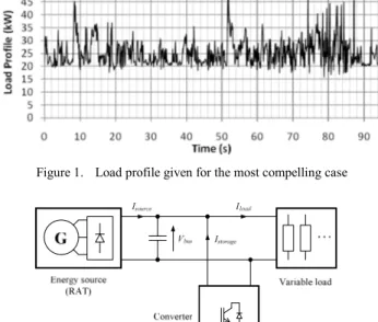
In the context of MEA (More Electrical Aircraft), the importance of electricity sharply increases in aeronautic systems. Aircrafts are prone to various failures, which have to remain acceptable through reliable and redundant systems. Emergency systems are then installed on board to ensure safe operation and comply with regulations, even in case of drastic failure as total engine fault [1], [2] [4]. The increasing electricity demand in modern aircrafts allows changing the actual emergency appliances, using almost exclusively electrical energy in the case of total power loss during engines failure. During this operation, energy generation is often ensured by a high speed wind turbine (Ram Air Turbine - RAT) that unfolds in case of engine failure. This turbine is currently sized to provide the maximum power that aircraft may require during emergency mission. In such a case, the main power demand is due to flight control actuators: the movement of flight control surfaces is carried out by EHAs (Electro-Hydraulic Actuators) or EMAs (Electro Mechanical Actuators) [3] which need high power during short period of time. This results in a very intermittent consumption profile where the peak power is about twice higher than the average power [4]. This power cycle is given for the most compelling case, when the aircraft is approaching the landing phase at low altitude: RAT power is minimum due to low aircraft speed while many flight control actuators are operated simultaneously. The mission profile considered in the following experiment is shown on the Fig.1.
A recent study [4] has demonstrated that significant reduction in weight and volume of the whole emergency system can be obtained by hybridizing the turbine with a
storage device: about 30% mass reduction could be expected on the system. Actually, with regard to this class of load profile, the best weight-power ratio and safe operation for storage appliances is given for supercapacitors [5]. The issue of hybridization consists in providing the average power and losses by the main power supply (i.e. RAT) while transient power is covered by the storage (supercapacitors), this operation is called power sharing [6],[7]. The structure of hybridized system is presented on Fig. 2. Recent studies [4] have shown that several hybridization strategies can be applied to manage energy to optimize the system efficiency. Two different strategies have been analyzed by simulations interfacing RAT and storage device modeling and its load. This concept has been tested on a specific test bench presented on Fig.10 for which main results are presented in the paper.
A specific topology of bidirectional DC/DC static converter has been developed enabling hybridization between high voltage power supply and low voltage storage device (supercapacitors or accumulators) till 28V DC which is the avionic bus standard.
Figure 2. Scheme of hybrid emergency electrical network
II. HYBRIDIZATION STRATEGIES
Two strategies are studied for hybridization of the RAT generator with supercapacitors, both having individual advantages and drawbacks [4]:
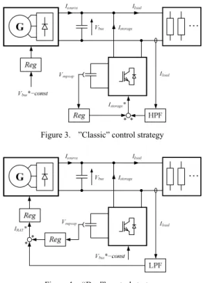
‘classic’ (Fig. 3) utilizes the RAT as a voltage source and storage bank as a transient current source. The reference current for storage device is the high-pass filtered load current (HPF), while excitation current of the generator is “classically” controlled to keep constant the HVDC voltage at the output of the diode rectifier. Due to the high pass filtering effect, the storage sub system only provides the power ripple with harmonics beyond the filter cut off frequency. The RAT only delivers the average power and low frequency harmonics;
‘dual’ (Fig. 4) utilizes the RAT as a controlled current source, while storage sub system is responsible for controlling the HVDC-bus voltage. In this case, the reference current for turbine is the low-pass filtered load current (LPF). This dual strategy has been proved [4] to be better than the ‘classic’ one in terms of energy transfer as the current control operation of RAT sub system allows maximizing its power when it is required by the load and/or the storage. As for classical wind turbine systems, this strategy allows MPPT (Maximum Power Point Tracking) of the Ram Air Turbine. Optimizing the energy transfer leads to minimize the RAT sizing and consequently the whole system weight.
Dynamics of power sharing could be adjusted by choice of the cut-off frequency of the filter: smaller frequency causes less variation in RAT current, but high utilization of stored energy. Final choice of power sharing frequency should take into account the load profile and nominal rating of storage device (stored energy) and turbine (peak current). In [4], a complete study that optimizes sizing (diameter adaptation) of the RAT device together with the storage definition has been proposed.
In fact, even if only harmonic currents (null average power) have to be provided by supercapacitors, losses in the storage device as in the interfacing converter provoke a slow decrease of the state of charge. Then, a special control action has to be added to keep supercapacitors conveniently charged. Typically, voltage must vary between 0.5 and 1.0 Vn, as 75% of stored
energy is utilized. For this case, average voltage of operating supercapacitor should be kept around 0.75 of nominal voltage (Vn). To control this voltage, an additional loop is introduced in
the system (denoted Reg in Figs. 3 and 4). In the first strategy (“classic”), voltage controller imposes additional slow dynamic current added directly to the storage reference, while in the second (“dual”) strategy slow balancing current is added to the RAT reference.
Figure 3. ”Classic” control strategy
Figure 4. “Dual” control strategy
III. STORAGE INTERFACING CONVERTER
To interface HVDC bus with various low voltage or very low voltage storage devices, a unique topology of static converter was developed (Fig. 5) by LAPLACE and built by CIRTEM [8]. The converter is designed to meet specific needs for hybrid systems, such as:
high peak current (-90 Ampers to +90 Ampers in the storage device),
high current dynamic, with controlled transient behavior, high voltage gain (Vbus/Vstorage), with capability of
controlling the Vbus voltage for startup or in case of high
voltage generator fault condition. The converter is able to work with a storage voltage from some Volts to Vbus that allows a large choice storage nature. Thus the bus voltage is between Vstorage and 650V which allows a large choice of applications.
Each of these requirements has its consequence in the converter design. The structure contains two power modules of triple buck/boost branches switched by IGBT transistors. In each module, the high current capability is obtained by summing the three interleaved inductor currents: PWM signals for each leg are 120 degrees shifted, resulting in an increase of apparent switching frequency and a current ripple reduction (ileft and iright currents).
Figure 5. Topology of the converter interfacing storage and HVDC bus
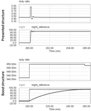
The main advantage of this structure is to allow each branch (left = buck, right=boost) to work with duty cycles around 0,5. For the considered requirements, a classical boost converter would have to work with high modulation index to achieve high voltage gain: as an example, for a 540V HVDC bus (next generations standard avionic voltage [10]) and a 28V battery bank (avionic bus standard [10]), the corresponding duty cycle is 0,948, really near the usual limits [0,05..0,95], which will hardly allow a satisfactory design of the current control loops. This results in slow dynamics of control loops as illustrated on Fig. 6. To avoid this drawback, this topology allows to shift the battery voltage by the Vmid voltage across the
C1left capacitor.
Figure 6. Comparison by simulation between the presented structure an a 3-legs “classical” boost with same control loops and limitations on duty cyles
[0,05..0,95]- VHVDC=540V, Vstorage=28V.
The left power module is used to control Vmid “medium
voltage” with a typical cascaded PI controller structure (Fig. 7). If this voltage is set at:
(
bus bat)
/2mid V V
V = − , (1)
both branches of the converter can efficiently operate with duty cycles close to 0.5. The right power module can operate in two control modes: battery current (as presented on Fig. 7) or HVDC bus voltage control.
Figure 7. Converter control scheme
In this system, the power delivered from the storage sub system to the HVDC bus is:
) ( rightHV leftHV bus
bus V I I
P = − . (2)
Using power balance equations by neglecting converter losses, power can be rewritten as:
) ( bus mid left bus mid bat right bus bus V V I V V V I V P = + − . (3)
Under steady state condition (i.e. stable C1left and C1right
capacitors), Ileft = Iright = Ibat, so:
bat bat bus mid bat bus mid bat bat bus bus I V V V I V V V I V P = ( + − )= . (4)
However, during transients Iright is controlled by fast current
controller, while Ileft is controlled indirectly by slow voltage
controller, which causes delay between current transients. This causes chattering on the power delivered to the bus, as well as oscillations on Vmid voltage. Note that if it is possible to keep
Ileft=Iright, capacitor voltages remain unchanged and power flow
is correct. So, it is natural to force the same current for left and right branches. This can be simply done by adding Ibat*
reference signal to the Ileft current controller (marked by dotted
line in Fig. 7). As the The Vmid voltage is now naturally
balanced, PI controller is only used to set initial voltage and regulate steady state error.
Experiments show a sufficient dynamic of the converter (Fig. 8 and Fig. 9) for achieving hybridization with the load profile given on the Fig. 1.
100 101 102 -6 -4 -2 0 2 4 6 A tt enu at ion I b at (LV D C ) 100 101 102 -100 -50 0 50 Ph as e sh ift I b at ( LVD C )
Figure 8. Bode plot of Ibat/Iref measured in experimental system
0.75 0.8 0.85 0.9 0.95 1 1.05 1.1 1.15 1.2 0 10 20 30 40 Time [s] C urrent [ A ] Ibat Ibus Iref 0.75 0.8 0.85 0.9 0.95 1 1.05 1.1 1.15 1.2 70 80 90 100 110 Time [s] V ol tage [ V ] Vmid
Figure 9. Response experimental system for current step with feedforward.
IV. EXPERIMENTAL TEST BENCH
A. Electrical Network
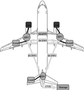
For the experimental validation of hybridization, a test bench has been built in Laplace laboratory [8]. It reproduces a HVDC (High Voltage DC, 540V in the aeronautic context) meshed electrical network dedicated to a future aircraft, as illustrated on Fig. 10. The hearts of the system are three EPCs (Electrical Power Centers) for which HVDC voltage is controlled. Each of them is able to interconnect up to six DC sources and loads with maximum current of 50A. Power exchanges between each EPC is possible with DCPFCs (Direct Current Power Flow Controllers) [9][9]. Three-phase autotransformers with diode rectifiers are used to emulate HVDC power channels. Hybridization is possible by including a static converter in the rear EPC, which interfaces low voltage storage (dozens of volts) with HVDC bus. Whole system is managed by a supervisor based on the dSPACE modular hardware. Power converters used in the presented experiment allow operating at 10kW peak power.
Figure 10. Scheme of meshed HVDC network tested in the LAPLACE lab
The mission profile corresponding to actual loads (flight control actuators and others) as illustrated on Fig.1 is emulated by means of programmable load: a power scale factor (1/5) has been added to fulfill the power range of the test bench.
B. RAT Emulation
The RAT is actually loaded by a synchronous generator for which voltage (or current) is controlled with external excitation. In the case of HVDC network, stator currents are rectified with a three-phase diode bridge to provide energy for DC loads. As the lab is not equipped with actual air turbine, it has to be emulated by means of accessible equipment, the issue being to reproduce the transient behavior of the RAT device: in our case a DCPFC is used to emulate the RAT, this device being able to set a programmable DC current of HVDC voltage. An equivalent DC structure of RAT is considered for the emulator, as described in [4]. The model is simplified – no mechanical dynamics are considered, the aircraft speed is assumed to be constant during the mission cycle of Fig.1. Only electrical dynamics are then modeled.
Electrical scheme of synchronous machine and its DC equivalent are shown on Fig.11. Both excitation and stator are first order RL circuits. Assuming operation at constant speed and unity power factor (due to the diode rectification), relation between excitation current and electromotive force is approximated to be linear [4]. Therefore the whole system is considered as two cascaded first order transfer functions with their respective time constants, as presented on Fig. 12 (on the latter it has been chosen to consider the current delivered by the RAT as the output of the system). To control RAT current or DC bus voltage, a typical cascaded structure of PI controllers is used. The whole structure is implemented in the supervisor system, which calculates the instantaneous value of RAT current or voltage. It is then sent to the programmable static converter (DCPFC, which has a considerably higher bandwidth [9] than the RAT system) to emulate the RAT transient behavior.
Figure 11. Electrical scheme of RAT and its equivalent DC circuit ex ex R sL + 1 DC DC R sL + 1
Figure 12. Dynamic model of RAT used for emulation
C. Supercapacitors
Supercapacitors (also called ultracapacitors or electric double-layer capacitors), are electrical energy storage devices, which offer high power density, extremely high cycling capability, and mechanical robustness. They are the right solution for systems with high instantaneous power demand. These advantages are exploited in the analyzed system – they offer high peak current capability together with low weight. In this experiment modules Maxwell BPAK0058 E015 B01 supercapacitors are used (C=58F, Un=15V).
Electric power drawn from supercapacitors is mainly limited by interfacing converter current limit. Therefore, to achieve desired level of power, several capacitors have to be connected in series to increase voltage level. In this case voltage on each cell can differ and therefore should be measured and controlled. Maxwell supercapacitors offer built-in active balancbuilt-ing circuits to solve this issue. Another issue is the required capacity of energy storage: this need is defined by the the load profile. Parallel connection may be necessary to increase storage capacitance. In this experiment single branch of 9 series-connected modules of 6 supercapacitors is used to fulfill abovementioned requirements (Cs=6,44F, Un=135V).
V. EXPERIMENTAL RESULTS
On the figures below, experimental results of hybridization obtained on the lab test bench are presented. The system is configured as follows:
9 modules of 6 capacitors are connected in series,
storage converter operates with current feedforward compensation,
HVDC bus voltage is controlled to 270V, DCPFC is emulating Ram Air Turbine dynamics, frequency of power sharing filter is set at 0.01 Hz,
Load profile has 5kW average power and 10kW peak power (1/5 ratio vs. actual profile).
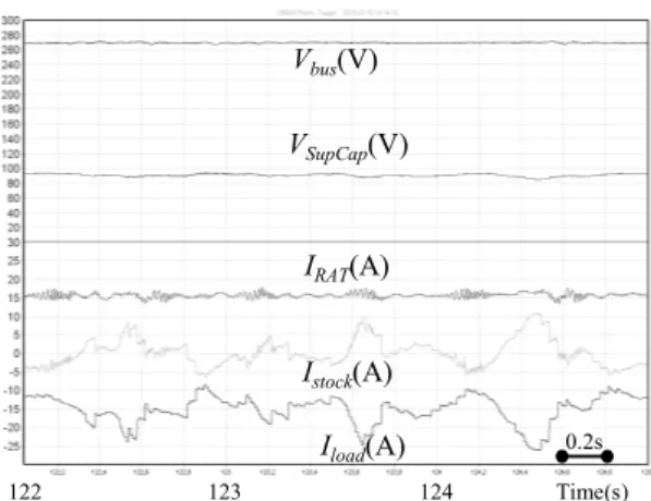
Captured waveforms present HVDC bus and capacitor bank voltages with currents of RAT, storage and load for the two strategies. Fig. 13 and 14 respectively present full load cycle
for ‘classic’ and ‘dual’ strategies. Fig. 15 and 16 present zoom on most dynamic part of profile with high current peaks.
The filtering effect on the RAT current can be observed in all cases that verify the capability of this hybrid system to reduce the RAT sizing. Indeed, as the maximum load current is -25A, the one provided by the RAT is only 15A (i.e. ~60%). Based on these experiments for which the MPPT operation of RAT has not been considered, the reduction effect seems to be the same for both strategies even if the ‘dual’ has been shown in [4] to be optimized in terms of size reduction (weight reduction) capability.
The zoom illustrated on Fig.15 and Fig.16 show that all dynamics of sources are conveniently controlled, especially the supercapacitor state of charge which is kept around its nominal operation along the whole mission profile.
IRAT(A) Vbus(V) VSupCap(V) Istock(A) Iload(A) 100 120 140 160 180 Time(s)
Figure 13. ‘classic’ hybridization with RAT emulation (RAT in voltage mode, storage in current mode)
IRAT(A) Vbus(V) VSupCap(V) Istock(A) Iload(A) 100 120 140 160 180 Time(s)
Figure 14. ‘dual’ hybridization with RAT emulation (RAT in current mode, storage in voltage mode)
122 123 124 Time(s) IRAT(A) Vbus(V) VSupCap(V) Istock(A) Iload(A) 0.2s
Figure 15. zoom on ‘classic’ hybridization with RAT emulation (RAT in voltage mode, storage in current mode)
129 130 131 Time(s) IRAT(A) Vbus(V) VSupCap(V) Istock(A) Iload(A) 0.2s
Figure 16. zoom on dual hybridization with RAT emulation (RAT in current mode, storage in voltage mode)
VI. CONCLUSION
In this paper, two hybridization strategies have been tested on an experimental test bench that interfaces an emulator of RAT device, a storage subsystem equipped with a dedicated interfacing converter connected to a super capacitor bank. The dedicated converter structure allows interfacing a HVDC bus with low or even very low storage voltages with convenient dynamic. The main source (RAT sub system) and the load are connected to a HVDC bus, they physically emulate actual dynamics of the aircraft emergency electrical network. The obtained experimental results confirm theoretical issues obtained in a previous study that have shown the capability of such system hybridized with supercapacitor to significantly reduce the whole weight: the mass reduction had been
estimated to 30%. The dynamic behavior of both strategies (‘classic’ and ‘dual’) is nearly equivalent and the system is kept stable for transient operation. Experiments have especially shown the RAT current filtering effect and the correct state of charge control for supercapacitors. Complementary tests have verified the correct thermal operation of these storage devices along several mission cycles.
ACKNOWLEDGMENT
This study has been involved in the framework of two projects, first in the REMAIN regional project, for which the authors thank the Midi-Pyrénées French region for support and funding, secondly in the national project ISS (Innovative Solution for Systems) project for which the authors thank the DGAC (Direction Générale de l'Aviation Civile) and Airbus France for support and funding.
REFERENCES
[1] P.H. Mellor, S. G. Burrow, T. Sawata, M. Holme, “A Wide-Speed-Range
Hybrid Variable-Reluctance permanent-Magnet Generator for Future Embedded Aircraft Generation Systems”, IEEE trans. on Ind. Appl.,
vol. 41, n°2, March/April 2005.
[2] M. Koerner, “Recent developments in aircraft emergency power”, IEEE conf., IECEC , Las Vegas, NV, 2000.
[3] D. Van Den Bossche, “ More electric control surface actuation – A
standard for the next generation of transportaircraft”, 10th European
Power Electronics and Applications Conference, Toulouse, France, 2003.
[4] O. Langlois, “Conception d’un réseau de secours électrique pour
l’aéronautique”, PhD, Institut National Polytechnique, Toulouse, June
2006 - http://ethesis.inp-toulouse.fr/archive/00000243/.
[5] M. Y. Ayad, M. Becherif, A. Djerdir, A. Miraoui, “Sliding Mode
Control for Energy Management of DC Hybrid Power Sources Using Fuel Cell, Batteries and Supercapacitors”, IEEE conf., ICCEP, Capri,
2007.
[6] J. J. Awerbuch, C. R. Sullivan, “Control of Ultracapacitor-Battery
Hybrid Power Source for Vehicular Applications”, IEEE conf.,
ENERGY, Atlanta, GA, 2008.
[7] L. Gao, R. A. Dougal, S. Liu, “Active Power Sharing in Hybrid
Battery-Capacitor Power Sources”, IEEE conf., APEC, 2003.
[8] www.cirtem.com
[9] A. Berasain; Jesus Lopez; E. Gubia; L. Marroyo; Hubert Piquet “Power
control between two DC buses for on-board systems network stability support”, IECON 2009: 35th Annual Conference of the IEEE Industrial
Electronics Society, Porto, Portugal, 3-5 nov. 2009
[10] C. Baumann “Architecture et gestion d'un réseau continu maillé
haute-tension pour l'aéronautique” PhD, Institut National Polytechnique,