HAL Id: hal-02396326
https://hal.archives-ouvertes.fr/hal-02396326
Submitted on 12 Nov 2020
HAL is a multi-disciplinary open access
archive for the deposit and dissemination of
sci-entific research documents, whether they are
pub-lished or not. The documents may come from
teaching and research institutions in France or
abroad, or from public or private research centers.
L’archive ouverte pluridisciplinaire HAL, est
destinée au dépôt et à la diffusion de documents
scientifiques de niveau recherche, publiés ou non,
émanant des établissements d’enseignement et de
recherche français ou étrangers, des laboratoires
publics ou privés.
Addressing space charge issues in aeronautical DC cables
A. Benyoucef, Laurent Berquez, G. Teyssedre, Eddy Aubert
To cite this version:
A. Benyoucef, Laurent Berquez, G. Teyssedre, Eddy Aubert. Addressing space charge issues in
aero-nautical DC cables. More Electrical Aircraft Congress, (MEA 2019) Toulouse, 06-07 Feb. 2019, Feb
2019, Toulouse, France. �hal-02396326�
Addressing space charge issues in aeronautical DC cables
Amin Benyoucef (1), Laurent Berquez (2), Gilbert Teyssedre (3), Eddy Aubert (4) 1: Laplace, Université Paul Sabatier Bat 3R3, 118 Route de Narbonne 31062 Toulouse
and IRT Saint-Exupéry, 3 Rue Tarfaya 31405 Toulouse, [email protected] 2: Laplace, [email protected]
3: Laplace, [email protected] 4: IRT Saint-Exupéry, [email protected] Abstract
The aircraft of the future will be more electrical and all electrical. Technological evolutions foresee an increase of the DC voltage up to 3 kV or 6 kV with keeping the thickness of insulations to the minimum. This results in a strong increase of the electric field in the insulations and space charge can become an issue for the reliability of the systems. Indeed, space charge accumulation is at the origin of a residual field that modifies the electric field and may lead to a premature aging of the dielectric. Besides, the field distribution in complex structures like multilayers cannot be anticipated under DC as easily as under AC because conductivity is trickier to estimate and varies much more than permittivity. To measure these effects, we propose to develop a test bench adapted to aeronautical cables based on the PEA (Pulsed Electro Acoustic) method. The final aim is to assess the capabilities of current cables to be used for DC voltages in future aircrafts.
Introduction
The increase in the power of the electrical systems of future aircraft goes with an increase of the AC and DC voltages of power networks. For DC systems, the phenomenon of partial discharges, well-known in case of AC voltage, is actively studied [1] with consequences much less as under AC as the frequency of occurrence is strongly reduced. However, other effects, such as space charge accumulation, are to be considered. For the insulation of terrestrial or submarine HVDC energy cable systems, with voltages of several hundreds of kV, the problem of space charge is known and deeply investigated for long. Even if the voltage levels in aeronautics are much lower, an increase of the DC buses beyond 3 kV or 6 kV is foreseen while the insulation thickness is minimized to optimize the mass of the aeronautical network. This means that a significant increase in the electric field in the insulations could occur, possibly to levels where space charges could be accumulated and the field threshold for non-linear conduction be reached. Therefore, space charge effects must be investigated, mastered and taken into account in future technologies. To meet these challenges, our objective is to develop a test bench to measure space charge distributions on aeronautical cables and to estimate the evolution of the electric field distribution in the samples and in particular in multilayer arrangements and to identify the stress regimes where these phenomena occur.
Effect of space charge on the electric field
Electrical insulators never have an ideal behavior. Through different mechanisms of generation and transport, space charge build up can be observed. The space charge is the set of positive or negative charges in the dielectric. In addition, it is possible to distinguish so-called intrinsic charges which are
charges present initially within the dielectric itself or created by electro-dissociation of neutral species and the so-called extrinsic charges which are charges injected from electrodes to the insulator, such as electrons or holes [2].
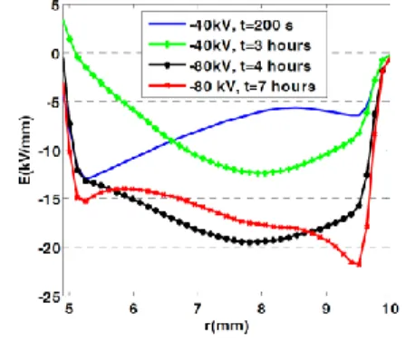
We first provide some typical examples of the effects of space charges in energy transmission cables. Figure 1 shows the electric field distribution in a crosslinked polyethylene (XLPE) insulated model cable, with 5 mm inner radius and 9.5 mm outside radius for the insulation, measured along the insulation radius. The cable was subjected to -40 kV and -80 kV voltages at ambient temperature and different polarization times. The profile obtained short after the polarization at -40 kV/mm is very close to the geometric field distribution. For the other curves, as a function of time and bias voltage, the charge distribution modifies the distribution of the electric field.
Fig. 1: Electric field distribution in model cable stressed under -40 kV and -80 kV at room temperature and different times [3].
While the capacitive field should be greater on the core of the cable, under the effect of charge build-up the electric field is maximum on the outside of cable. One of the reasons can be the radius dependence of
the conductivity due for example to a thermal gradient. The field distribution induced by such process is of the form:
E(r)= Ecr.σ(r)rc.σc (1)
where Ec and σc are the electric field and conductivity
at reference radius rc.
The association of dielectrics is another example where charge build-up is at play. Figure 2 shows a space charge mapping for different applied voltages to a XLPE/EPDM (ethylene propylene diene monomer) bilayer material at room temperature. On ordinate axis on the left, the position in µm is represented (with total thickness 600 µm), on the right is represented the charge density in C/m3 and on the
abscissa the polarization time. The area defined by dotted lines represents the XLPE/EPDM interface. It can be seen that at the interface the charges are positive for average fields less than 15 kV/mm. For an average field between 15 kV/mm and 20 kV/mm, the positive charge density begins to decrease and become negative for fields greater than 20 kV/mm [4].
Fig. 2: Space charge mapping in XLPE/EPDM bilayer materials at room temperature for average fields given on the top scheme. Measurements at 20°C. EPDM to the top; XLPE to the bottom. Color bar provides charge density scale in C/m³ [4].
The observed phenomenon is interface charge between the two materials, so called Maxwell-Wagner effect. This interface charge depends on the relative values of conductivity and permittivity of the two materials:
Σ
s=
1.σ2−2.σ1σ2.d1+σ1.d2 (2)
where ε and d are the permittivity and thickness of materials 1 and 2.
Moreover in the present case, the conductivity and permittivity depend on the temperature and the electric field, which explains the change of sign of the interface charges depending on electro-thermal conditions [4]. Accordingly, the field is maximum in one layer or the other, and by measuring the charge
density distribution, the field distribution can be estimated as well. We discuss below about the occurrence of such process in aeronautic cables. Different methods of measuring space charge Above results were obtained using the pulsed electro-acoustic technique. To measure the space charge density profiles, different principles have been developed over the years. Two categories can be distinguished [5].
Thermal methods consist in creating a thermal perturbation within the sample. The absorbed thermal energy diffuses and generates local deformations and local modifications of the permittivity. These changes move the charges relative to the electrodes creating a current in the outside circuit [6, 7]. The transient current contains information on the quantity and the position of the space charge. A mathematical treatment is necessary to recover the space charge distribution.
Acoustic methods use an acoustic wave to disturb or carry information to quantify the charge amount and position in the material. One main advantage of acoustic methods is the speed of measurement, because it is related to the speed of sound for propagating waves in the material. One of the disadvantages of these methods is the sensitivity to noise [6].
The method chosen to measure the space charge in aeronautic cables is the PEA method (Pulsed Electro Acoustic).
PEA method on cable
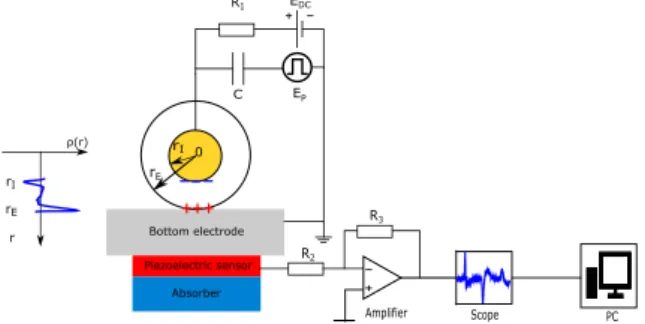
For the first time in the 90’s, a PEA system was introduced for the measurement of the space charge on cable for High Voltage transmission [8, 9]. The method consists in applying a voltage pulse to the sample, producing oscillation of the charges around their equilibrium positions, thus generating acoustic waves. The acoustic waves are then converted into an electrical signal through a piezoelectric sensor and this signal is amplified and digitally processed by a deconvolution algorithm (Fig.3).
Fig. 3: Schematic diagram PEA witch an example of load profile.
The general expression of electrostatic force density
2 4 6 8 10 15 20 30 -30 t(h) E(kV/mm)
in a dielectric material is [10]:
𝑓 = 𝜌. 𝐸 −
12. 𝐸
2. 𝛻𝜀𝑟
−
12
𝛻(𝐸
2
. 𝛾)
(3)
where ρ is the space charge distribution, E the
electric field generated by the static field 𝐸𝐷𝐶 and the
pulse field 𝐸𝑝, ε0 the vacuum permittivity, εr the
relative permittivity of the dielectric and γ the
electrostriction coefficient.
The different contributions are as follows:
- The first term represents the Coulomb force acting on the space charges present in the dielectric.
- The second term represents the force due to the permittivity gradient existing at the interface between two different dielectrics. - The third term represents the effect of
electrostriction.
For a coaxial cable where insulators are considered homogeneous, the second term may be neglected. But the third term cannot be neglected because in coaxial geometry the Laplacien field is divergent. At the IRT Saint Exupery and in collaboration with the LAPLACE laboratory, we are developing a PEA bench for space charge measurement for aeronautical cables. For this we use:
- A HVDC generator HCP350-35000 with a voltage range of -35 kV to 35 kV and a maximum current of 10 mA applied the DC Voltage to the cable conductor
- A pulse generator FPG 2-10NM6 of 1600 V maximum amplitude , 6ns width and 10kHz of repetition rate to 10 kHz
- A of 9 µm thick piezoelectric sensor (PVDF) to convert the acoustic waves into an electrical signal
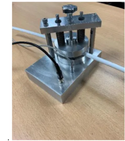
Figure 4 shows the PEA cell that will be used to perform PEA measurements on aeronautical cables.
- .
Fig. 4: PEA cell for space charge measurement for aeronautical DC cables.
The specificity of aeronautic cables
Figure 5 shows a typical example of aircraft cable cross-section in which the insulation is wrapped over the multi-stands conductor designed for avoiding skin effect in the conductor. A Polyimide layer is generally wrapped directly on the conductor and is used because of its high mechanical strength, dielectric and thermal insulation properties. The outer tape of the cable is a fluorinated polymer set for limiting fire issues and arc tracking.
The PEA method has been successfully applied to measurements in cable geometry, and the typical thickness of insulations used in aeronautic cables, from some hundreds of µm to a few mm is of no problem for the technique. However several issues have to be solved to realize a PEA bench for aeronautical cables. The first is the lack of semi-conductive sheath in aeronautical cable. The outer semiconducting sheath is usually used to decouple the polarization source and the pulse generator by using the internal capacitance of the measurement cable. So a replacing layer has to be installed, with acoustic impedance compatible with that of the tested insulation in order to avoid reflection effects.
Fig. 5: Section of aircraft cable with copper alloy with focus on insulator layers (picture on the right) The second issue relates to the signal processing. A new approach has to be developed in order to take into account the cylindrical geometry of the cable and the presence of layers of different materials in the cable. Indeed, typically aeronautic cables are made of taped polyimide films and fluorinated polymers. So the set-up must combine the two features illustrated in Figures 1 and 2, namely multilayer in cylindrical geometry. The set-up being currently developed does cover such features. It targets typically 10kV DC stress, and 20 nm resolution in space charge measurements. Along with hardware implementation for the test bench, dedicated deconvolution software is being developed, resolving attenuation ad dispersion of acoustic waves along with stacked dielectrics in a cylindrical geometry.
Giving the geometry shown in Fig. 9 the reasons for investigating space charges in such structure is twofold. First, as the insulating layer is directly wrapped on the conductor, and because of the geometry of the conductor strands, field strengthening
happens at the interface with the insulation, favoring charge injection. So, charges can be potentially generated. Second, because of the multilayer nature of the dielectric, the field distribution in the different layers of the cable depends on conductivity of the different layers and on their field and temperature dependence, which can vary greatly. A direct measurement of the field distribution can be achieved to control model outputs.
Preliminary study
PEA measurements have been made on the dielectric materials of the aeronautical cables. A PEA measurement was carried out on PTFE (polytetrafluorethylene) 100 µm thick (FIG.6) as well as on PI/PTFE (polyimide/polytetrafluorethylene) bilayer with PI thickness of 60 µm and a total thickness of 133 µm (FIG.7). The objective of his measurements is to have a preliminary idea of the behavior of the dielectric materials that the aeronautical cables compose.
Fig. 6: PEA calibration signal for a PTFE sample 100 µm thick
Figure 6 shows a PEA calibration signal for a flat virgin PTFE sample 100 µm thick. For a calibration signal a 300V DC voltage and a 500V pulsed voltage with a repetition rate of 5 kHz are applied to the sample. We can observe 2 responses (around 175ns and 320ns) related to the capacitive charges at the sample surfaces. We also note that the second peak is attenuated and dispersed than the first peak. Indeed, this phenomenon due to the attenuation and the dispersion of the acoustic waves will have to be taken into account during the deconvolution to recover the space charge profile [11].
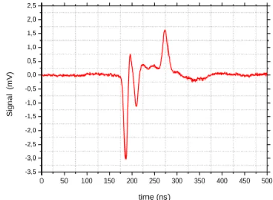
Fig. 7: PEA calibration signal for PI/PTFE bilayer sample with a total thickness of 130 µm.
Figure 7 shows a PEA signal for a PTFE/PI bilayer sample with a total thickness of 130 µm unload. For this measurement we apply to the sample a 1700V DC voltage and a 500V pulse voltage with a repetition rate of 5 kHz. Three peaks are observed in the PEA signal. Two peaks (175ns, 275ns) are related to the capacitive charges at the sample surfaces. The third peak located around 215ns is related to charges at the interface between the two layers. The charges at the interface can be due to the Maxwell-Wagner effect described above but the duration of polarization voltage application is too short to create these charges. We consider that these charges are present at the surface of one of the two layers and are trapped when the bilayer sample is realized. As a result, the interface charges change the distribution of the electric field in both layers.
Conclusions
In this paper, the rationale for developing space charge measurements on aeronautic cable has been highlighted. The accumulation of space charge results in the appearance of a residual electric field thus modifying the electrical stress on the insulator. Also the need for measuring directly electric field profiles in complex structures becomes evident when switching to dc networks. To evaluate the impact of this phenomenon, several space charge measurement methods have been developed over the last 40 years. They are distinguished mainly in two categories, thermal methods and acoustic methods. The selected method for space charge measurement on aeronautic cables is the pulsed electro-acoustic method. Advances with the development of the test bench will be presented at the conference.
References
1 B. Cella, T. Lebey, C. Abadie «Partial discharges measurements at the constituent’s level of aerospace power electronics converters», Proc. IEEE Electrical Insulation Conference (EIC), 2015, pp. 274-277. 2 C. Laurent, «Diélectriques solides et charge d’espace», Techniques de l’Ingénieur, 1999.
0 50 100 150 200 250 300 350 400 450 500 -1,75 -1,50 -1,25 -1,00 -0,75 -0,50 -0,25 0,00 0,25 0,50 0,75 Si gnal (mV) time (ns) 0 50 100 150 200 250 300 350 400 450 500 -3,5 -3,0 -2,5 -2,0 -1,5 -1,0 -0,5 0,0 0,5 1,0 1,5 2,0 2,5 Si g n a l (mV) time (ns)
3 B. Vissouvanadin, T.T.N. Vu, L. Berquez, G. Teyssedre, S. Le Roy, C. Laurent «Deconvolution techniques for space charge recovery using pulsed electroacoustic method in coaxial geometry», IEEE Trans. Dielectr. Electr. Insul. 2014, Vol. 21, pp. 821-828.
4 T.T.N. Vu, G. Teyssedre, B. Vissouvanadin, S. Le Roy, C. Laurent, «Correlating conductivity and space charge measurements in multi-dielectrics under various electrical and thermal stresses», IEEE Trans. Dielectr. Electr. Insul. 2015, Vol. 22, pp. 117-127 5 T. Mizutani, «Space charge measurement techniques and space charge in Polyethylene», IEEE Trans. Dielectr. Electr. Insul. 1994, Vol. 5, pp. 923-933.
6 S. Holé, T. Ditchi, J. Lewiner.«Non-destructive Methods for Space Charge Distribution Measurements: What are the Differences? » IEEE Trans. Dielectr. Electr. Insul. 2003, Vol. 10, pp. 670-677.
7 A. Toureille, P. Nothinger, J. Castellon, S. Agnel, «Les charges d’espace : définition, historique, mesure» dans Matériaux diélectriques pour le Génie Electrique, Lavoisier (Paris) 2007, Vol. 1, pp. 151-164.
8 M. Yasuda, M. Ito, T. Takada, «Measurement of charge distributions in coaxial cable using the pulsed electroacoustic method», Jpn. J. Appl. Phys., 1991, Vol. 30, pp. 71–73.
9 N. Hozumi, T. Okamoto, T. Imajo, «Space charge distribution measurement in a long size XLPE cable using the pulsed electroacoustic method», Conf. Rec. IEEE Int. Symp. Electr. Insul. (ISEIM), 1992, pp. 294– 297.
10 R. Bodega,J.J. Smit «Space charge measurements on multi-delectrictrics by means of the Pulsed Electro Acoustic method», IEEE Trans. Dielectr. Electr. Insul., Vol.13, No.2, pp 272-281, 2006.
11 T. Ditchi, C. Alquié, J. Lewiner «Broadband determination of ultrasonic attenuation and phase velocity in insulating materials», », J.Acoust. Soc. Amer., Vol. 94, No.6, pp. 3061-3065, 1993.