Publisher’s version / Version de l'éditeur:
Canadian Geotechnical Journal, 16, 1, pp. 11-18, 1979-02
READ THESE TERMS AND CONDITIONS CAREFULLY BEFORE USING THIS WEBSITE. https://nrc-publications.canada.ca/eng/copyright
Vous avez des questions? Nous pouvons vous aider. Pour communiquer directement avec un auteur, consultez la première page de la revue dans laquelle son article a été publié afin de trouver ses coordonnées. Si vous n’arrivez pas à les repérer, communiquez avec nous à [email protected].
Questions? Contact the NRC Publications Archive team at
[email protected]. If you wish to email the authors directly, please see the first page of the publication for their contact information.
NRC Publications Archive
Archives des publications du CNRC
This publication could be one of several versions: author’s original, accepted manuscript or the publisher’s version. / La version de cette publication peut être l’une des suivantes : la version prépublication de l’auteur, la version acceptée du manuscrit ou la version de l’éditeur.
Access and use of this website and the material on it are subject to the Terms and Conditions set forth at
Triaxial-vane tests on a soft marine clay
Law, K. T.
https://publications-cnrc.canada.ca/fra/droits
L’accès à ce site Web et l’utilisation de son contenu sont assujettis aux conditions présentées dans le site LISEZ CES CONDITIONS ATTENTIVEMENT AVANT D’UTILISER CE SITE WEB.
NRC Publications Record / Notice d'Archives des publications de CNRC:
https://nrc-publications.canada.ca/eng/view/object/?id=4f48c7c4-a7a0-46c3-9e6b-85cd6e62dcf1 https://publications-cnrc.canada.ca/fra/voir/objet/?id=4f48c7c4-a7a0-46c3-9e6b-85cd6e62dcf1
Nationa! Research
Conseil nationalI
*
Council Canada de recherches CanadaI
TRIAXIAL-VANE TESTS ON
A
SOFT MARINE CLAY
I I I by K. Tim s a w / j g q ~ ~ Y ZED Reprinted from
Canadian Geotechnical Journal
Vol. 1 6, No. 1, February 1 979
p. 11-1 8 I
DBR Paper No. 83 1
Division of Building Research
This publication is being distributed by the Division of Building Research of the National Research Council of Canada. It should not be reproduced in whole or in part without permission of the original publisher. The Division would be glad to be of assistance in obtaining such permission.
Publications of the Divisign may be obtained by mailing the
appropriate remittance (a Bank, Express, gr Post Office Money
Order, or a cheque, made payable to the Receiver General of
Canada, credit NRC) to the National Research Council of
Canada, Ottawa KIA 0R6. Stamps are not acceptable.
A list of all publications of the Division is available and may be
obtained from the Publications Section, Division of Building Research, National Research Council of Canada, Ottawa
Triaxial-vane tests on a soft marine clay
K. TIM LAW
Geotechnical Section, Division of Building Research, National Research Council o f Canada, Ottawa, Onr., Canada K I A OR6
Received April 19, 1978 Accepted September 6, 1978
This paper describes a triaxial-vane apparatus constructed at the Division of Building Re- search, National Research Council of Canada, Ottawa. A series of tests was conducted on a soft marine clay from South Gloucester, Ontario. Various consolidation pressures were used to study the effect of pressure on vane strength. The test results show that the vane strength is relatively insensitive to a change in vertical consolidation pressure only, but increases steadily with increase in the all-around or horizontal consolidation pressure. This phenomenon is explained using an analysis that incorporates strength anisotropy. The practical implications resulting from this study are also discussed.
I
On presente la description d'un appareil scissomCtrique en triaxial construit par la Division de recherches en bltiment du Conseil national de recherches du Canada, Ottawa. Une s6ie d'essais a CtC rCalisCe sur une argile marine molle de Gloucester sud, Ontario. Des pressions de consolidation variables ont CtC utilisks pour Ctudier l'effet des contraintes sur la resistance mesurk au scissomktre. Les rCsultats d'essais montrent que la rCsistance mesufk au scisso- mktre est relativement peu sensible aux changements de la pression de consolidation verticale seule, mais qu'elle augmente de f a ~ o n continue avec une augmentation de la pression de con- solidation isotrope ou horizontale. Ce phCnomkne est expliquC au moyen d'une analyse pre- nant en compte l'anisotropie de rksistance. Les implications pratiques de cette Ctude sont Cgalement c o m m e n t ~ s .
[Traduit par la revue]
Can. Geotech. J., 16. 11-18 (1979)
Introduction compression did show an increase. A possible ex-
The use of the vane shear test is in a state of un- planation of this apparent anomaly is that the vane certainty.
since
its introduction in its modern form strength is dependent on the horizontal stresses. by Cadling and Odenstad (1950), the vane shear test In provide a better understanding of the has been extensively used by engineers to obtain a vane shear test, the test should be conducted in ameasurement of the in situ undrained shear strength with drainage. An
in soft clays. Early experiences with this test showed apparatus was that made this possible that it was economical, easy to perform, and gave by combining the triaxial cell and the laboratory vane good assessment of the shear strength as back-cal- shear machine. This paper describes the apparatus culated from landslides (cadling and Odenstad 1950; in detail, gives the analysis of the test results, reviews ~d~~ and ~ ~19~7). Recent publications ~ i l some case histories, and discusses the practical ~ ~ ~ (Eide and Holmberg 1972; Dascal et crl. 1972) imp1ications.
showed, however, that it unacceptably overestimated
the shear strength in highly plastic clays. In an effort Description of Apparatus
to resolve this problem, Bjerrum (1972) compiled a The apparatus consists of a triaxial cell combined number of embankment failures from which a cor- with a Wykeham Farrance laboratory vane machine. rection curve relating the vane strength to the The complete setup is shown in Figs. 1 and 2. plasticity index was established. This approach, The rod (item 1 in Fig. 2) which transmits the however, has been strongly criticized by Schmert- torque from the vane machine to the vane (10) mann (1975), and more recent case records (Dascal passes through the centre of the triaxial piston (3). and Tournier 1975) demonstrated that the correction There are two couplings on the rod. The details of curve needed modification. the first coupling (8) are shown in Fig. 3. It consists In a previous field investigation (Law et al. 1977), of a hollow end with an inverted L-shaped slot on it was found that the vane strength of clays under the rod and a locking insert fixed on the top of the fills was essentially the same before and after appre- vane. With this coupling,'the vane is locked to the ciable compression. Strengths determined from rod when the latter is turned in a clockwise direction. piston samples from the same sites before and after A measurement is thus made of the total torque that
0008-3674/79/010011-08$01.00/0
12 CAN. GEOTECH. J. VOL. 16, 1979
T O V A N E
l d
FIG. 1. The triaxial-vane apparatus. 1 R O D 9 BAL SEAL 2 BAL SEAL 10 V A N E I P I S T O N I 1 DETACHABLE P I N 1 H A N G E R SYSTEM I ? H O U S I N G F O R V A N E
3 R O T A T I N G B U S H I N G 13 H Y P O D E R M I C T U B I N G overcomes soil strength around the vane and friction
on the rod, which is due to the soil and the BAL- seals1 (2, 9). As soon as the maximum torque is reached, the vane is released by turning the rod in the reverse direction. Hence, the portion of the torque caused by the friction from the soil and the seals can be measured. Subtracting this from the maximum torque obtained in the first stage gives the torque contributed by the resistance of the soil around the vane. This procedure of eliminating the friction component is different from that of Kenney and Landva (1965) and is believed to be more efficient.
A second coupling (7) is introduced to facilitate the mounting of the soil specimen. It is threaded, permitting the specimen and the cap (6) housing the vane to be mounted in a manner similar to that of an ordinary triaxial test. The piston, with the rest of the rod, is then lowered from the top through the rotating bushing (5). To tighten the coupling, a twist at the top of the rod is applied against the housing in the cap, which is prevented from turning by detachable pins (11) resting against two vertical posts (14) fixed to the collar (15) at the base (16).
The rod is turned by a small electric motor which is controlled by a reversing switch. By changing the
1973. BAL-seal Eng. Co., Justin, CA 92680, U.S.A.
4 C A P 14 P O S T 7 THREADED C O U P L I N G I 5 C O L L A R 0 S P E C I A L C O U P L I N G 16 BASE
FIG. 2. Details of the triaxial apparatus.
motor, a variety of strain rates can be applied. For the current series of tests the angular speed was set at SO/min.
The vane is similar geometrically to the Norwegian Geotechnical Institute (NGI) field vane which has been extensively used for the past 20 years by the Division of Building Research of the National Re- search Council of Canada. The area ratio of the blades and the central core to that of the circle cir- cumscribed by the vane is about 10%. The blades are made from 0.28 mm nichrome, 20 mm high and 10 mm in diameter, and can measure strength up to 100 kPa. In its retracted position, the vane is stored in a special housing (12) in the loading cap. At the bottom of the housing, there is a small recess upon which the vane rests during the mounting of the soil specimen.
Anisotropic consolidation can be applied to the soil specimen. This is achieved by putting an appro- priate load on the hanger (4).
Just before inserting the vane into the specimen in an undrained test, the back pressure valve at the base is closed while that of the cap is opened. Thus, volume compensation of the vane and the rod can be
LAW
l N V E R T E D L - S L O T
FIG. 3. Details of the coupling between the rod and the vane. provided through the stainless steel hypodermic tubing (13). When the vane is pushed to the middle of the specimen, the cap valve is closed and a vane shear test can then be conducted.
The original torque measuring device using spiral springs from the Wykeham Farrance vane machine is retained in the present system. Four springs of different stiffnesses are available for soils of varying strengths. With the present vane for use in a soft soil, a precision of 0.5y0 of the maximum torque can be achieved.
Testing Programme and Results
The soil specimens tested were obtained from the test site in South Gloucester, 21 km southeast of Ottawa, Ont., (from depths between 3.0 and 5.3 m) using the Osterberg 127 mm diameter sampler (Osterberg 1952). The soil is soft Leda clay, the characteristics of which have been studied in a re- search programme involving a test embankment con- structed at the site (Bozozuk and Leonards 1972). Briefly, it is a soft sensitive grey silty marine deposit, lightly overconsolidated, with a plastic limit of 24%, liquid limit of 48%, and natural moisture content of 70%.
Three series of triaxial-vane tests were conducted to study the change of strength under the following conditions: (a) a change of all-around consolidation
pressures 0,'; (b) a change of horizontal consolida-
tion pressure tsh' only; (c) a change of vertical con-
solidation pressure o,' only. These consolidation pressures included those that existed before and after
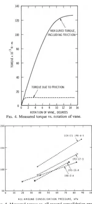
ROTATION OF VANE, DEGREES FIG. 4. Measured torque vs. rotation of vane.
S E R I E S 1 9 8 - 4 - 5
A L L - A R O U N D C O N S O L I D A T I O N P R E S S U R E , k P a
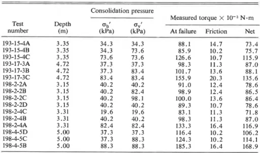
FIG. 5. Measured torque vs. all-around consolidation pres- sure.
the construction of the test embankment. The hori- zontal components of these stress states were mea- sured by Bozozuk (1974) using the hydraulic fracture technique.
In order to minimize sample variability, four 36.5 mm diameter specimens, 80 mm high, were trimmed from a single section of the Osterberg sample.
The results of all the tests are summarized in Table 1 and Figs. 4-7. Figure 4 shows the typical development of applied torque and of friction torque on the rod versus rotation'of the vane. The nonlinear torque-rotation relationship favours the use of a parabolic end shear distribution in the interpretation
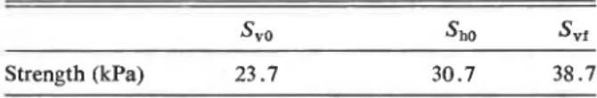
14 CAN. GEOTECH. J. VOL. 16, 1979 TABLE 1. Results of the triaxial-vane tests
- ~
Consolidation pressure
Measured torque X N - m Test Depth o h ' 0"'
number (m) (kPa) (kPa) At failure Friction Net
for strength over the other two more common assumptions, the uniform and the triangular end shear distributions, although the difference in results when using any one of them is generally unimportant. The friction torque as measured averages about 12% of the total torque.
The relationship between the net torque and the all-around consolidation pressure is shown in Fig. 5. The consolidation pressure o,' ranges from below the in situ effective horizontal pressure oho' to beyond the final vertical effective pressure o,f' under the test embankment. There is a steady increase of torque with consolidation pressure throughout this pressure range. From oho' to o,f', for instance, an average increase of torque of about 50% is measured.
Figure 6 shows a similar relationship between
torque and horizontal consolidation pressure at constant vertical pressure equal to o,f'. Within the same pressure range, the increase of torque is again about 50%.
A significantly different result is shown in Fig. 7 in which the torque is plotted against the vertical consolidation pressure o,' a t constant horizontal consolidation pressure equal to oho' In contrast to
the previous two series, the torque changes only a small amount with 0,'. The increase of torque within the same pressure range is only about 5%.
If the conventional strength isotropy is assumed in interpreting the results, the deduced or apparent vane strength will be directly proportional to the torque. This would then lead to the conclusion that within the tested pressure range, the apparent vane
1 5 0 1 1 I 1 I r l I SER I E S l ? B - U - J
-
_
--
---.
1 0 0-
I Q I - 1 7 - 3 - 4--- 5 0 + I P S - 2 - 2-
H O R I Z O N T A L C O N S O L I D A T I O N P R E S S U R E . k P a V E R T I C A L C O N S O L I D A T I O N P R E S S U R E , k P aFIG. 6. Measured torque vs. horizontal consolidation pres- FIG. 7. Measured torque vs. vertical consolidation pressure sure at constant vertical consolidation pressure. at constant horizontal pressure.
LAW
TABLE 2. Definition of strengths and torques Consolidation pressure Symbols of shear strength Test Vertical Horizontal On vertical On horizontal
type direction direction plane plane Maximum torque
N m : ubo' and u,.r' are the in siru effective horizontal pressure and final effective vertical pressure under the fill.
respectivelv.
strength is relatively insensitive to an increase in the vertical consolidation pressure only, but is sensitive and increases steadily with an increase in the all- around or the horizontal pressure. A more accurate interpretation is presented in the next section.
Analysis of Test Results
The interpretation of test results is based on the usual assumption that the soil fails along the ends and side of the cylinder circumscribed by the vane. Because a highly complex stress field is induced as a result of the insertion and turning of the vane, the strength referred to hereafter should only be regarded as a measure of the maximum soil resistance on the cylindrical surface under the prevailing stress system. A list of symbols used in this analysis is defined in Table 2.
Strength anisotropy is included in the interpreta- tion. Therefore, the strengths on the vertical and horizontal surfaces, S , and Sh respectively, may be different. They can be related to the maximum torque (T), assuming a parabolic end shear distribu- tion,
where H a n d D are height and diameter of the vane, respectively.
In order to determine the strengths on the two surfaces at various pressures, some of the known behaviour of this material must be noted. Mitchell (1970) shows that strength anisotropy for a Leda clay from Ottawa prevails at low stress range and that it vanishes beyond the preconsolidation pressure PC. Assuming this is also true in the present case, we obtain
S,f = Shf (for ovf'
>
pc)With the average values from each test series, the various strengths were calculated and are shown in Table 3. A comparison of Tables 2 and 3 shows that there is a definite strength increase on the horizontal plane with increase in the vertical consolidation pressure s,'. This strength increase, however, is associated with a smaller area and a shorter moment arm on the end planes of the cylindrical failure surface. It does not, therefore, contribute significantly to the total torque. Thus, the torque measured and the deduced apparent vane strength based on isotropy are not very sensitive to changes in o,', as has been noted in the previous section.
After determining the various strength values, the rate of change in strength with respect to normal pressure on the vertical and the horizontal planes can be evaluated as ASv/Asht = 0.33 and ASh/AoVt
= 0.18. These values are markedly different from
each other. The lower rate of strength increase on the horizontal plane probably stems from a higher preconsolidation pressure on this plane. Based on this rate and taking KO = 0.8 (Bozozuk 1974), the ratio of the vane strength on the horizontal plane to that on the vertical plane is found to be 1.36 under the in situ state of stress.
Case Records
Field vane shear tests were conducted in the sub- soils of four fills, including the one at South Glouces- ter (Law et al. 1977). The apparent vane strengths were found to be practically the same as those before the embankments were placed. The effective hori-
TABLE 3. Results of calculating strengths on different planes at different stresses
By defining a = (10H
+
3D)/10D it can then beshown (Appendix) that SVO S h ~ Sv f
CAN. GEOTECH. I. VOL. 16, 1979
T V E R T I C A L P R E S S U R E I 1As,l Practical Implications
1
/-
P O R E W A l C R P R E S S U R E ( A u l---
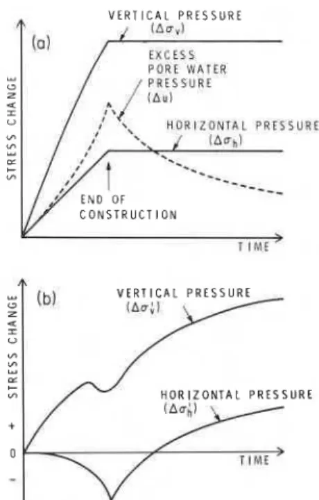
C O N S T R U C T I O N H O R I Z O N T A L P R E S S U R EFIG. 8. Illustration for pressure changes in the subsoil under a fill during and after consolidation: ( a ) change of total and porewater pressures; (b) change of effective pressures.
zontal stresses in these cases were estimated using finite element analysis or the hydraulic fracture technique (Bozozuk 1974). No significant increase in horizontal pressure due to the embankments was indicated. The apparent lack of vane strength in- crease can therefore be correlated to the insignificant horizontal pressure increase. On the other hand, other field evidence and triaxial tests on soils that failed on a plane at about 56" from the horizontal showed that there was a definite strength increase. These observations are in agreement with the analysis of the triaxial-vane test results presented in the foregoing section.
A question may arise as to the applicability of data from axisymmetric tests to the plane strain condition. The difference lies in the change in the intermediate principal stress, a quantity related to the drained Poisson's ratio. Triaxial tests in the appropriate stress range were conducted on the South Gloucester soil. The drained Poisson's ratio was found to be less than 0.1 and the resulting strength gain due to the plane strain condition was less than 3%. This is beyond the precision of the NGI field vane shear test. The laboratory data are therefore applicable to the field situation in this particular case. The soils under the other three fills behaved similarly and it is likely that the same conclusion can be drawn.
case.
Summary and Conclusion
One important implication of this study is that the apparent vane strength obtained from the conven- tional vane shear test does not reliably reflect strength gains under loading. This apparent vane strength strongly depends on the effective horizontal pressure, which is in turn influenced by a large
number of factors related to the soil compressibility I and the boundary conditions (Law and Lo 1976).
It is then possible that the apparent vane strength may remain practically constant in spite of a definite strength increase on planes other than the vertical. This view is demonstrated by the present test series and by the work of Law et al. (1977), which com- pared increases in the apparent vane and triaxial strengths.
A second implication is that the apparent vane strength may decrease after a structure is built. Consider the stresses generated in the subsoil under
A triaxial-vane apparatus was constructed and used successfully at the Division of Building Re- search of the National Research Council of Canada. Special couplings were devised to provide sealing and to separate the friction component from the mea- sured torque, thus permitting an evaluation of the apparent vane strength of the soil. Tests were a fill during and after its construction (Fig. 8). Steady increases in total pressures, both vertical and horizontal (AD,, Aoh), are induced during the con- struction stage; the excess porewater pressure (Au) also increases as shown in Fig. 8a. After the con- struction stops, Au begins to dissipate while, for the sake of simplicity and not of necessity, A o v and Aoh remain constant. The changes in effective vertical and horizontal pressures (Ao,', Aoh') can be calcu- lated and are shown in Fig. 8b. Ao,' is positive at all times, whereas A o h ' is negative until Au has dissi- pated to the condition that Au
5
Aob. Before this condition is reached, there is a reduction in effective horizontal pressure. A vane test conducted within this period may therefore register a strength reduc- tion. Such an observation has been reported by Stermac et al. (1967).The difference in the rates of strength increase on different planes as shown earlier will introduce additional strength anisotropy in this lightly over- consolidated soil during loading. It implies that in stage construction on this soil, undrained stability analysis in the second stage should be performed with caution. A single rate of strength increase as used by Ladd and Foott (1974) is not suitable in this
carried out on specimens from a soft marine deposit near Ottawa. The results show that the apparent vane strength interpreted using strength isotropy is relatively insensitive to a change in vertical consoli- dation pressure under constant horizontal consolida- tion pressure, but increases steadily with increase in the all-around or the horizontal consolidation pres-
.
sure.An analysis of the results incorporating strength
I anisotropy indicates a definite strength increase with
normal pressure on either the horizontal or the vertical plane. The rate of strength increase on the horizontal plane is significantly smaller than that on
1
the vertical plane, yet both rates are appreciablygreater than zero. Such strength increases not re- flected in the apparent vane strength under a pressure increment solely in the vertical direction are due to the combined effect of the smaller rate of strength increase on the horizontal plane, shorter moment arm, and smaller area on the end failure plane.
Case histories involving similar materials have been reviewed and were found to give results con- sistent with those from the laboratory tests. It is therefore concluded that the apparent vane strength obtained from the vane shear test is not a good indicator of strength gain under sustained loading.
I
AcknowledgementsThe design of the triaxial-vane apparatus is the result of a series of discussions with the staff of the Geotechnical Section and the workshop in the Division of Building Research of the National Re- search Council of Canada. J. B. Bordeleau, technical officer of the Geotechnical Section, carried out a large portion of the tests.
This paper is a contribution from the Division of Building Research, National Research Council of
I Canada, and is published with the approval of the
i
director of the division.BJERRUM, L. 1972. Embankments on soft ground. State-of-
the-art report. Proceedings, ASCE Specialty Conference on Performance of Earth and Earth-supported Structures, Lafayette, IN, Vol. 11, pp. 1-54.
B o z o z u ~ , M. 1974. Minor principal stress measurements in
marine clay with hydraulic fracture tests. Proceedings, ASCE Specialty Conference on Subsurface Exploration for Under- ground Excavation and Heavy Construction, Henniker, NH, pp. 333-349.
B o z o z u ~ , M., and Leonards, G.A. 1972. The Gloucester test
fill. Proceedings, ASCE Specialty Conference on Perform- ance of Earth and Earth-supported Structures, Lafayette, IN, Vol. 11, pp. 299-317
CADLING, L., and ODENSTAD, S. 1950. The vane borer. Pro-
ceedings No. 2, Royal Swedish Geotechnical Institute, Stockholm, Sweden.
DASCAL, O., and TOURNIER :J. P. 1975. Embankments on soft
and sensitive clay foundation. ASCE Journal of the Geo- technical Engineering Division, 101(GT3), pp. 297-314.
DASCAL, O., TOURNIER, J. P., TAVENAS, F., and LA ROCHELLE,
P. 1972. Failure of a test embankment on sensitive clay. Proceedings, ASCE Specialty Conference on Performance of Earth and Earth-supported Structures, Lafayette, IN, Vol. I, Part 1, pp. 129-158.
EDEN, W. J., and HAMILTON, J. J. 1957. The use of a field vane
apparatus in sensitive clay. Symposium on Vane Shear Testing of Soils, American Society for Testing and Materials, Special Technical Publication No. 193, pp. 41-53.
EIDE, O., and HOLMBERG, S. 1972. Test fills to failure on the
soft Bangkok clay. Proceedings, ASCE Specialty Con- ference on Performance of Earth and Earth-supported Structures, Lafayette, IN, Vol. I, Part 1, pp. 159-180.
KENNEY, T. C., and LANDVA, A. 1965. Vane-triaxial apparatus.
Proceedings, 6th International Conference on Soil Mechan- ics and Foundation Engineering, Montreal, P.Q., Vol. I, pp. 269-272.
LADD, C. C., and Foorr, R. 1974. New design procedure for stability of soft clays. ASCE Journal of the Geotechnical Engineering Division, 100(GT7), pp. 763-786.
LAW, K. T., and Lo, K. Y. 1976. Analysis of shear-induced
anisotropy in Leda clay. Proceedings, 2nd International Conference on Numerical Methods in Geomechanics, Blacksburg, VA, Vol. 1, pp. 329-344.
LAW, K. T., BOZOZUK, M., and EDEN, W. J. 1977. Measured
strengths under fills on sensitive clay. Proceedings, 9th International Conference on Soil Mechanics and Founda- tion Engineering, Tokyo, Japan, Vol. 1, pp. 187-192.
MITCHELL, R. J. 1970. On the yielding and mechanical strength
of Leda clays. Canadian Geotechnical Journal, 7(3), pp. 297-312.
OSTERBERG, J. 0. 1952. New piston tube sampler. Engineering
News-Record, 148, pp. 77-78.
SCHMERTMANN, J. H. 1975. Measurement of in situ shear
strength. Proceedings, ASCE Specialty Conference on In
situ Measurement of Soil Properties, Raleigh, NC, Vol.
11, pp. 57-138.
STERMAC, A. G., LO, K. Y., and BARSEVARY, A. K. 1967. The
performance of an embankment on a deep deposit of varved clay. Canadian Geotechnical Journal, 4(1), pp. 45-67.
Notation
D,
H = diameter and height of the vanerespectively
K O
= coefficient of earth pressure at restSh,
SV
= vane strengths on the horizontal andthe vertical planes respectively
she, SVO = vane strengths on the horizontal and
the vertical planes under an all- around consolidation pressure equal
to the in situ effective horizontal pres-
sure, respectively
Svr S h f = vane strengths on the horizontal and
the vertical planes under an all- around consolidation pressure equal to the effective vertical pressure under the test embankment, respectively
T = torque
18 CAN. GEOTECH. J. VOL. 16, 1979
ccl, c h t , evt = the all-around, horizontal, and verti- Solving the four equations simultaneously one
cal consolidation pressures, respect- obtains
ively 2(Tb
-
3Tc/10a)= in situ effective horizontal pressure s v o =
c h o l (a
-
3/10)7cD3 . -evf ' = vertical effective pressure under the
test embankment S h o = ---;.[lo(Ta 2 - Tb)/3
+
Tc/a]A = a change. 7cD
Appendix
Derivation of Svo, S ~ O , and Svf
Based on [l] and using symbols in Table 2, one can write [A31 Tc =
-
S v r+
- S h f 2 =D3( IOH 3D1
Now from [2]fA41
Svf = S h f where a = (10H+
3D)/10DThe above derivation uses an assumption that
needs some clarification. It is assumed that Svo re-
mains unchanged in cases 1 and 2 in Table 2. This is
based on the fact that in both cases the normal (horizontal) effective pressures are equal before shearing. Once shearing begins, however, porewater pressures generated in each case will lead to different effective pressures at failure. This aspect was ex- amined during the experiment by measuring the excess porewater pressure. Using the rate of strength increase on the vertical plane, the resulting change in
Svo due to the slightly different effective pressure at
failure was found to be insignificant. The assumption is therefore acceptable.
A similar procedure was also applied in the case of