Performance Analysis for an IP Differentiated Services Network
C Chassot
1, F Garcia
1, G Auriol
1, A Lozes
1, E Lochin
2, P Anelli
21
LAAS/CNRS, 7 avenue du Colonel Roche, 31077 Toulouse cedex 04, France email: chassot, fgarcia, gauriol, [email protected]
2
LIP6, 8 rue du Capitaine Scott, 75015 Paris, France email: emmanuel.lochin, [email protected]
Abstract-Research reported here deals with a communication architecture with guaranteed end-to-end quality of service (QoS) in an IPv6 environment providing differentiated services within a single DiffServ domain. The article successively presents the design principles and services of the proposed architecture, their implementation over a national platform, and experimental measurements evaluating the QoS provided at the user level.
I.
I
NTRODUCTIONTechnical revolutions in computer science and telecommunications have led to the development of several new types of distributed applications such as multimedia and co-operative applications or interactive simulation. These new applications present challenging characteristics and constraints to network designers, such as higher bandwidths, the need for bounded delays, etc. Quality of Service (QoS) describes the assurance of data transfer that fits to the application requirements. This area has been one of the principal topics of research and development in data networks for many years. In the Internet community, two research and development efforts (IETF1IntServ [1] and DiffServ [2] working groups) have been carried out in order to develop a QoS framework for the TCP/IP protocol suite. Several research projects have been initiated to target the QoS problem within the Internet. Among them, let’s cite the TF-TANT activity [3] and the GEANT, TEQUILA, CADENUS, AQUILA and GCAP IST projects [4, 5, 6, 7, 8], all of them implementing a differentiated services QoS architecture.
Performed within the national French project @IRS2, work presented here follows the mains DiffServ principles. More precisely, it deals with the conception, the implementation and the evaluation of a communication architecture providing a guaranteed end-to-end QoS in an IPv6 environment constituting a single DiffServ domain. This work provides the following contributions:
− it proposes an architecture with well-defined services;
− it validates the decomposition of the service model by an implementation of the architecture over a national ATM research infrastructure named RENATER2;
− it evaluates and analyses the QoS provided at the user level by mean of experimental measurements.
This article is structured as follows. Section II presents the architecture principles and services, and then describes the experimental platform over which the architecture has been developed. Section III details the experimental scenarios for the study of the end to end QoS; results of the experimental measurements are also provided and analyzed. Conclusions and future works are presented in Section IV. Note that a part of this work is presented in [9]. Contributions presented here essentially differ from those of [9] on the third part, dedicated to the experimental measurements.
1
IETF: Internet Engineering Task Force
2@IRS project (Integrated Networks and Services Architecture - Dec. 1998-April
2001) is a national project of the France's Réseau National de la Recherche en
Télécommunications, whose objective was to experiment innovative Internet
mechanisms within an heterogeneous network infrastructure (ATM, LAN, etc.).
II.
A
RCHITECTUREP
RINCIPLES,S
ERVICESA
NDI
MPLEMENTATIONThe following two major sections (A and B) successively present the architecture defined at the end-to-end level and at the network level. A. End-to-end level
The basic underlying principle that supports the proposal of the @IRS end-to-end architecture is one of many dedicated to the transport of multimedia flows [10, 11,12]. The idea is that the traffic exchanged within a distributed application can be decomposed into several data flows each one requiring its own specific QoS (delay, reliability, order, etc.). That is, an application can request a specific QoS for each of its flow via a consistent API (Application Programming Interface) offering parameters and primitives for access to the communication service.
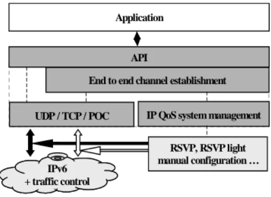
By way of a session (see Fig. 1), the application layer software is then allowed to establish one or many end-to-end communication channels, each being: unicast or multicast, dedicated to the transfer of a single flow of application data, and able to offer a specific QoS.
IPv6 + traffic control
..
Application
UDP / TCP / POC
End to end channel establishment
IP QoS system management API
RSVP, RSVP light manual configuration …
Fig. 1. Architecture of the end-to-end com. system Besides the API, three other modules are defined:
− the first one provides multiple transport layer possibilities, such as TCP, UDP, or the partial-order/reliable POC protocol [13, 14]; − the second one implements the mechanisms linked to the utilization of QoS services at the IP layer (RSVP, RSVP light, etc.);
− the third one is in charge of the end-to-end channel set up.
Due to space limits, we only present the service parameters of the API. For each channel, QoS is expressed by the following parameters:
− a partial order3, expressed as both an intra and an inter flow order, since a user may want a logical synchronization service either within each flow (e.g., logical synchronization of two media transported within the same end-to-end channel), or between flows (e.g., logical synchronization of voice and video);
3The goal of this paper is not to describe and enforce ordering relationships within
channels that may lose packets to tackle synchronization needs or to reduce data transit delay. Identically, Usefulness of RTP based propositions is not studied.
− a partial reliability defined, for example, by a maximum number of consecutive lost packets, and/or a maximum % of lost packets; − a maximum end-to-end transit delay.
In addition, an application must specify four service parameters: − the first one characterizes the traffic generated by the application sender (here, a token bucket);
− the second one designates which transport protocol to use (e.g. UDP, TCP or POC);
− the third one designates the IP layer's QoS management desired by the application (e.g. IntServ Guaranteed or Controlled Load services, DiffServ Premium or Assured services, etc.);
− the final parameter identifies the address, either unicast or multicast, of a set of destination application software’s.
Although the architecture is designed so as to allow several Transport protocols or IP level management systems, the one implemented within the project only includes UDP and TCP at the transport level and a DiffServ proposition (described hereafter) at the IP level.
B. Network level
QoS management functions performed at the network level can be divided in two parts: those related to the data path and those related to the
control path. On the data path, QoS functions are applied by routers in order
to provide different levels of service. On the control path, QoS functions concern routers configuration so as to enforce the QoS provided. If studies performed during the @IRS project tackle the two areas (data and control paths), only the data part has been implemented and evaluated over the experimental platform. In this section, we first describe the defined services at the IP level. Then we detail the different functions required for the services implementation.
1)Services. Three services have been defined at the IP level:
− GS (Guaranteed Service) analogous to the Premium Service [15] -is used for data flows having strong constraints both in terms of delay and reliability. Applications targeted by GS are those which do not tolerate QoS variation;
− AS (Assured Service) is appropriate for responsive flows having no strong constraints in terms of delay, but requiring a minimum average bandwidth. More precisely, a flow served in AS has to be provided with an assured bandwidth for the part of its traffic (IN packets) respecting the characterization profile specified for the flow. Part of the traffic exceeding the characterization (OUT or opportunistic -packets) is conveyed in AS as far as no congestion occurs in the network on the path used by the flow;
− BE: Best Effort service offers no QoS guarantees.
Three markings have been defined to differentiate packets: EF (Expedited Forwarding) [16], AF (Assured Forwarding) [17] and DE (Discard Eligibility), associated to the services provided at the IP level.
2)Control path QoS functions. In order to implement the IP level
services, mechanisms involved in the control path are admission control, route change protection and multicast management. Due to space limits, we only present admission control principles.
The admission control takes care of the acceptance of new flows in service classes. Its decisions are taken according to the TCA1contracted between the user domain and the service provider domain. Our proposition is different for AS and GS:
− for AS, a per flow admission control is applied at the edge of the network (core routers are not implied); this control is based on the 1TCA - Traffic Control Agreement: part of the Service Level Agreement [18] that
describes the amount of traffic a user can send to the service provider network.
amount of AS traffic already authorized to enter the network by the considered edge router. This gives the guarantee that at any time, the amount of in profile AS packets (IN packets) in the network will be at most the sum of the AS authorized at each edge router;
− for GS, as a delay guarantee is needed, the admission control involves all the routers on the data path. It is also applied per flow, each one being identified by the couple (flow_id field, source address).
3)Data path QoS functions. QoS functions involved in the data path
are policing, scheduling and congestion control. Data path functions description
Policing. Policing deals with the actions to be taken when out of profile
traffic arrives in a given service class:
− for AS, the action is to mark the out of profile packets with a higher drop precedence than for the IN traffic. OUT packets are called
opportunistic packets because they are processed like the other IN AS
packets, as far as no congestion occurs in the network. If congestion occurs, the congestion control described here after is applied. Targeted applications are those whose traffic is elastic, that is with a variable profile (a minimum still being assured);
− for GS, as a guarantee exists, it must be sure that enough resources are available; therefore the amount of GS traffic in the network must be strictly controlled. The chosen policing is to shape the traffic at the edge router and to drop out of profile GS packets.
Scheduling. Scheduling is different for AS and GS packets:
− GS scheduling is implemented by a Priority Queuing (PQ) mechanism. This choice is due to the fact that a PQ scheduler adds the smallest delay to the packet forwarding due to packetization effect; − the remaining bandwidth is shared by a Weighted Fair Queuing (WFQ) between AS and BE traffic.
Congestion control. The congestion control issue is essential for QoS
services, as a congestion can prevent the network from offering the contracted QoS to a flow:
− GS traffic does not need congestion control as it benefits from a priority queuing ensuring that all its packets are served up to the maximal capacity of a given router. Associated with a drop of out of profile packets at the network boundary, this guarantees that no congestion will occur in routers GS queues;
− for AS, as opportunistic traffic is authorized to be sent in the network, the amount of AS packets in any router can’t be known a priori. Therefore, a drop precedence system has been implemented; it allows the drop of opportunistic packets as soon as a congestion is about to occur in an AS queue. A Partial Buffer Sharing (PBS) has been chosen on AS queues rather than a Random Early Discard (RED) method in order to avoid queue length oscillation problems [19,20].
Let us now look at the implementation of these functions over the @IRS platform through the input interface of the first router (edge router) and the
output interface of all routers (edge and core routers).
Data path functions implementation
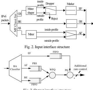
Input interface of edge router (see Fig. 2). This interface is the first
encountered by a packet when it enters the network. It is in charge of: − classifying packets, by means of source address and flow_id IPv6 header fields (Multi-Field Classification);
− measuring AS/GS flows to determine whether they are in profile; − shaping GS packets and dropping them if necessary;
− marking AS packets either IN or OUT;
− marking AS/GS packets with the appropriate DiffServ CodePoint; − marking BE packets to prevent them from entering the network with the DSCP of another service class.
Output interface of all routers. In the DiffServ model, all routers must
implement a set of forwarding behaviors called Per Hop Behavior (PHB). In the @IRS architecture, these behaviors are implemented through scheduling and AS congestion control. They are integrated in the output interface of each router (Fig. 3).
Two additional points must be noted: the Behavior Aggregate (BA)
Classifier which classifies packets according to their DSCP, and the rate
control at the output of core routers. As it will appear clearly in the next section, this control is necessary to avoid congestion at the ATM level.
IPv6 packets GS AS inside-profile outside-profile EF AF Reject Meter shaper Dropper MF C las si fi er Meter Marker inside-profile outside-profile DE BE
Fig. 2. Input interface structure
WFQ PQ BA Classifier EF AF BE FIFO PBS FIFO Additional rate control
Fig. 3. Output interface structure
III.
S
CENARIOSA
NDM
EASUREMENTSA first set of experimental measurements have been realized on the @IRS platform [9]. The major goal of those experiments was to evaluate the QoS provided to a single UDP flow served in AS (respectively in GS) in presence of a BE traffic whose load was progressively increased until complete overload of the network. Starting from those first results, the goal of the experiments presented in this section is threefold:
− study the QoS provided to several UDP flows served in AS (resp. in GS), generated without GS (resp. AS) traffic in the network, but in presence of a BE traffic overloading the network;
− study the QoS provided to one or several UDP flows served in AS, generated together with one or several flows served in GS, in presence of a BE traffic overloading the network;
− discuss the possibility to characterize an AS-like service for a given configuration of a DiffServ platform like the @IRS one.
We first present the @IRSbone configuration, then the experimental scenarios and finally the experimental results and their analysis.
A. @IRSbone configuration
Measurements have been realized between LAAS (Toulouse) and LIP6 (Paris) over the IPv6 environment illustrated on Fig. 4. It is part of the @IRSbone platform, including other French sites, not illustrated here.
Local platforms are connected by edge routers (Re) to an Internet
Service Provider (ISP) represented by the national ATM RENATER2
platform. Four core routers (Rc) are introduced within the ISP. Physically, they are located in the local platforms, but logically they are part of the ISP. By means of its edge router, each site is provided with an access point to the ISP, characterized by a statically established traffic contract called Service
Level Agreement (SLA) [20]. For each service, this SLA consists of:
− several classification and packet (re)marking rules;
− a sending traffic profile (the Traffic Conditioning Agreement -TCA [20]) : for @IRS, the model chosen is the Token Bucket;
− actions the network has to perform when TCA is not respected. It is the edge router’s responsibility to implement the SLA as it introduces application flows within the ISP. Bandwidth of the link connecting LAAS (resp. LIP6) to the ISP (via an ATM VP at 1Mbit/s CBR service) is such that the maximal throughput provided at the UDP level is 107 Kbytes/s with packet payload of 1024 bytes. In the following of the paper, we use the term link bandwidth to refer to this throughput.
Re X Rc RENATER2 LAAS-CNRS (Toulouse) Re X Rc LIP6 (Paris) BSDA BSDC ISP AS/GS/BE AS/GS/BE ATM switch ATM switch BSDB Ethernet 10 Mbits/s AS/GS/BE
Fig. 4. Network configuration
Edge and core routers are configured with the following hypothesis: − the maximal amount MAGSof GS traffic that can be generated by the edge router (in average) has been fixed to 20 Kbytes/s, i.e. about 20% of the link bandwidth;
− the maximal amount MAASof AS traffic that can be generated by the edge router (in average) has been fixed to 40 Kbytes/s, i.e. about 40% of the link bandwidth;
− the rate control applied by the core router is 100 Kbytes/s;
− weights associated to the AS and BE packet scheduling within the WFQ mechanism are respectively 0.5 and 0.5.
B. Experimental scenarios
Three scenarios have been designed:
− the first scenario is aimed at validating the impact of the number of AS flows on the AS QoS, when the network is overloaded. No GS flow is generated;
− the second scenario is aimed at validating the impact of the number of GS flows on the GS QoS, when the network is overloaded. No AS flow is generated;
− the third scenario is aimed at validating the impact of the number of AS (resp. GS) flows on the GS (resp. AS) QoS, when the network is overloaded. Here, AS and GS flows are generated together.
Measured parameters are the end to end transit delay and the loss rate: minimal, maximal and average values of the transit delay are calculated for experiment sessions (about 300 seconds for each one); distribution of the transit delay is also evaluated; the loss rate corresponds to the ratio {number of not received packets / number of sent packets} for a complete session.
1)Scenario 1 (resp. scen. 2). For those measurements (see Table 1):
− AS (resp. GS) flows are sent from PC BSDA and BSDB to PC BSDC. Three cases are considered:
• a single AS (resp. GS) flow is generated from PC BSDA with a mean rate corresponding to 50% of the maximal amount MAAS(resp. MAGS) allocated for AS (resp. GS) traffic;
• 2 distinct AS (resp. GS) flows are generated from PCs BSDAand BSDBwith a mean rateó 23 and 27% of MAAS(resp. MAGS);
• 4 distinct AS (resp. GS) flows are generated from PCs BSDAand BSDBwith a mean rateó 11, 12, 13 and 14% of MAAS(resp. MAGS);
− 2 BE flows are sent from PC BSDAand BSDB. Sum of their mean rate is 100 Kbytes/s, i.e. about the totality of the link bandwidth (LB).
Scenario 1 (scenario 2)
% of the allocated bandwidth
Throughput of the BE traffic (% of the link bandwidth - LB)
AS (BSDA) 50 100 (BSDB) AS1(BSDA) AS2(BSDB) 23 27 100 (50 % BSDA- 50 % BSDB) AS11(BSDA) AS12(BSDA) AS21(BSDB) AS22(BSDB) 11 12 13 14 100 (50 % BSDA- 50 % BSDB) Table 1. Traffic spec. for scen. 1 (replace AS with GS for scen. 2)
2)Scenario 3. For those measurements (see Table 2):
− AS (resp. GS) flows are sent from PC BSDA (resp. BSDB) to PC BSDC; two cases are considered:
• a single AS flow is generated from PC BSDA with a mean rate corresponding to 100% of the maximal amount allowed for AS. In parallel, a single GS flow is generated from PC BSDB; its mean rate corresponds to 100% of the maximal amount allowed for GS;
• 2 distinct AS flows are generated from PCs BSD A and B with a mean rate corresponding for each one to 50% of the maximal amount allowed for AS traffic. In parallel, two distinct GS flows are generated from PCs BSD A and B with a mean rate corresponding for each one to 50% of the maximal amount allowed for GS traffic;
− 2 BE flows are sent from PC BSDAand BSDB. Sum of their mean rates is 100 Kbytes/s, i.e. about the totality of LB.
Scenario 3 % of the allocated
bandwidth
Throughput of the BE traffic (% of the link bandwidth - LB) AS (BSDA) GS (BSDB) 100 100 100 (50 % BSDA- 50 % BSDB) AS1(BSDA) AS2(BSDB) GS1(BSDA) GS2(BSDB) 50 50 50 50 100 (50 % BSDA- 50 % BSDB) Table 2. Traffic specification for scenario 3
− all flows are generated by a software tool named Debit6 (developed by LIP6/LAAS), able to send UDP traffic respecting a token bucket type-like profile. Throughput and loss rate for a given session, and transit delay for each packet, are collected in reception by this tool; − all flows are generated by bursts of one 1024 bytes (1 Kbytes) length UDP packet. The inter-packet delay is the variable parameter used to change the throughput of the generated flows;
− AS and GS flows respect their traffic profile;
− hosts are synchronized by means of Network Time Protocol (NTP), inducing a +/- 5 ms uncertainty on the transit delay measurements. C. Results and analysis
Results are given by means of: (1) a figure representing on the y-axis the % of packets received with a transit delay less than or equal to the value denoted on the x-axis, and (2) a table indicating for each flow the loss rate and the {min, average. and max} values of the transit delay.
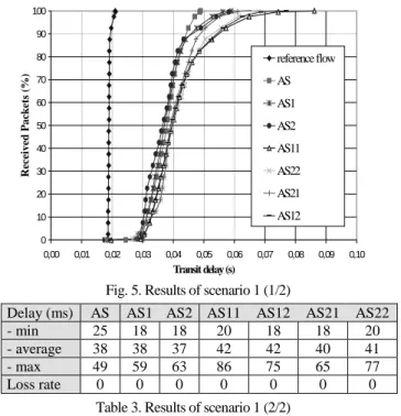
1)Scenario 1: {AS * 1, 2, 4 flows} vs. BE (100 % LB). As indicated on
Fig. 5 and Table 3, the impact of the number of AS flows on the AS QoS is weak. Indeed, Table 3 indicates that a variation smaller than 5 ms is observed for the average value of the transit delay. Fig. 5 enforces this result: for 90% of the packets, transit delay is almost unchanged. However, one can notice that 10% of the packets (for AS1, 2, 11, 12, 21, 22) have a transit delay much greater than for the one
observed for the single AS flow. Our first explanation was to associate this result to the asynchronism of the PCs OS (Free BSD). However, as this phenomenon does not appear for GS experiments (see results of scenario 2), this explanation seems not valid. At the present time, no valid explanation as been given. Loss rate is unchanged (no loss).
Note : on Fig. 5, the curve named reference flow is the one obtained for a single AS flow when the network is not overloaded with BE traffic.
0 10 20 30 40 50 60 70 80 90 100 0,00 0,01 0,02 0,03 0,04 0,05 0,06 0,07 0,08 0,09 0,10 Transit delay (s) R ecei ved P ack ets (% ) reference flow AS AS1 AS2 AS11 AS22 AS21 AS12
Fig. 5. Results of scenario 1 (1/2)
Delay (ms) AS AS1 AS2 AS11 AS12 AS21 AS22
- min 25 18 18 20 18 18 20
- average 38 38 37 42 42 40 41
- max 49 59 63 86 75 65 77
Loss rate 0 0 0 0 0 0 0
Table 3. Results of scenario 1 (2/2)
3) Scenario 2: {GS * 1, 2, 4 flows} vs. BE (100 % LB). As indicated on Fig.
6 and Table 4, the impact of the number of GS flows on the GS QoS is weak. Indeed, Table 4 indicates that a variation smaller than 8 ms is observed for the average value of the transit delay (for all packets). Fig. 6 enforces this result for all packets. Loss rate is unchanged (no loss).
0 10 20 30 40 50 60 70 80 90 100 0,00 0,01 0,02 0,03 0,04 0,05 Transit delay (s) Recei v ed P a ck et s (% ) GS11 GS21 GS22 GS12 GS GS1 GS2
Fig. 6. Results of scenario 2 (1/2)
Delay (ms) GS GS1 GS2 GS11 GS12 GS21 GS22
- min 19 16 16 18 18 18 18
- average 25 26 26 32 31 33 31
- max 33 33 35 33 34 37 38
Loss rate 0 0 0 0 0 0 0
Table 4. Results of scenario 2 (2/2)
Note that the 20 ms maximal difference that appears for the transit delay is acceptable. Indeed, keeping in mind that: (1) GS transit delay for a given
packet is expected to be the minimal one with a possible jitter equivalent to the presence of one buffered GS packet when the considered packet arrives in a router, (2) emission of a BE packet can’t be interrupted, and (3) all packets have a fixed 1 Kbytes length and are sent with a rate limited to 100 Kbytes/s, it results that a 20 ms additional delay appears in the worse case.
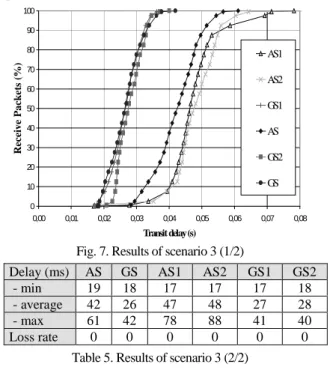
2)Scenario 3: {AS&GS * 1, 2 flows} vs. BE (100 % LB). As indicated
on Fig. 7 and Table 5, the impact of the number of GS flows on the AS QoS (and reciprocally) is almost null. Indeed, Table 5 indicates that a variation smaller than 6 ms for AS and 2 ms for GS for the average value of the transit delay (for all packets). This is confirmed by Fig. 7 for all packets. Once again, loss rate is unchanged (no loss).
Note that the transit delay is almost the same as the one observed for the AS (resp. GS) flow of Tables 3, 4 and Fig. 5, 6.
0 10 20 30 40 50 60 70 80 90 100 0,00 0,01 0,02 0,03 0,04 0,05 0,06 0,07 0,08 Transit delay(s) Recei ve Pack et s (% ) AS1 AS2 GS1 AS GS2 GS
Fig. 7. Results of scenario 3 (1/2)
Delay (ms) AS GS AS1 AS2 GS1 GS2
- min 19 18 17 17 17 18
- average 42 26 47 48 27 28
- max 61 42 78 88 41 40
Loss rate 0 0 0 0 0 0
Table 5. Results of scenario 3 (2/2)
IV.
C
ONCLUSIONSA
NDF
UTUREW
ORKContributing to the DiffServ area research, work presented in this article deals with the conception, the implementation and the evaluation of a QoS communication architecture supporting differentiated services at the IP level and a per flow QoS at the end to end level.
Architecture principles and services have been exposed in section II; their implementation over the national ATM platform RENATER2 has also been described in this section, the resultant DiffServ platform being the @IRSbone. Finally, an experimental evaluation of the QoS provided at the user level has been exposed in section III.
Several conclusions may be stated that extend the ones given in [9]: − a differentiated services architecture may be easily deployed over a
Virtual Private Network-like environment such as the @IRS one;
− QoS evaluated for a single AS (resp. GS) UDP flow is conform to the expected one. Moreover, it is independent of the load of the observed flow as far as this one respects its traffic profile1[9]; − the impact of the number of GS flows is weak as far as the GS QoS is concerned. Indeed, when the network is overloaded by BE traffic,
1Impact of IP level parameters (routers queue length, WFQ weight, etc.) appears to be
crucial in services implementation. For instance, short AS queues induce a delay priority, longer queues inducing a reliability priority.
transit delay (average) and loss rate are unchanged when the number of flows is increased, in presence or not of AS traffic;
− the impact of the number of AS flows may be discussed a little more. Indeed, if the QoS is almost unchanged for 90% of the traffic, 10% of the observed packets have a transit delay slightly increased. No explanation is given at the present time; however, this last result: (1) is acceptable with regard to the AS QoS specification; and (2) is particularly important for the characterization of an AS-like service on a DiffServ platform like the @IRSbone one: indeed, a too strong impact would have been made very difficult such a characterization.
Three major perspectives of this work are currently under development: − the first one is to evaluate (using NS) impact of the IP parameters such as routers queue length, WFQ weights, etc. on the QoS;
− the second perspective is to formalize semantics of guarantee associated with the QoS parameters, and then to develop a mechanism allowing the application to be dispensed from the explicit choice of the Transport and IP level services to be used. This mechanism will be based on an a priori known characterization of the AS and GS QoS; − finally, a long term perspective is the extension to a multi-domain environment, by using for example bandwidth brokering.
REFERENCES
[1] IntServ:http://www.ietf.org/html.charters/intserv-charter.html
[2] DiffServ:http://www.ietf.org/html.charters/diffserv-charter.html
[3] TF-TANT:http://www.dante.net/tf-tant
[4] M. Campanella, T. Ferrari, S. Leinen, R. Sabatino, V. Reijs "Specification. and implementation plan for a Premium IP service", www.dante.org.uk/tf-ngn/GEA-01-032.pdf.
[5] TEQUILLA:http://www.ist-tequila.org/ [6] CADENUS:http://www.cadenus.org/
[7] AQUILA:http://www-st.inf.tu-dresden.de/aquila
[8] GCAP:http://www.laas.fr/GCAP/
[9] F. Garcia, C. Chassot, A. Lozes, M. Diaz, P. Anelli, E. Lochin, “Conception, implementation and evaluation of a QoS based architecture for an IP environment supporting differentiated services”, IDMS’2001, Lancaster, UK, September 2001.
[10] A. Campbell, G. Coulson, D. Hutchinson, “A QoS architecture”, ACM Computer Communication Review, 1994.
[11] K. Nahrstedt, J. Smith, “Design, Impl. and experiences of the OMEGA end-point architecture”, IEEE JSAC, vol.14, 1996. [12] C. Chassot, A. Lozes, M. Diaz, “From the partial order concept to
partial order multimedia connection”, JHSN, vol 5, n°2, 1996. [13] P. Amer, C. Chassot, C. Connolly, P. Conrad, M. Diaz, “Partial
Order Transport Service for MM and other Applications”, IEEE/ACM Transaction on Networking, vol.2, n°5, 1994.
[14] T. Connolly, P. Amer, P. Conrad, “An Extension to TCP: Partial Order Service”, RFC 1693.
[15] K. Nichols, V. Jacobson, L. Zhang, L, “A Two-bit Differentiated Services Architecture for the Internet”, 1997.
[16] J. Heinanhen, F. Baker, W. Weiss, and al, “An Assured forwarding PHB”, RFC 2597.
[17] V. Jacobson, K. Nichols, K. Poduri, “An Expedited Forwarding PHB”, RFC 2598.
[18] S. Blake, D. Black, M. Carlson, “An Architecture for Differentiated Services”, RFC 2475.
[19] T. Bonald, M. May, J. Bolot, “Analytic Evaluation of RED Performance”, INFOCOM’2000, Tel Aviv, Israel, 2000.
[20] T. Ziegler, S. Fdida, C. Brandauer, B. Hechenleitner. “Stability of RED with two-way TCP Traffic”, ICCCN, Las Vegas, Oct 2000.