HAL Id: tel-01461622
https://tel.archives-ouvertes.fr/tel-01461622
Submitted on 8 Feb 2017
HAL is a multi-disciplinary open access
archive for the deposit and dissemination of sci-entific research documents, whether they are pub-lished or not. The documents may come from teaching and research institutions in France or abroad, or from public or private research centers.
L’archive ouverte pluridisciplinaire HAL, est destinée au dépôt et à la diffusion de documents scientifiques de niveau recherche, publiés ou non, émanant des établissements d’enseignement et de recherche français ou étrangers, des laboratoires publics ou privés.
Tungsten disulfide nanoparticles as lubricant additives
for the automotive industry
Paula Ussa Aldana
To cite this version:
Paula Ussa Aldana. Tungsten disulfide nanoparticles as lubricant additives for the automotive indus-try. Other. Université de Lyon, 2016. English. �NNT : 2016LYSEC001�. �tel-01461622�
N° d’ordre : 2016-01 Année 2015
THESE de l’Université de Lyon
Délivrée par l’Ecole Centrale de Lyon
Spécialité: Matériaux de L’Ecole Doctorale EDML
21 Janvier 2016, Lyon
par
Paula USSA
“Tungsten disulfide nanoparticles as lubricant additives
for the automotive industry”
préparée au Laboratoire de Tribologie et Dynamique des Systèmes
Pr Mitjan KALIN Université de Ljubljana Rapporteur
Pr. Stefan CSILLAG Université de Stockholm Rapporteur
Dr. Pierre MONTMITONNET CNRS. Mines, Paritech Examinateur
Dr. Monica RATOI Université de Southampton Examinateur
Pr. Fabrice DASSENOY Ecole Centrale de Lyon Directeur de thèse
1
Abstract
The growing environmental concerns, along with the continuous increase of energy demand, have encouraged research to improve energy efficiency in every technological field. In the transport industry, responsible of more than half of the world’s oil consumption, manufacturers have bet on hybrid fuel technologies, more aerodynamic car profiles, innovative tires and even downsizing of engines and gearboxes to reduce the weight of the vehicles to face the problem. However, according to VTT Technical Research Centre of Finland, in passenger cars one third of fuel consumption is due to friction loss. This means that several millions of liters of fuel are used every year to overcome friction around the world. As a consequence, reduction on the friction losses would have a direct impact in oil consumption. For this reason, research in the tribology field has specially focused in the development of low friction materials and more efficient lubricants.
This work investigates the potential of metal dichalcogenide nanoparticles as lubricant additives for automobile applications with the aim of formulating more efficient lubricants. These nanoparticles which were synthetized for the first time in the 90’s have shown interesting tribological properties when added to base oil under specific laboratory test conditions. However, their future use in real-life mechanical systems needs a better comprehension of their behavior on rough surfaces and in the presence of additives commonly used in industrial lubricants.
Industrially produced tungsten disulfide nanoparticles were used in this work. First of all, the industrial context of this work and the basis of tribology science in general and of tribology in the automotive industry in particular are exposed in the state of the art part. In this section, a literature review of the lubricating properties of laboratory scale produced metal dichalcogenides nanoparticles of tungsten and molybdenum disulfide is exposed. The effect of different conditions (temperature, concentration in oil, contact pressure, among others) is also presented in this first section.
The research work done for this thesis is divided in two main parts. In the first one, the nanoparticles were first morphologically and chemically characterized and their tribological potential in base oil was investigated on smooth and rough surfaces under different test conditions. Then, their tribological behavior in the presence of additives that are commonly used in industrial applications, in the boundary lubrication regime and at 100°C was studied.
In the second part, the use of nanoparticles for a gearbox application was explored. The potential of the nanoparticles in base oil and in the presence of a commercial package of additives for this application was studied, first at the laboratory scale, and then in scaled-up tests with gearboxes used in cars. The results suggest that nanoparticles can be used to increase life span of the mechanical parts of gears.
3
Résumé
Les normes environnementales toujours plus sévères associées à une constante augmentation de la demande énergétique rendent nécessaires les actions à entreprendre en vue d’améliorer l’efficacité énergétique. Dans le domaine du transport, responsable à lui seul de plus de la moitié de la consommation des ressources pétrolières, les actions visant à optimiser la consommation énergétique se traduisent par la mise en place de nouvelles technologies hybrides, par un travail sur l’aérodynamisme des véhicules, la conception de pneumatiques plus performants ou bien encore la réduction de la taille des moteurs et des boites de vitesse afin de réduire le poids des véhicules. Cependant, selon le VTT (Centre de recherche technique finlandais), dans les voitures particulières, les pertes par frottement représentent un tiers de la consommation totale de carburant. Plusieurs millions de litres de carburant sont ainsi utilisés dans le monde chaque année pour vaincre les forces de frottement. Pour cette raison la recherche en tribologie dans le domaine de l’automobile s’est plus particulièrement focalisée ces dernières années sur le développement de matériaux à faible coefficient de frottement ainsi que lubrifiants plus performants.
Ce travail de thèse a pour objectif d’étudier le potentiel des nanoparticules de dichalcogénures métalliques en tant qu’additifs de lubrification pour applications automobiles dans le but de développer de nouveaux lubrifiants hautement performants. Ces nanoparticules, synthétisées pour la première fois dans les années 90, ont déjà montré des propriétés tribologiques intéressantes lors de tests effectués en laboratoire, en régime de lubrification limite. Toutefois, leur utilisation dans des systèmes mécaniques réels nécessite une meilleure compréhension de leurs performances dans des conditions plus proches de la réalité, à savoir en présence de surfaces rugueuses ainsi qu’en présence d’additifs couramment utilisés dans les lubrifiants industriels.
Au cours de ce travail, nous nous sommes focalisés sur des nanoparticules de bisulfures de tungstène produites industriellement. Le contexte industriel de ce travail de thèse ainsi que les bases de la tribologie seront exposés dans un premier chapitre consacré à l’état de l’art. Dans ce même chapitre, une revue bibliographique des propriétés lubrifiantes des nanoparticules de bisulfures métalliques (MoS2, WS2) observées lors d’essais tribologiques effectués en laboratoire sera également présentée. L’influence de certains paramètres tels que les conditions d’essais, l’effet de la température, de la concentration, de la cristallinité sera également présentée dans ce premier chapitre.
Les résultats de mon travail de thèse seront présentés à travers deux grandes parties. Dans une première, les caractéristiques morphologiques et chimiques des nanoparticules étudiées seront présentées. Leurs propriétés tribologiques dans l’huile de base en présence de surfaces en acier de différentes rugosités seront discutées. Enfin, leurs performances en présence d’additifs couramment utilisés dans les applications industrielles ont également été étudiées. Tous ces essais ont été réalisés en régime de lubrification limite et à 100°C.
Dans une seconde partie, le potentiel des nanoparticules pour une application boîte de vitesses a été exploré. Des essais tribologiques ont été réalisés à la fois dans une huile de base ainsi qu’en présence d’un cocktail d’additifs, tout d’abord à l’échelle du laboratoire puis lors de tests réels effectués avec des boites de vitesses utilisées dans l’automobile. Les résultats montrent que les nanoparticules peuvent être utilisées pour augmenter la durée de vie des engrenages.
5
Acknowledgments
First and foremost, I would like to thank my academic supervisor, Professor Fabrice DASSENOY for his constant availability and all the time he dedicated to this project. Thanks for your patience, your advices, and all the good times and the laughs we shared during these three years. I would also like to thank you for the very careful reading the manuscripts we submitted and the thesis. It was a pleasure to work with you. This work would not have been possible without your support and encouragement.
I also would like to thank my industrial supervisor, Benoît THIEBAUT for his commitment to this work and the nice scientific talks that we had thought it. It was also a pleasure to work with you and I hope it will continue to be that way for the next years.
My sincere gratitude to the members of the jury not only for accepting to review my thesis, but also for their advices and the interesting discussion held during the defense.
I gratefully acknowledge the members of LTDS that contributed to this work. Thierry for his XPS expertise, his time and his precious help when the machine was not working; Didier for the metal working and the visit to Loche’s Castle with my parents; Beatrice for the TEM images; Michel for his help with the tribometer, Helene for the administrative assistance, the fashion talks and the coffee breaks and Istvan for reading my thesis, the chocolates and the English help.
I extend these acknowledgments to the people from Total that contributed to this work. Eric for giving me the opportunity to do this thesis; Stephane for the transmission experiments, the time he dedicated to this project and his attendance to the meetings; Bernadette for the MTM training, the nice talks and the rides downtown.
This thesis has been carried out with the support and help of many people from a personal point of view, for this reason, I would also like to thank all the people from LTDS and Total that supported me during these three years. Special thanks go to Sophie. Thank you for the nice talks, the good meals, the great parties, the victory dances, the Alsacian and Japanese trips and all the good times we had spent together. I would also like to thank Chacha, Gael, Clara and Ju for their friendship. You guys arrived to my life when I needed it the most and I’m so glad I found friends like you. It is nice to know that besides being friends we’ll continue to be colleagues because that will give us plenty of good opportunities to have fun! A big thanks to Adalberto, Alexia, Clara, Irene, Thomas M., Miguel, Mickael, Rafael, Modestino, Catia Gilles, Deepthi, Paule, Marieme, Anton and all the other post docs, PhD students and LTDS colleges for the overall atmosphere, the coffee breaks we shared and the volleyball matches (for those that were there every Friday). All those moments really allowed me to keep things in perspective.
Finally, I thank my family (mom, dad, Nana and now Florian) for their constant support, their love and for believing in me even when I didn’t believe in myself. You all are the reason why I did this PhD, so I dedicate this work to you.
7
Preface
This dissertation is submitted for the degree of Doctor of Philosophy at the Ecole Doctorale Matériaux of Lyon. This work was financed by Total Marketing Services through a CIFRE convention with Ecole Centrale de Lyon. The research described herein was conducted under the academic supervision of Professor Fabrice DASSENOY in LTDS (Laboratoire de Tribologie et Dynamique des Systèmes) laboratory at Ecole Centrale de Lyon and the industrial supervision of Benoît THIEBAUT in TOTAL Marketing Services.
This dissertation is the fruit of the research done by the author between September 2012 and September 2015
Scientific Contribution
Part of this work has been patented in France in February 2014 (N° de depot: FR 1451648).
A version of the first part of this work has been published in Tribology Letters Journal: P.Ussa. B. Vacher, T. Le Mogne, M. Belin, B. Thiebaut, F. Dassenoy, “Action mechanism of WS2 nanoparticles with ZDDP additive in boundary lubrication regime”, Volume 56, Issue 2, pp 249-258, 2014. An oral communication of this chapter was done during ITC 2015 in Tokyo, Japan. Additionally, another part of this first section has been recently submitted to Tribology International Journal: P.Ussa. F. Dassenoy, B. Vacher, T. Le Mogne, B. Thiebaut, “WS2 nanoparticles anti-wear and friction reducing properties on rough surfaces in the presence of ZDDP additive” (paper under review).
The second part of this work has been published in Tribology Transactions Journal: P. Ussa, F. Dassenoy, B. Vacher, T. Le Mogne, B. Thiebaut, A. Bouffet, “Anti spalling effect of WS2 nanoparticles on the lubrication of automotive gearboxes”, in press. The results of this part were presented in an oral communication in STLE 2015 conference in Dallas, Texas and in ITC 2015 conference in Tokyo, Japan. A poster was also presented during STLE 2015 (silver best poster award).
9
Table of Contents
Abstract ... 1 Abstract (French) ... 3 Acknowledgments ... 5 Preface ... 7 Table of Contents ... 9Table of Contents (French) ... 11
List of Tables ... 13
List of Figures ... 13
Notations ... 19
Abbreviation and acronyms ... 19
State of the art ... 21
1. Industrial context ... 23
2. Friction and wear principles ... 24
2.1 Friction principles ... 25
2.2 Wear principles ... 26
3. Tribology in the automotive industry ... 28
3.1 Engine... 28
3.2 Transmission ... 30
3.2.1 Failure of gears ... 31
3.3 Lubricant composition and function ... 35
3.3.1 Base oil ... 36
3.3.2 Lubricant additives ... 36
3.4 Nanoparticles as lubricant additives ... 43
3.4.1 Metal dichalcogenides nanoparticles. State of art ... 44
4. Conclusions and overall methodology ... 64
Résumé. Etat de l’art (French) ... 66
Part 1. Lubricating properties of industrially produced tungsten disulfide nanoparticles ... 67
5. Characterization of industrial IF-WS2 nanoparticles ... 69
10
5.2 Laser granulometry ... 70
5.3 X-ray Photoelectron Spectroscopy (XPS) ... 71
6. Tribological behavior of industrial WS2 nanoparticles in PAO base oil on smooth and rough surfaces ... 72
6.1 MTM experiments... 72
6.2 Pin-on-flat tribometer experiments ... 75
6.2.1 Nanoparticles behavior on smooth surfaces ... 77
6.2.2 Nanoparticles behavior on rough surfaces ... 84
7. Tribological behavior of industrial WS2 nanoparticles in the presence of additives commonly used in the automotive industry ... 94
7.1 WS2 nanoparticles tribological behavior in the presence of a diphenylamine anti-oxidant ... 94
7.2 Interaction between ZDDP and WS2 nanoparticles ... 98
7.2.1 WS2 nanoparticles in the presence of ZDDP additive on smooth surfaces ... 98
7.2.2 WS2 nanoparticles in the presence of ZDDP additive on rough surfaces ... 107
7.3 WS2 nanoparticles tribological behavior in the presence of ZDDP antiwear additive and calcium phenate detergent ... 110
8. Conclusions ... 123
Résumé. Partie 1 (French). ... 125
Part 2. Lubrication of gears by tungsten disulfide nanoparticles ... 127
9. Introduction ... 129
10. FZG tests ... 129
11. Transmission tests ... 132
12. Conclusion ... 149
Résumé. Partie 2 (French). ... 150
General conclusions and perspectives ... 152
Conclusions générales et perspectives (French) ... 155
11
Table de matières
Résumé (Anglais) ... 1 Résumé ... 3 Remerciements ... 5 Préface ... 7Table des matières (Anglais) ... 9
Table des matières ... 11
Liste des tableaux ... 13
Liste des figures ... 13
Notations ... 19
Abbréviations et acronymes... 19
Etat de l’art ... 21
1. Contexte industriel ... 23
2. Principes du frottement et de l’usure ... 24
2.1 Principes du frottement ... 25
2.2 Principes de l’usure ... 26
3. La tribologie dans l’industrie automobile ... 28
3.1 La lubrification du moteur ... 28
3.2 La lubrification de la boîte de vitesses ... 30
3.2.1 La défaillance des engrenages ... 31
3.3 Composition et fonctions d’un lubrifiant ... 35
3.3.1 Les huiles de base ... 36
3.3.2 Les additifs de lubrification ... 36
3.4 Les nanoparticules comme additifs de lubrification ... 43
3.4.1 Les nanoparticules de bisulfure métalliques. Etat de l’art ... 44
4. Conclusions et méthologie génerale ... 64
Résumé. Etat de l’art ... 66
Partie 1. Propriétés lubrifiantes des nanoparticules de bisulfure de tungstène produites à l’échelle industrielle ... 68
5. Caractérisation des nanoparticules inorganiques de WS2 (IF-WS2) produites à l’échelle industrielle. ... 70
12
5.2 Granulométrie laser ... 71
5.3 Spectroscopie des photoélectrons (XPS) ... 72
6. Comportement tribologique des nanoparticules de WS2 produites à l’échelle industrielle, dispersées dans de la PAO, en présence de surfaces lisses et rugueuses ... 73
6.1 Essais MTM ... 73
6.2 Essais tribomètre pion/plan ... 76
6.2.1 Comportement des nanoparticules sur des surfaces lisses ... 78
6.2.2 Comportement des naoparticules sur des surfaces rugueuses ... 85
7. Comportement tribologique des nanoparticules de WS2 produites à l’échelle industrielle en présence d’additifs utilisés dans l’industrie automobile ... 95
7.1 Comportement tribologique des nanoparticules en présence d’antioxidant diphenylamine ... 95
7.2 Interaction entre le ZDDP et les nanoparticules de WS2 ... 99
7.2.1 En présence de surfaces lisses ... 99
7.2.2 En présence de surfaces rugueuses ... 108
7.3 Comportement tribologique des nanoparticules en présence de ZDDP et de détergent (phenate de calcium) ... 111
8. Conclusions ... 124
Résumé. Partie 1. ... 126
Partie 2. Lubrification des boîtes de vitesse par des nanoparticules de bisulfure de tungstène ... 128
9. Introduction ... 130
10. Essais FZG ... 130
11. Essais sur boîte de vitesse ... 133
12. Conclusion ... 150
Résumé. Partie 2. ... 151
Conclusions générales et perspectives (Anglais) ... 153
Conclusions générales et perspectives ... 155
13
List of Tables
Table 1. Results obtained for the different samples tested by Jenei et al. (121) ... 62
Table 2. XPS binding energies and corresponding chemical species present in the nanoparticles. ... 71
Table 3. MTM test procedure for the evaluation of the potential of the industrial WS2 nanoparticles in PAO ... 73
Table 4. Test conditions for the pin-on-flat tribometer experiments ... 76
Table 5. XPS binding energies and corresponding chemical species in the tribofilms formed on the steel surface for the nanoparticles in PAO, the ZDDP in PAO and the nanoparticles with the ZDDP in PAO. ... 102
Table 6. XPS binding energies and corresponding chemical species in the tribofilms formed on the steel surface by the nanoparticles in the presence of ZDDP and calcium phenate detergent after 100 cycles. ... 117
Table 7. XPS binding energies and corresponding chemical species in the tribofilms formed on the steel surface by nanoparticles in the presence of the ZDDP and the detergent in PAO at the end of the test... 120
Table 8. EDX results of the different points of the tribofilm observed in Figure 93. ... 121
Table 9. Composition of the different samples used for the tests and their kinematic viscosity at 40°C and at 100°C. ... 131
Table 10. FZG results for the different samples tested. ... 131
Table 11. Information about the duration of each test and the damages observed on the surface after the transmission tests. ... 133
Table 12. Evolution of the pit area measured for sample B. ... 134
List of Figures
Figure 1. World energy consumption from 1971 to 2012 by fuel in million tonnes of oil equivalent (Mtoe) and oil world consumption by sector (1). ... 23Figure 2. Evolution of Euro Emissions Standards for diesel passenger cars (taken from: http://www.clm.co.uk/diesel-emissions-crackdown/) ... 24
Figure 3. Stribeck curve showing the different lubrication regimes as a function of the film thickness, the viscosity and the normal load. ... 26
Figure 4. Schematic images of the wear modes (5). ... 26
Figure 5. TEM images of the different abrasive wear modes (6) ... 27
Figure 6. Parts of an internal combustion engine (source: Merriam-Webster, Inc). ... 28
Figure 7. Engine lubrication system (source: Encyclopedia Britannica, Inc.). ... 29
Figure 8. Lubrication regimes for engine components. ... 30
14
Figure 10. Relative fatigue life as a function of film parameter (15) ... 32
Figure 11. Effect of water on the propagation of cracks (19). ... 33
Figure 12. Gear tooth terminology (source: http://en.wikiversity.org/wiki/File:Gearnomenclature.jpg)... 33
Figure 13. Composition of a lubricant ... 35
Figure 14. Classification of the additives used in lubrication by the function they accomplish. ... 37
Figure 15. Molecular structure of ZDDP molecule. ... 39
Figure 16. Schematic diagram of the composition of ZDDP tribofilms (43). ... 39
Figure 17. MoS2 chemical process formation from MoDTC (62)... 42
Figure 18. MoS2 single sheets lubrication schema proposed by Onodera et al. (66) ... 43
Figure 19. Atomic structure of MX2 materials (79). ... 45
Figure 20. Lubrication mechanism of the MS2 fullerene like nanoparticles in a steel/steel contact... 46
Figure 21.Influence of IF-WS2 concentration in PAO on the friction coefficient (77). ... 47
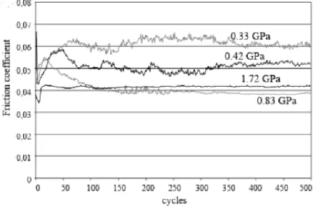
Figure 22. Influence of contact pressure in the friction coefficient for IF-WS2 in PAO (77). ... 47
Figure 23. Temperature effect on the friction coefficient for IF-MoS2 nanoparticles (90). ... 48
Figure 24. Composition of the tribofilm generated by WS2 NP in PAO oil at 100°C proposed by Ratoi et al. (103)... 49
Figure 25. Friction coefficient of IF-MoS2 nanoparticles in PAO and in a fully formulated oil at 80°C (104). ... 49
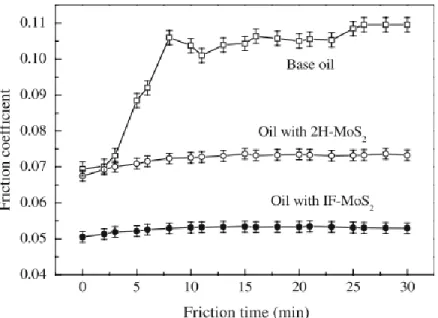
Figure 26. Friction coefficient for PAO alone, MoS2 in PAO and Rhenium doped nanoparticles in PAO oil (106, 107). ... 51
Figure 27. Tribological response of a PAO base oil containing various concentrations of IF-MoS2 and succinimide-based dispersants (104)... 52
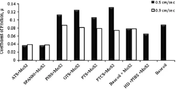
Figure 28. Friction coefficient of MoS2 nanoparticles suspended in oil using different dispersants (109). ... 53
Figure 29. Friction coefficient of MoS2 doped and un-doped gray cast iron surfaces lubricated with mineral oil and nanoparticles containing oil (110). ... 54
Figure 30. Friction coefficient of WS2 and MoS2 nanotubes and fullerene like nanoparticles in PAO base oil (92). ... 55
Figure 31. Evolution of the friction coefficient of IF-MoS2, IF-WS2 and platelets of 2H-MoS2 in PAO (96). ... 56
Figure 32. Friction coefficient of IF-MoS2 nanoparticles of different size in PAO6 (116). ... 56
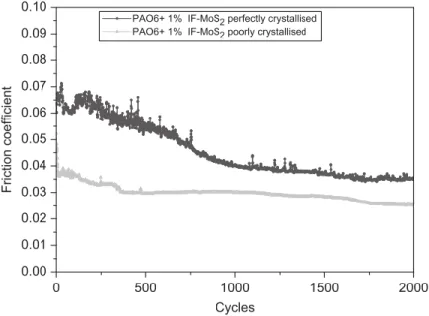
Figure 33. Tribological reponse of perfectly crystallised and poorly crystallised IF-MoS2 nanoparticles (84). ... 57
Figure 34. Influence of the surface roughness in the tribological behavior of NT-MoS2 (91). ... 58
Figure 35. DLC coating on various engine components (source: Sulzer Group) ... 59
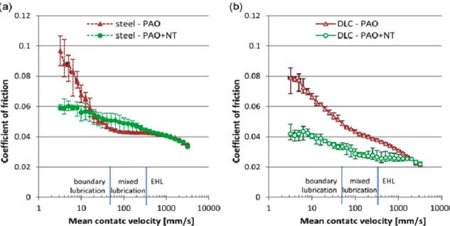
Figure 36. Friction coefficient on a) steel and b) DLC surfaces lubricated with PAO base oil and base oil with MoS2 nanotubes (118). ... 60
Figure 37. Tribological response of a fully formulated engine oil and of the same oil doped with IF-MoS2 nanoparticles at different concentrations (104). ... 62
Figure 38. Correlations found by Jenei et al. (121) ... 63
15 Figure 40. TEM images of WS2 nanoparticles used for the tribological tests: (a) cluster with IF
nanoparticles and 2H-WS2 sheets, (b) spherical shape WS2-IFLNP and (c) polyhedral shape
nanoparticle. ... 70
Figure 41. Particle size distribution of the nanoparticles. ... 70
Figure 42. XPS spectra of WS2 nanoparticles: (a) W4f region, (b) S2p region. ... 71
Figure 43. MTM schema (left) and picture (right) (source: PCS instruments) ... 73
Figure 44. Traction curves for PAO base oil (doted lines) and PAO + WS2 (full lines) at 30°C (blue, left) and 100°C (red, right) measured at 0.3 m/s ... 74
Figure 45. Stribeck curves obtained for PAO (dotted lines) and PAO + WS2 nanoparticles (full lines) at 30°C (blue, right) and 100°C (red, left). ... 75
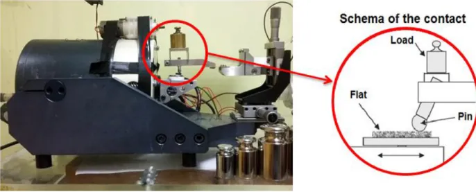
Figure 46. Picture of the pin-on-flat tribometer used for the experiments and schema of the contact. ... 76
Figure 47. Friction coefficient for the nanoparticles (full line) and the reference (dotted line) as a function of cycles at room temperature (blue, left) and 100°C (red, right) ... 77
Figure 48. Wear coefficient calculated for PAO and PAO + WS2 nanoparticles at room temperature (blue) and 100°C (red)... 78
Figure 49. Wear scars of the pin when lubricating smooth surfaces with PAO and PAO + WS2 nanoparticles at room temperature (blue, left) and 100°C (red, right). ... 78
Figure 50. Tungsten and sulfur XPS spectra of the tribofilm by the nanoparticles at room temperature and at 100°C ... 79
Figure 51. TGA curve of the sample bought from nanomaterials company. ... 80
Figure 52. Composition of the tribofilm generated by WS2 NP in PAO oil at 100°C proposed by Ratoi et al. (103)... 81
Figure 53.TEM images and EDX spectra of the tribofilms formed with the WS2 nanoparticles in PAO at room temperature (a and c) and 100°C (b and d). The yellow doted lines delimit the tribofilm. ... 82
Figure 54. Friction coefficient as a function of cycles for the WS2 nanoparticles (red) and the WO3 (green) nanoparticles in PAO base oil at 100°C. ... 83
Figure 55. Wear scars after the test for the WS2 nanoparticles (red, left) and the WO3 nanoparticles (green, right). ... 84
Figure 56. Friction coefficient as a function of the cycles for PAO (dotted lines) with and without (full lines) WS2 nanoparticles on rough surfaces at room temperature (blue, left) and 100°C (red, right). ... 85
Figure 57. Wear scars of the pins when lubricating rough surfaces with PAO and PAO + WS2 nanoparticles at 100°C (blue, left) and 100°C (red, right). ... 85
Figure 58. Tungsten XPS spectra of the tribofilm formed at room temperature and at 100°C ... 86
Figure 59. Wear scars of experiments carried out at 100°C on the rough flats, where a) and b) correspond to the images of the complete wear track and a closer view of the rough flat lubricated with PAO while c) and d) correspond to those of the flat lubricated with the nanoparticles in PAO. ... 87
Figure 60. Chemical mapping of the wear track obtained when using the industrial WS2 nanoparticles on a rough flat at 100°C ... 88
16
Figure 61. Closer looking of the zones with important tungsten and sulfur signals. ... 89
Figure 62. Iron, tungsten and sulfur chemical mapping of the wear track for the cross FIB cut. The red line indicates the zone where the transversal cut was done. ... 89
Figure 63. SEM image of the FIB transversal cut showing the groove. ... 90
Figure 64.TEM image of the groove. The red rectangle shows the area where EDX mapping was done. ... 90
Figure 65. Chemical mapping of the red rectangle area shown in Figure 64, proving the presence of tungten and sulfur inside the groove. ... 91
Figure 66. Presence of some nanoparticles and sheets of WS2 inside the groove. ... 92
Figure 67. Friction curves obtained for the two step experiments on the rough (red) and the smooth (blue) surfaces. The yellow line represents lubricant change from PAO + WS2 to PAO alone. ... 92
Figure 68. Friction curves obtained for the two step experiments on the rough surfaces with either MoDTC or WS2 in PAO. The yellow line represents lubricant change to PAO alone. ... 93
Figure 69. Lubricants oxidation schema. ... 95
Figure 70. Generic structure of diphenylamines. ... 95
Figure 71. Friction curves obtained for the diphenylamine antioxidant in PAO (purple) and for the WS2 nanoparticles in the presence of the antioxidant at 100°C (orange 1 and 2). ... 96
Figure 72. XPS spectra of the tribofilm formed by the nanoparticles in the presence of a diphenylamine antioxidant; a) survey scan; b) W4f spectrum of the tribofilm that gave the friction curve marked as 1 in Figure 71 and c) W4f spectrum of the tribofilm that gave the friction curve marked as 2 in Figure 71 ... 97
Figure 73. Coefficient of friction as a function of cycles for the different samples. ... 98
Figure 74. Average friction coefficient for the different samples. ... 99
Figure 75. Wear scars of a) PAO + WS2, b) PAO + ZDDP and c) PAO + WS2 + ZDDP. ... 100
Figure 76. Wear coefficient for the different samples. ... 100
Figure 77. XPS spectra of the tribofilm formed by the nanoparticles in the presence of ZDDP additive on the smooth steel flat; a) survey scan; b) W4f energy region and c) S2p energy region. ... 102
Figure 78: XPS depth profile on the tribofilm formed by the nanoparticles in the presence of ZDDP; a) Evolution of the concentration of all the elements, b) zoomed on tungsten and sulfur elements. ... 104
Figure 79. a) TEM image of the tribofilm showing the presence of WS2 sheets, and the presence of a WS2 nanoparticle embedded in the tribofilm formed by the nanoparticles in the presence of ZDDP. b) EDX spectra recorded from the tribofilm and c) EDX spectrum recorded from the nanoparticle. ... 105
Figure 80. TEM images of the tribofilm showing the presence of WS2 sheets in the tribofilm formed by the nanoparticles in the presence of ZDDP additive... 105
Figure 81. Friction coefficient for the ZDDP and nanoparticles containing samples. ... 106
Figure 82. Friction coefficient and wear scars obtained for the rough surfaces lubricated by the different samples. ... 108
Figure 83. XPS spectra of the tribofilm formed by the nanoparticles in the presence of ZDDP additive on the rough steel flat; a) survey scan; b) W4f energy region and c) S2p energy region. ... 109
17 Figure 84.Schema of the chemical structure of a calcium phenate detergent. ... 111 Figure 85. Results obtained for the samples containing both anti-wear (AW) and detergent
additive with (red) and without (blue), a) friction curves; b) ERC curves... 112 Figure 86. Wear scars for the sample containing ZDDP and detergent without (left) and with
(right) the nanoparticles ... 112 Figure 87.Friction curve for the detergent in PAO as a function of cycles and wear scar of the pin
at the end of the test. ... 113 Figure 88. XPS survey scan of the tribofilm formed for both samples after 100 cycles ... 114 Figure 89. Images of the worn surfaces (pin and flat) lubricated by the reference sample at the
end of the test and after 100 cycles. ... 115 Figure 90.XPS depth profile on the tribofilm formed by the sample containing the nanoparticles
and both anti-wear and detergent additives. ... 116 Figure 91. XPS spectra of the C1s peak showing the different contributions present in the
tribofilm. ... 117 Figure 92. XPS spectra of the tribofilm formed by both samples at the end of the test a) survey
scan b) elementary depth profile of the tribofilm formed by the reference sample and c)
elementary depth profile of the tribofilm formed by the sample that contained the nanoparticles .... 119 Figure 93. TEM images of the FIB cross cut of the tribofilm formed by the nanoparticles in the
presence of calcium phenate and ZDDP. ... 121 Figure 94. Schema of the FZG tests rig ... 130 Figure 95. FZG testing program (rotational speed and temperature were constant across the load
stages) ... 130 Figure 96. XPS spectra of the manganese phosphate coating zoomed on a) P2p energy region, and
b) Mo2p3 energy region. ... 132 Figure 97. SEM image of the manganese phosphate coating present on the steel surface of the
gears before the transmission test. ... 133 Figure 98. Surface of the gears after the experiments for a) Sample B and b) Sample D... 134 Figure 99. Gear tooth terminology ... 135 Figure 100. XPS spectra of the tribofilm formed on the gear surface for sample B, a) zoomed on
the W4f energy region (b) and S2p energy region (c). ... 136 Figure 101. XPS spectra of the tribofilm formed on the gear surface for sample D. ... 137 Figure 102. SEM images of the teeth after test for sample B and D showing the presence of cracks;
(a) Surface of the tooth for sample B, (b) cracks for sample B, (c) surface of the tooth for sample D, (d) cracks for sample D. ... 138 Figure 103. SEM image of the cross-sectional cut made from a tooth of the gear after the test for
sample B on a spalled zone; a) localization of the cracks; b) zoom of the red rectangle showing
the presence of deep cracks. ... 139 Figure 104. Chemical mapping characterization of a spall observed for sample B. ... 140 Figure 105. Chemical mapping characterization for sample B where different defect on the surface
can be observed. ... 141 Figure 106. Crack propagation by oil hydraulic pressure (19). ... 142 Figure 107. Proposed mechanism against crack growth. ... 143
18 Figure 108. Localization of the cross-sectional cut made by FIB on the surface of the gear tooth
(Sample B). The arrow represents the direction of the cut. ... 143 Figure 109. a) TEM image of the FIB preparation (Sample B), b) zoom-in at the beginning of the
crack, and c) zoom-in on a zone containing sheets of WS2. ... 144 Figure 110. EDX spectra of a) the tribofilm and b) of the layer formed into the crack. ... 145 Figure 111. Localization of FIB cut number two (Sample B). ... 147 Figure 112. TEM image of the FIB cut made in the bulk of the steel (Sample B) showing: a) the
presence of a gray layer on the walls of the crack, b) a zoom of the upper right side of figure a), c) a zoom of the red circle of the figure b), and d) a zoom of the figure c) revealing the presence
of WS2 sheets in the border of the gray zone. ... 147 Figure 113. EDX analysis of the spherical particles observed in Figure 112a. ... 148
19
Notations
Elastohydrodynamic film thickness
Ra Average roughness
µ Friction coefficient
Lambda ratio
Abbreviation and acronyms
AFM Atomic Force Microscopy
AW Anti-wear
BL Boundary Lubrication
CVT Continuously Variable Transmission
CO Carbon monoxide
COF Coefficient Of Friction
DLC Diamond-Like Carbon
DOC Diesel Oxidation Catalyst
DPF Diesel Particulate Filter
EDX Energy Dispersive X-ray spectrometer
EP Extreme Pressure
ECR Electrical Contact Resistance
FIB Focused Ion Beam
FM Friction Modifier
HD Hydrodynamic lubrication
HFRR High Frequency Reciprocating Rig
IEA International Energy Agency
IF Inorganic Fullerene-like
MoDTC Molybdenum Dithiocarbamate
MTM Mini Traction Machine
NMHC Non-Methane Hydrocarbons
NOx Nitrogen Oxides
NP Nanoparticle
NT Nanotube
NS Neutral Solvent
OFM Organic Friction Modifiers
PAO Polyalphaolefin
PM Particulate Matter
S Solvent
SCR Selective Catalytic Reduction
20
SSU Second Saybolt Universal
TDS Total Dissolved Solids
TEM Transmission Electronic Microscope
TGA Thermogravimetric Analysis
THC Total hydrocarbon
XANES X-ray Absorption Near Edge Structure
XPS X-Ray Photoelectron Spectroscopy
21
State of the art
The aim of the State of the art part is to present a general overview about lubrication science in the automotive industry, followed by a synopsis about the research that has been done on metal dichalcogenide nanoparticles. The first part includes the description of tribology and its fundamental principles as well as the generalities of lubricants and their composition. The role of the different additives is also presented. The second part consists on a bibliographic review of nanoparticles as lubricant additives which exposes the results obtained by different research groups around the world.
23
1. Industrial context
It is known that energy is the main fuel for economic and social development and that its demand has always been linked to population growth. Generation of energy can be done from different sources such as coal, oil and natural gas (among others). However, for decades, oil has been the main source of the energy we used. According to the International Energy Agency (IEA), 64% of the oil consumed in 2012, was consumed by the transport industry (1) as illustrated by Figure 1. Research done by the VTT Technical Research Centre of Finland revealed that, in passenger cars, one third of the fuel energy is used to overcome friction on engine, transmission, tires and brakes (2). This means that 208,000 million liters of fuel (gasoline and diesel) were used to overcome friction in 2009. The global energy demand for transportation is projected to increase by 40 percent from 2010 to 2040 (3), at the same time the vehicle fleet is expected to duplicate to 1.7 billion in 2035 and is expected to be 2.2 billion in 2050 (4). As a consequence, research in tribology has been specially focused in the development of low friction materials and more efficient lubricants, which may be able to reduce fuel consumption, increase energy efficiency and thus reduce emissions.
Figure 1. World energy consumption from 1971 to 2012 by fuel in million tonnes of oil equivalent (Mtoe) and oil world consumption by sector (1).
Since 1992, when the Earth Summit was signed in Brazil during the United Nations Conference on Environment and Development, the governments recognized the need to redirect international plans and policies to reduce vehicle emissions. In the European Union, the acceptable limits for exhaust emissions of new cars are defined by the European Emission Standards. These regulations concern emissions of nitrogen oxides (NOx), total hydrocarbon (THC), non-methane hydrocarbons (NMHC), carbon monoxide (CO) and particulate matter (PM). The emission standards have been progressively tightened. Figure 2 illustrates the evolution of these regulations concerning NOx and PM for diesel passenger cars. Euro 6 standard became mandatory from the beginning of 2015.
24
Figure 2. Evolution of Euro Emissions Standards for diesel passenger cars (taken from: http://www.clm.co.uk/diesel-emissions-crackdown/)
In order to improve energy efficiency and to reduce emissions, manufacturer’s strategies include developments in lubrication and surfaces to minimize internal friction and weight of the vehicle. The use of lighter materials and the downsizing of components would reduce the automobile weight. However, reducing the size of contacting components will probably cause friction and wear to increase. Lubricants must be able to work under more severe conditions to guarantee lifespan of the mechanical parts of cars. For this reason, research in tribology, the science of friction and wear needs to be done.
2. Friction and wear principles
Despite the fact that humanity has been facing tribology problems since a long time ago, it was not until the 60’s that this term was employed for the first time. The term tribology comes from the Greek word “tribos” which means “rubbing” and from the suffix “ology” which means “the study of”. Therefore, tribology is the study of rubbing or the study of things that rub. Nowadays, tribology is known as the study of friction, lubrication and wear.
25
2.1 Friction principles
Friction is defined as the resistance encountered when one body moves tangentially over another with which it is in contact. Friction force always acts in the opposite direction to that of the relative displacement between the contacting surfaces and is a function of the normal load of the contact. It is also the principal cause of wear and energy dissipation. As a matter of fact, friction has been a part of humanity’s history since its very beginning. In ancient Egypt, wooden sledges where used to haul the heavy stones for the construction of the pyramids. Later, at around 3000 BCE, the invention of the wheel was also a response to friction.
Leonardo Da Vinci (1452-1519) is considered the first scientist that studied the basics of friction. However, Guillome Amontons (1663-1705) was the first to formulate the friction laws. Further understanding of friction phenomena was made by Hertz, Reynolds, Coulomb, Bowden and Tabor. Friction between moving surfaces can be reduced by the use of lubricants. Lubricants can be solid, gases or liquids. In the automobile industry, lubricants are liquids composed mainly of base oil and a package of additives.
In the case of liquid lubrication, three different regimes can be distinguished: full film or hydrodynamic, mixed and boundary lubrication. These are based on the lambda parameter or specific film thickness, which is the ratio of the fluid film thickness to the surface roughness as defined by the equation 1.
(Eq 1)
Where is the elastohydrodynamic film thickness for smooth surfaces and
and
are the
roughness values of the two bearing surfaces. All the lubrication regimes and their relationship to the lambda parameter are illustrated in the Stribeck curve in Figure 3. Full film or hydrodynamic lubrication (HD) regime occurs when the two surfaces in motion are completely separated by a film of fluid, this means that the lubricant film is thicker than the height of the asperities. On the other hand, boundary lubrication (BL) occurs when the two surfaces are mostly in contact with each other even though a fluid is present. Mixed lubrication (ML) is a cross between boundary and full film lubrication where the bulk of the surfaces are separated but the asperities are in contact.
26
Figure 3. Stribeck curve showing the different lubrication regimes as a function of the film thickness, the viscosity and the normal load.
2.2 Wear principles
Wear is defined as the removal or displacement of material from one body when subjected to contact and relative motion with another, in other words when subjected to friction. There are several types of wear. However, the most representatives and important ones are: abrasive, adhesive, rolling contact fatigue and corrosive. In reality, wear does not normally take place through just one wear mode but through a combination of them. An explanation about the wear modes in presented below and schematic images of each wear mode are illustrated in Figure 4.
Figure 4. Schematic images of the wear modes (5).
27 Abrasive wear occurs between surfaces of different relative hardness. In this wear mechanism
the asperities of the hardest material scratch the softer one. This mode is also known as Scratching. The three different abrasive modes are shown in Figure 5: microcutting, wedge forming and ploughing. The wear particles have different forms depending on these three modes. In the first one, curled and long ribbon-like wear particles are formed; in the second one, wedge-like particles are formed at the tip of the grooving asperity while in the third one a shallow groove is formed on the surface but repeated sliding and accumulation of plastic flow are necessary to generate a wear particle.
Figure 5. TEM images of the different abrasive wear modes (6)
Adhesive wear occurs when adhesive bonding strength of the contact interface between two
surfaces can resist their relative sliding. Thus, deformation occurs under the compressed zone initiating a crack which propagates in the combined fracture mode of tensile and shearing until it reaches the contact interface and creates a wear particle. Wear particles can leave the contact interface or stay on either surface. Transfer and retransfer from one surface to the mating surfaces take place in many cases. Compatibility of the materials is important for this wear mechanism.
Corrosive Wear takes place in the case where a tribochemical reaction produces a layer on the
surface which is continuously removed by friction. This layer behaves in most of the cases differently from the bulk material.
Rolling contact fatigue is due to the stress developed in the subsurface of the material under
repeated or cyclic loading conditions. This can cause subsurface delamination and cracking. In the case of metallic materials, shallows are formed by the ploughing mode and after repeated contact of abrasive sliding at the same grooves, plastic burnishing becomes more predominant and after a critical number of cycles fatigue mode appears.
28
3. Tribology in the automotive industry
Vehicles are one of the most common machines used nowadays. A car consists in thousands of different parts which are commonly in motion. Thus, we can find many hundreds of tribological parts in cars like bearings, gears, tires among many others. All the lubrication regimes and the wear modes presented above are met in automotive applications. According to Tung et al. (7) for the purpose of classifying tribological components, vehicles can be divided into engine, transmission and ancillaries (tires, brakes and windshield wipers). In the framework of this investigation, only the engine and transmission will be discussed and special focus will be put on transmission failure.
3.1 Engine
Engines or motors are machines designed to convert energy into mechanical motion. Car engines are internal combustion engines which produce the power necessary to move vehicles by controlled explosions. Car engines use fuel, such as petrol or diesel, which is ignited to produce the power required to move the vehicle. The power is then transferred to the driveshaft via the transmission drive. Most engines use a four stroke combustion cycle which consists of: intake, compression, combustion and exhaust. The cycle is repeated in quick succession to generate the required power. The different components of an engine can be seen in Figure 6.
29 Engines work under a wide range of operating conditions of speed, temperature and load. The lubrication system makes sure that every moving part in the engine gets lubricant so it can easily move. According Taylor et al. (8) 80% of the mechanical losses of an internal combustion engine are due to friction. Some examples of moving parts where lubrication is needed are pistons which slide in the cylinders and bearings that allow rotation of the crankshaft and camshafts. A representation of the engine lubrication system can be observed in Figure 7. The lubricant is taken from the sump by the pump that drives it to the oil filter to remove sludge as well as potentially abrasive particles such as debris resulting from engine wear. It is then squirted under high pressure onto the main bearings and the cylinder walls. After the entire engine is lubricated, the lubricant is collected in the sump where the heat is transferred to the surrounding air and the cycle is then repeated.
Figure 7. Engine lubrication system (source: Encyclopedia Britannica, Inc.).
Therefore, all the lubrication regimes can be easily found in engines. In fact, some components are known to operate in specific lubrication regimes as illustrated in Figure 8.
30
Figure 8. Lubrication regimes for engine components.
As a result, lubricants used in engines must resist the high heat of combustion and must not degrade when exposed to combustion products. They must also be capable of removing metal debris away from the contact zones, produced during the running in of rough surfaces, and to protect matting surfaces working under the mixed and boundary lubrication regimes as it is the case of the valve trains.
Proper lubrication yields to reduction on both fuel and oil consumption and increase in engine lifespan. Thus, improvements in tribology have a direct impact on these items and should focus on the reduction of harmful exhaust emissions. According to Culley et al. (9, 10) an increasing concern with modern engine oils is the influence of presence of phosphorus that deteriorates the emission systems components by poisoning the after treatment catalysts.
3.2 Transmission
The transmission system is responsible for the power transfer from the engine to the drive wheels. This is done by variation of torque from the engine through manual gear operation, or torque conversion in the case of automatic transmission cars. A car’s transmission system enables the engine to provide a wide range of output speeds which allow vehicles to function in different driving conditions by the use of different gears.
The first stage of the transmission system is the clutch which is then followed by the gearbox. Manual transmission cars have normally four or five forward speeds, one reverse and a neutral position. Figure 9
31 shows one of the most common configurations of a five-speed gearbox. Power enters the transmission though the input shaft which is connected to the engine via the clutch. When the cutch is fully engaged, the layshaft is always turning. All the helical gears on the layshaft are permanently attached to it so they all turn at the same rate. They mesh with a series of gears on the output shaft that are mounted on sliprings so they permanently spin around the output shaft but don’t make it turn. The gear level which is operated by the driver is connected to selector rods and forks that move the synchromesh units back and forth and allows transferring movement from the layshaft to the output shaft, according to which gear is selected. All this is done by the action of friction so lubricants must be used.
Figure 9. Typical five-speed gearbox (source: www.carbibles .com)
Gear lubricants must have good thermal and oxidative stability, extreme pressure resistance and protection against wear to reduce the failure risk. The most common form of failure in gears is known to be rolling contact fatigue (11, 12).
3.2.1 Failure of gears
3.2.1.1 Surface contact fatigue principles
Rolling contact fatigue is one of the most common wear modes. As explained in section 2.2, it occurs when two surfaces in contact experience Hertzian stress of a great magnitude and number of cycles. This localized stress results when curved surfaces are in contact under a normal load. So it can be
32 observed not only in gears but also in bearings where the contact geometry and the motion of the rolling elements produce an alternating subsurface shear stress. As a matter of fact, all surfaces in rolling and/or sliding contact are exposed to fatigue.
Fadjdiga et al. (13) defined fatigue as a kind of damage caused by changes in the material microstructure which results in crack initiation followed by crack propagation. Therefore, the initiation of cracks represents one of the most important stages in fatigue process.
The chemical and physical properties of lubricants play a significant role in fatigue wear (14). The lambda parameter or specific film thickness, water content and lubricant additives are all considered to have significant effect on fatigue life.
The lambda parameter is considered to be an important parameter affecting fatigue life of bearings as illustrated in Figure 10. Consequently, the selection of lubricants with a proper viscosity is important to ensure longer lifespan of the bearings.
Figure 10. Relative fatigue life as a function of film parameter (15)
Water content has also proven to have a detrimental effect on rolling contact fatigue life. Different research groups have demonstrated that water contents of around 1% may reduce contact fatigue life of mineral (16, 17) and hydraulic oils (18) by 40-50%. Water molecules produce embrittlement of the steel by the production of atomic hydrogen when they reach the highly reactive surface of cracks as illustrated in Figure 11. The use of additives able to neutralize protons, sequester water or form hydrophobic films may help deal with this problem.
33
Figure 11. Effect of water on the propagation of cracks (19).
Some lubricant additives may also have a significant influence on contact fatigue life. This will be discussed below.
3.2.1.2 Rolling contact Fatigue in Gears
Gear drives have non conformal interacting surfaces and have both rolling and sliding action at the teeth interfaces. Due to the severe conditions and even if correctly lubricated, gear drives will eventually fail as a result of surface fatigue phenomenon. Cracks can occur anywhere on the gear tooth flank but are most likely to appear where the contact conditions are more severe (20, 21). The teeth terminology can be seen in Figure 12.
34 Below the pitch diameter, in the dedendum zone, conditions are known to be the most critical due to the fact that sliding and rolling directions are opposite. Thus, fatigue failure normally begins at this point of the teeth.
Surface fatigue modes are: pitting, micro-pitting and spalling. Even if spalling and pitting are the most common forms of surface contact fatigue, spalling results in more rapid deterioration of surface durability when particles of the material break out. Thus, it is considered as the more destructive surface failure mode for gear contacts. The presence of cracks in the material promotes and accelerates spalling. Cracking can start either at the surface or in a subsurface level when defects and inclusions are present in the material (11, 20, 22, 23). Both kinds of cracks propagate and subsurface cracks may open to the surface. Cracks can occur anywhere on the gear tooth flank but are most likely to appear where the contact conditions are more severe (20, 21)
In 1935, Way, et al. (24) suggested that pit nucleation is brought about by the propagation of a tiny surface crack due to oil hydraulic pressure caused by oil penetrated into the crack. Later, Kaneta, et al. (25) proved that oil sealed into the cracks do promote crack propagation. It has been suggested that the process occurs in three stages: a crack opening phase caused by traction forces ahead of the rolling contact, followed by the filling of the crack by the liquid lubricant which is finally squeezed when the traction forces and contact stress close the crack (26). Pit nucleation is also thought to be due to hydrogen embrittlement. In fact, it has been shown that hydrogen decreases dramatically rolling contact fatigue life (27-29).
The role of additives in the formation and propagation of cracks is not completely understood. Special interest has been paid these last past years to the effect of anti-wear and extreme pressure additives on rolling fatigue life. In some instances, these additives have demonstrated to be able to increase the rolling contact fatigue life of gears (30-32). In others, results have shown detrimental effect on pitting life (33-36) which scientist link to chemical reactivity of the additive that would attack the metal surface promoting crack initiation by the creation of corrosion pits. On the other hand, other researchers state that the effect of these additives depends on their concentration in the oil (33, 37-39). An increment of the fatigue life can be obtained at low concentrations while a decrement is observed at high concentrations. The fact that additives can go inside cracks and react with crack faces was demonstrated for the first time by Meheux et al. (40).
The use of solid additives has also been studied. Arizmendi et al. (41) tested the effect of a solid nonstoichiometry inorganic glassy compound consisting of B, P, Mg, and K (known as nsic-bp1) oxides with a particle size of 16 µm, and a solid MoS2 of colloidal grain size, on fatigue life. Their results show that both solid particles improve more than twice the fatigue life of the base oils. Only the results obtained with the first solid additive were analyzed. No oxidation of the base oil was observed with this additive. The authors proposed that all the heat was used for softening the solid compound, so there was no heat available for the oxidation of the base oil, thus inhibiting the generation of hydrogen preventing crack nucleation and growth. Other alternative mechanism proposed by the authors is the formation of a protective film of the softened compound which may delay crack initiation produced by chemical attack from active substances in the oil, and would also inhibit oil penetration once the cracks
35 are formed, delaying crack propagation. Nevertheless, no chemical analyses were done on the surfaces to observe such protective film, nor physical analyses where made to observe the presence of cracks in the material. On the other hand, Rico et al. (42) have shown that PTFE nanoparticles used as additive in both mineral and synthetic base oils at concentrations lower than 3% increase the fatigue life of steel. The authors measured the contact angle between the counter parts and found that it decreased in the presence of PTFE. This led them to the conclusion that these nanoparticles improve the adsorption phenomena increasing the lubricant’s unctuosity. They also claim that simple mechanical interposition of PTFE particles between the surfaces could protect them from fatigue. However, no surface analyses were done to observe the presence of cracks in the steel.
To resume, rolling contact fatigue is known to be one of the most common forms of failure fatigue in gears. Thus, the reduction of wear in gearboxes requires the use of powerful lubricants able to minimize the disastrous consequences of the contact fatigue.
3.3 Lubricant composition and function
As it has been stated before, a lubricant is a substance that is used to reduce friction between moving surfaces. Lubricants perform a number of critical functions: to provide cooling, transport debris away from the interface, prevent deposits on the surfaces, among others. Additionally, they must be effective in all the lubrication regimes. In order to help the oils accomplish all these tasks, additives are used. Additives are substances that are mixed into the base oil either to suppress or enhance its intrinsic properties or to add properties it does not have by itself. The composition of a lubricant is illustrated in Figure 13. The concentration and the chemical nature of the additives directly depend on the application in which it is used. In the automobile industry, lubricants need good oxidation resistance, suitable low and high temperature viscosities and good cleaning and dispersing ability. On the other hand, metalworking lubricants need antiwear performance, corrosion control and cooling ability.
36
3.3.1 Base oil
Base oils can be classified depending on their origin into mineral oils or synthetic lubricating oils
Mineral oils are the most commonly used throughout the industry. They are produced from
crude oil by distillation. Their properties depend both on the composition of the original crude oil and the processes used for its manufacture which can be solvent extraction or hydrotreatment. They can be classified into: paraffinic and iso-paraffinic base oils. Paraffinic base oils have a good oxidation stability and high viscosity index (of around 100). However their high molecular weight can produce crystallization even at room temperature.
On the other hand, iso-paraffinic base oils, which have a lower viscosity index, don’t present this problem. They are named after their viscosity measured at 37.8°C in Second Saybolt Universal (SSU) and the letter S (solvent) or NS (neutral solvent). In this group, the naphthenic base oils can also be found. They have low oxidation stability but good properties at low temperatures.
Synthetic oils are artificial substitutes for mineral oils. They are obtained by chemical synthesis.
As a consequence, they have better properties than the natural base oils but are more expensive. The most common synthetic base oils used in the automobile industry are the polyalphaolefines (PAO) which are composed of carbon and hydrogen, and the esters composed of oxygen, carbon and hydrogen.
3.3.2 Lubricant additives
As said before, lubricants must have a good performance in all the lubrication regimes, so additives are added to the base oils to improve its performance. The additives can be present in a lubricant at concentrations ranging from 1 to 30%. Their concentration and chemical nature depend on the lubricant’s further use. Additives can act to protect the counter surfaces, to improve the base oil performance and to protect the lubricated surfaces. The most commonly used additives and their classification according to their function is illustrated in Figure 14. The specific function of each additive is described below. A special focus will be made on the mechanism of the tribological active additives.
37
Figure 14. Classification of the additives used in lubrication by the function they accomplish.
Antioxidant
Oxidation leads to oil thickening (increase of the viscosity), sludge and deposit formation and corrosion. Thus the use of antioxidants delays the degradation of the oil that is activated by the presence of air, high temperatures and acids. Antioxidant additives reduce then the oxidation rate of the base oil which determines the useful life of the lubricant. Aromatic amines, sulfur and phosphorous compounds are used as antioxidant additives.
Corrosion inhibitors
These additives protect metal surfaces against chemical attack by the adsorption onto the surface via a high polar group to form a protective film. Some used molecules are amine succinate and alkaline earth surfonates.
Pour point depressant
Polymeric compounds are used to interfere the crystallization process of paraffin present in oil improving the flow properties at low temperatures.
Viscosity modifier
The viscosity modifier additives are used to improve the viscosity temperatures properties of lubricants. High molecular polymers are used to increase the oil viscosity of the oil at high temperatures by steric effect. Poly-alkyl-methacrylate and olefin’s copolymer are widely used.
•Antioxidant
•Corrosion inhibitors •Antifoam
Protection of the base oil
•Pour point depressant •Viscosity modifier
Improvement of the base oil
•Detergent •Dispersant
•Antiwear and extreme pressure •Friction Modifier
Protection of the lubricated
surfaces
38
Detergents
Detergents keep the surfaces clean by preventing the formation of carbon-based deposits at high temperature. They have a micellar structure with an alkaline core surrounded by surfactant chains. They can have neutral pH or be overbased in order to neutralize acid compounds which could be generated. Sulfonates, phenates, salicylates and phosphonates are commonly used.
Dispersants
Dispersants are non-metallic or ashless cleaning agents that solubilize and disperse contaminants. They are fully organic compounds with polar head and hydrocarbon tail. Succinimides are the most widely used dispersant.
Antifoam
These additives are used to inhibit foaming caused by dispersants and detergents. Mainly silicon based molecules are used.
Anti-wear and extreme pressure
These additives form a protective film on the surface by chemical reaction. Typical additives contain sulfur and or phosphorus. The most widely used is Zinc dialkyl dithiophsphate (ZDDP).
Friction modifiers
The friction modifiers additives are used to reduce friction between the counter surfaces. Organomolybdenum compounds are the most widely used friction modifier additives. Through chemical reaction they produce a tribofilm on the surface composed of sheets of MoS2 which allows friction reduction. Molybdenum dithiocarbamate (MoDTC) is the most used organomolybdenum compound used in the automobile industry.
Therefore, the additives with a tribological action are the friction modifiers, the anti-wear and the extreme pressure additives. They are active in the boundary lubrication regime where they can create a tribofilm to protect the surfaces and allow reduction of wear and/or friction. So in this section, the lubrication mechanisms of these additives under severe conditions will be explained.
3.3.2.1 Tribological active additives
3.3.2.1.1 Zinc-dialkyl-dithiophosphate (ZDDP)
Despite the fact that the ZDDP additive has been used as the primary anti-wear additive, it was first used as corrosion and oxidation inhibitor in engine oils (43) and it also has extreme-pressure properties (44). Its molecular structure is shown in Figure 15.
39
Figure 15. Molecular structure of ZDDP molecule.
When tribo-stressed in a lubricated tribological contact under severe contact conditions, ZDDP molecules form an anti-wear tribofilm on the steel rubbing surfaces which is consumed and regenerated continuously preventing steel/steel contact. Chemical analyses have demonstrated that this tribofilm is mostly composed of amorphous zinc/iron polyphosphates with variable chain lengths with inclusions of ZnS and FeS (43). A schematic representation of the tribofilm formed by ZDDP under friction and shear is illustrated in Figure 16.
Figure 16. Schematic diagram of the composition of ZDDP tribofilms (43).
The anti-wear properties of ZDDP seems to be linked to the ability of phosphate glasses to digest iron oxides that would cause abrasive wear to produce relatively soft iron phosphate (45, 46).
With the aim to elucidate the mechanisms of this tribofilm formation research has been done on the reactions of the molecule in the oil and on its adsorption on the surfaces.
3.3.2.1.1.1 Reactions of the molecule in oil
The literature suggests that ZDDP can show different types of chemical behavior in solution: antioxidant activity and thermal degradation.
It has been shown that ZDDP can not only decompose hydroperoxides (47) but also peroxy-radicals (48) which are at the heart of the hydrocarbon oxidation chain reaction. Additionally, ZDDP can sequester pro