HAL Id: tel-02061745
https://tel.archives-ouvertes.fr/tel-02061745
Submitted on 8 Mar 2019
HAL is a multi-disciplinary open access archive for the deposit and dissemination of sci-entific research documents, whether they are pub-lished or not. The documents may come from teaching and research institutions in France or abroad, or from public or private research centers.
L’archive ouverte pluridisciplinaire HAL, est destinée au dépôt et à la diffusion de documents scientifiques de niveau recherche, publiés ou non, émanant des établissements d’enseignement et de recherche français ou étrangers, des laboratoires publics ou privés.
Contribution to the manufacturing and the
understanding of the thermal behaviour of capillary
structures dedicated to Loop Heat Pipes
Rémi Giraudon
To cite this version:
Rémi Giraudon. Contribution to the manufacturing and the understanding of the thermal behaviour of capillary structures dedicated to Loop Heat Pipes. Thermics [physics.class-ph]. Université de Lyon, 2018. English. �NNT : 2018LYSEI003�. �tel-02061745�
N° d’ordre NNT : 2018LYSEI003
THESE de DOCTORAT DE L’UNIVERSITE DE LYON
opérée au sein de
L’Institut National des Sciences Appliquées de Lyon
Ecole Doctorale
N° ED 162
(Mécanique, Énergétique, Génie Civil, Acoustique)
Spécialité: Thermique et Energétique
:Soutenue publiquement le 15/01/2018, par :
Rémi Giraudon
Contribution to the manufacturing and
the understanding of the thermal
behaviour of capillary structures
dedicated to Loop Heat Pipes
Devant le jury composé de :
BERTIN Yves Professeur (PPRIME, ENSMA, Poitiers) Président BERTRAND Ghislaine Professeur (CIRIMAT, INP, Toulouse) Rapporteur PRAT Marc Directeur de Recherche (IMFT, Toulouse) Rapporteur LAUNAY Stéphane Maître de Conférences (IUTSI, Aix Marseille Université) Examinateur SARTRE Valérie Maître de Conférences, HDR (CETHIL, INSA Lyon) Directrice de thèse LIPS Stéphane Maître de Conférences (CETHIL, INSA Lyon) Directeur de thèse GREMILLARD Laurent Directeur de Recherche (MATEIS, INSA Lyon) Directeur de thèse
Thèse préparée dans le cadre d'un partenariat entre le Centre d’Énergétique et de Thermique de Lyon (CETHIL - UMR5008 - INSA de Lyon) et le laboratoire Matériaux, Ingénierie et Sciences (MATEIS - UMR5510 – INSA de Lyon)
Département FEDORA – INSA Lyon - Ecoles Doctorales – Quinquennal 2016-2020
SIGLE ECOLE DOCTORALE NOM ET COORDONNEES DU RESPONSABLE
CHIMIE
CHIMIE DE LYON
http://www.edchimie-lyon.fr
Sec : Renée EL MELHEM Bat Blaise Pascal 3e etage secretariat@edchimie-lyon.fr Insa : R. GOURDON
M. Stéphane DANIELE
Institut de Recherches sur la Catalyse et l'Environnement de Lyon IRCELYON-UMR 5256
Équipe CDFA
2 avenue Albert Einstein 69626 Villeurbanne cedex directeur@edchimie-lyon.fr E.E.A. ELECTRONIQUE, ELECTROTECHNIQUE, AUTOMATIQUE http://edeea.ec-lyon.fr Sec : M.C. HAVGOUDOUKIAN Ecole-Doctorale.eea@ec-lyon.fr M. Gérard SCORLETTI
Ecole Centrale de Lyon 36 avenue Guy de Collongue 69134 ECULLY Tél : 04.72.18 60.97 Fax : 04 78 43 37 17 Gerard.scorletti@ec-lyon.fr E2M2 EVOLUTION, ECOSYSTEME, MICROBIOLOGIE, MODELISATION http://e2m2.universite-lyon.fr
Sec : Sylvie ROBERJOT Bât Atrium - UCB Lyon 1 04.72.44.83.62 Insa : H. CHARLES
secretariat.e2m2@univ-lyon1.fr
M. Fabrice CORDEY
CNRS UMR 5276 Lab. de géologie de Lyon Université Claude Bernard Lyon 1 Bât Géode
2 rue Raphaël Dubois 69622 VILLEURBANNE Cédex Tél : 06.07.53.89.13 cordey@ univ-lyon1.fr EDISS INTERDISCIPLINAIRE SCIENCES- SANTE http://www.edisslyon.fr
Sec : Sylvie ROBERJOT Bât Atrium - UCB Lyon 1 04.72.44.83.62
Insa : M. LAGARDE
secretariat.ediss@univ-lyon1.fr
Mme Emmanuelle CANET-SOULAS
INSERM U1060, CarMeN lab, Univ. Lyon 1 Bâtiment IMBL
11 avenue Jean Capelle INSA de Lyon 696621 Villeurbanne Tél : 04.72.68.49.09 Fax :04 72 68 49 16 Emmanuelle.canet@univ-lyon1.fr INFOMATHS INFORMATIQUE ET MATHEMATIQUES http://edinfomaths.universite-lyon.fr
Sec :Renée EL MELHEM Bat Blaise Pascal, 3e
étage Tél : 04.72. 43. 80. 46 Fax : 04.72.43.16.87 infomaths@univ-lyon1.fr M. Luca ZAMBONI Bâtiment Braconnier 43 Boulevard du 11 novembre 1918 69622 VILLEURBANNE Cedex Tél :04 26 23 45 52 zamboni@maths.univ-lyon1.fr Matériaux MATERIAUX DE LYON http://ed34.universite-lyon.fr
Sec : Marion COMBE
Tél:04-72-43-71-70 –Fax : 87.12 Bat. Direction ed.materiaux@insa-lyon.fr M. Jean-Yves BUFFIERE INSA de Lyon MATEIS
Bâtiment Saint Exupéry 7 avenue Jean Capelle 69621 VILLEURBANNE Cedex
Tél : 04.72.43 71.70 Fax 04 72 43 85 28 Ed.materiaux@insa-lyon.fr
MEGA
MECANIQUE, ENERGETIQUE, GENIE CIVIL, ACOUSTIQUE
http://edmega.universite-lyon.fr/ Sec : Marion COMBE
Tél:04-72-43-71-70 –Fax : 87.12 Bat. Direction mega@insa-lyon.fr
M. Philippe BOISSE
INSA de Lyon Laboratoire LAMCOS Bâtiment Jacquard 25 bis avenue Jean Capelle 69621 VILLEURBANNE Cedex
Tél : 04.72 .43.71.70 Fax : 04 72 43 72 37 Philippe.boisse@insa-lyon.fr
ScSo
ScSo* http://ed483.univ-lyon2.fr/
Sec : Viviane POLSINELLI Brigitte DUBOIS Insa : J.Y. TOUSSAINT Tél :04 78 69 72 76 viviane.polsinelli@univ-lyon2.fr M. Christian MONTES Université Lyon 2 86 rue Pasteur 69365 LYON Cedex 07 Christian.montes@univ-lyon2.fr
“ Is í ding di féin a scoileann an dair ” Irish proverb
Tenter de rendre heureux ses proches, et faire de la recherche sont deux activités similaires. Ce sont des travaux qui, en un sens, ne sont jamais terminés et qui demandent une remise en question permanente afin de ne pas finir par échouer.
Remerciements
Je tiens à saluer la mémoire de Stéphane Launay qui aurait dû être présent ce 15 janvier pour faire partie du jury. Le destin en a voulu autrement, mais Stéphane était dans toutes les têtes aujourd’hui.
15 janvier 2018, ca y est, la thèse est enfin soutenue. Que de chemin parcouru pour en arriver là. Et ce chemin, je ne l’ai parcouru seul. Même si aujourd’hui, c’est moi qui me suis présenté seul devant le jury, j’ai été accompagné et aidé au jour le jour. Pas une seule fois, Laurent, Stéphane ou Valérie ne m’ont laissé seul face aux problèmes rencontrés. Les réunions très régulières ont toujours été source d’inspiration pour moi. Ils ont suivi ce travail avec beaucoup de rigueur et d’intérêt ce qui m’a permis de systématiquement avancer. J’en profite pour remercier Eric, Damien, Jérôme et Florian, tous du labo Matéis, pour avoir grandement participé à la thèse en apportant leur point de vue sur la partie sciences des matériaux. Je remercie également Marian pour la formation accélérée sur la science des données qui a montré tout son intérêt lorsque le nombre de tests est trop grand. A l’heure de me remémorer ces innombrables tests effectués, ma pensée s’oriente naturellement vers l’Atelier. Chaque demande, urgente ou non a été traitée dans des délais, prévenant tout stress. Avec Christophe, les conversations sont du type :
-J’ai besoin de ça dans trois semaines au plus tard, c’est possible tu penses ? -Pas de soucis, je pense y arriver en deux.
Et seulement une semaine plus tard, la pièce arrive ! Mais s’il traite si bien les demandes, c’est qu’il est entouré des très compétents Nicolas, Xavier et avant ça Joël qui sont remerciés tout autant. J’en profite pour glisser un petit mot de remerciements également à Anthony et Serge qui m’ont permis d’utiliser mes bancs d’essais avec des logiciels d’acquisition performants. Je n’oublie pas non plus Antoine dont l’énergie débordante m’a permis d’avancer sereinement, sachant qu’il n’était jamais loin en cas de pépin. Si la thèse a pu être menée à son terme, c’est également grâce à l’activité du secrétariat qui gère toute la partie non scientifique et qui permet le plus souvent aux doctorants de se concentrer sur d’autres choses. En ce qui me concerne, j’ai principalement été épaulé par Florence et Maryline mais Christine, Silas, Rémy, Corinne, Nazaré ou encore Sophie ont à l’occasion su me dépanner et je les associe à ces remerciements. On a souvent tendance à dire « ma thèse », mais en ce qui me concerne, j’ai plutôt eu l’impression d’être au cœur d’un projet collectif où beaucoup ont apporté une ou plusieurs pièces.
Merci à Ghislaine Bertrand, Marc Prat et Yves Bertin pour avoir accepté du juger ce travail parfois éloigné de leurs thématiques de recherches respectives. Vos remarques, tant via le rapport, que le jour de la soutenance ont été très constructives et ont permis des discussions intéressantes.
Mais assez parlé boulot, j’ai également passé du temps au labo à ne pas travailler et pendant ces périodes j’ai trouvé des collègues qui sont devenus des copains et on n’a jamais donné notre part au chien quand il s’est agi de s’amuser un bon coup. Que ce soit à la coinche, au foot ou à la K-fête, j’ai passé du très bon temps avec vous tous, Aurélia, Quentin, Thibault, Sandra, Adrien, Eloïse, Martin, Loïc, Damien, Nicolas, David, Thomas, Bus, Ghady, Julie, Kevin, Léon, Etienne.
Parmi toutes ces personnes, je sors du lot Damien et Olivier. J’ai beaucoup aimé votre rapport à la science et au travail de recherche. Vous m’avez mis le pied à l’étrier en me donnant les bons filons (80 trèfle par exemple). Surtout, vous m’avez ouvert les portes de votre groupe de potes qui sont tout aussi excellents que vous (et oui les Vieux Michels, je parle de vous). Et ça, c’est inestimable. Des Rouies à
la Pendine, de MRoc à Puy-Saint-Vincent, passer du temps dans les montagnes et ailleurs avec vous a été, et sera toujours un grand bonheur.
Une thèse est certes un travail, mais également une épreuve et un peu un accomplissement personnel. C’est donc assez difficile de débrancher complètement. Mais j’ai eu la chance d’atterrir à l’AS Caluire en septembre 2015 pour faire un peu de sport. J’y ai trouvé des personnes aux qualités humaines incroyables qui m’ont vraiment aidé à me détendre notamment en troisième année de thèse. Les moments passés avec Clément le coach, Jordan la loco, Etienne le dénivelateur, Lucas l’insalien, Nico le jeune, Nico le vieux, Robin le gibbon, Clémence la steepleuse, Laetitia la maman, David le marathonien, Dany l’infatigable, mais aussi Mathilde, Marcel, Anatole, Mathieu, Nicolas. On retourne à Vic dès que possible mais cette fois, on sort pas le vendredi soir !
Mais je n’oublie pas les copains avec lesquels les parties de walou, de FIFA, de belote, de wist, de bombu, de limite limite, de pérudo, de molkky, de pétanque s’enchaînent sans qu’on se lasse. Maxou, Jerem, Baz, Simon, Max, Nana et Fanny, ne changez rien, vous êtes tous parfaits mais y en a un qui est con ! Merci, De nada !
Un petit coucou aux Nantais, ces vieux amigos que j’ai plaisir à revoir à chaque retour sur Nantes. Je connais certains d’entre vous depuis 20 ans (oui Yoyo, rappelle-toi le CE1 !), et c’est cool de garder cette amitié malgré la distance et la faible fréquence de mes retours…
Je n’oublie pas Margot qui depuis de nombreuses années absorbe mes plaintes quelles qu’elles soient ! Les discussions sur d’innombrables sujets, intimes ou non, sérieux ou non, et ton avis bien souvent pertinent m’ont été et continue de m’être très précieux.
Enfin, même s’ils n’ont pas vraiment aidé à la réalisation de cette thèse, je veux remercier ma petite famille dans son ensemble pour son soutien dans toutes les situations possibles et imaginables. Je vous admire tous les quatre pour différentes raisons : Alice, pour ta capacité à tout surmonter malgré une énorme sensibilité, Camille pour tes convictions inébranlables et ton énergie à les défendre sans jamais donner de leçons, et les deux vieux (bim dans la tête) pour votre recette de cuisine. On vous a imposé 3 ingrédients à ajouter au fur et à mesure que vous concoctiez le plat (en 89, 91 puis 95). Vous avez su surveiller la cuisson et remuer un peu (parfois beaucoup !) quand il le fallait pendant toutes ces années et aujourd’hui, ça m’a l’air plutôt réussi. Papa, tu disais que tu avais appris à faire la cuisine en regardant, ta mère faire ; si un jour j’ai l’occasion, je n’oublierai pas ce conseil et tacherai de faire aussi bien que vous l’avez fait avec nous.
Résumé
Contribution à la fabrication et la compréhension du comportement thermique
de structures capillaires optimisées pour les boucles diphasiques à pompage
thermo-capillaire
Les boucles diphasiques à pompage thermo-capillaire de type LHP (pour Loop Heat Pipe, en anglais), dont le fonctionnement s’apparente à celui d’un caloduc, permettent un transfert de chaleur particulièrement efficace et entièrement passif entre une source chaude et une source froide. Ce transfert s’effectue au moyen d’un fluide diphasique, mû grâce à la force motrice capillaire générée par un matériau poreux contenu dans l’évaporateur/réservoir de la LHP. Outre son rôle de barrière hydraulique entre les phases liquide et vapeur, ce matériau doit assurer une fonction de barrière thermique afin de favoriser l’évaporation du liquide. L’aptitude du matériau à remplir ses fonctions dépend étroitement de sa microstructure, elle-même liée à la méthode de fabrication. Dès lors, l’objectif de la thèse est d’associer la science des matériaux à celle de la thermique, pour améliorer les procédures de fabrication de structures capillaires existantes ou tester de nouvelles méthodes, et aboutir à des structures dont les caractéristiques sont en adéquation avec celles qui sont recherchées.
Au cours de ce travail, un modèle analytique est développé afin de simuler le comportement thermo-hydraulique d’une LHP munie de structures poreuses mono- et bicouches. L’intégration d’une seconde couche poreuse permet de limiter le flux de fuite par conduction à travers son épaisseur, tout en assurant un bon transfert de chaleur vers les interfaces liquide-vapeur, et ainsi favoriser l’évaporation. Une étude paramétrique est menée afin de connaître l’influence des caractéristiques hydrauliques et thermiques (conductivité thermique, perméabilité, porosité, rayon de pore) de chacune des deux couches sur les performances de la LHP, et de déterminer les valeurs optimales de ces caractéristiques.
Sur la base de ces résultats, de nombreux échantillons poreux en cuivre et en zircone, de forme cylindrique, ont été fabriqués, par frittage de poudres ou par une technique de freeze casting. Dans le but de comprendre l’influence des paramètres de frittage (pression de formation, masse de poudre frittée, temps et température de frittage) sur les caractéristiques des structures poreuses, un plan d’expérience a été suivi pour les échantillons en cuivre. Des structures bicouches ont également été réalisées, par dépôt d’une fine couche d’or sur certains échantillons en zircone, ou par superposition d’une couche de zircone et d’une couche de cuivre.
Un premier banc d’essais a été conçu et réalisé, qui permet de mesurer successivement le rayon de pore effectif et la perméabilité des structures capillaires obtenues. Les mesures de perméabilité montrent que les protocoles de fabrication des échantillons en cuivre sont plus reproductibles que ceux des échantillons en zircone. Les résultats obtenus grâce au plan d’expérience montrent que la pression de formation de la pastille poreuse est le paramètre le plus influent sur la perméabilité et le rayon de pores tandis que la masse de poudre frittée a une influence significative sur l’épaisseur de la pastille. La température et la durée de frittage ont une influence bien moindre.
Un second banc d’essais, dont la géométrie et le fonctionnement reproduisent ceux d’un évaporateur/réservoir de LHP, et intégrant successivement les différents échantillons fabriqués, permet de mesurer le coefficient d’échange thermique de l’évaporateur et de détecter le flux thermique maximal correspondant à l’assèchement partiel de la structure capillaire. Il s’avère que ces paramètres dépendent fortement des caractéristiques hydrodynamiques et géométriques de la structure, en particulier de son état de surface, sa perméabilité et son rayon de pores. L’existence d’un interstice entre la surface de l’échantillon et la paroi ailetée de l’évaporateur favorise l’évacuation de la vapeur et retarde ainsi
l’apparition de l’assèchement. Si cet échantillon est constitué de zircone, l’adjonction d’un revêtement en or permet une meilleure homogénéisation en température, donc une initiation plus tardive des premières bulles de vapeur. Un matériau poreux perméable permet la dissipation de fortes densités de flux thermiques, car le liquide percole plus facilement à travers lui. Une comparaison du flux maximal mesuré avec les limites de fonctionnement théoriques montre qu’un échantillon peu perméable est susceptible d’atteindre la limite capillaire alors qu’un échantillon très perméable atteindrait la limite d’ébullition. Toutefois, les tendances observées différent fortement selon le fluide utilisé (eau ou pentane). Le pentane permet d’obtenir des coefficients d’échanges plus élevés que l’eau grâce à sa forte mouillabilité. Le nombre de tests et de paramètres étant très élevé, une approche statistique par arbre de décision a été mise en œuvre. Elle confirme la forte influence du fluide, de l’état de surface et du rayon des pores sur le coefficient d’échange thermique.
Mots-clés : loop heat pipe, structure capillaire, frittage, freeze casting, caractérisation hydrodynamique, caractérisation thermique
Abstract
Contribution to the manufacturing and the understanding of the thermal
behaviour of capillary structures dedicated to Loop Heat Pipes
The capillary pumped loops (CPL) or loop heat pipes (LHP), whom the operating principle is similar to classic heat pipes, enable an efficient heat transfer between a hot source and a cold source without additional energy sources. Indeed, a porous structure provides a capillary force that enables a two-phase fluid to circulate around the loop, transferring the heat from the evaporator to the condenser. The porous structure acts as a hydraulic barrier between the two phases and as a thermal barrier enabling the liquid evaporation. The ability of the capillary structure to fulfil its mission depends on its microstructure, and thus on the manufacturing process. Therefore, the objective of the present thesis is to join the thermal sciences with the material sciences in order to improve the existing manufacturing procedure or even to test new ones. It aims at obtaining capillary structures corresponding to heat transfer applications.
During this work, an analytical model is developed in order to simulate the thermo-hydraulic behaviour of LHPs with different capillary structures (mono and multi layers). The integration of a second layer enables to decrease the heat lost by conduction through its thickness, while ensuring a high heat transfer to the liquid-vapour interface where the evaporation takes place. A parametric study is conducted in order to analyse the influence of the thermo-hydraulic characteristics (thermal conductivity, permeability, porosity, pore radius) of each layer on the thermal performance of the LHP, and in order to determine the optimum wick characteristics.
Based on these results, many porous samples are manufactured by sintering or freeze casting of copper and zirconia powders. One of the objectives is to understand the influence of the manufacturing parameters (forming pressure, mass of sintered copper, sintering time and sintering temperature) on the samples characteristics. In this purpose, a design of experiment is proposed for the manufacturing of the copper samples. Another objective is to manufacture multi-layer structures. Moreover, the co-sintering of two layers and the coating of a thin gold layer on zirconia samples is done in order to obtain bi-layer wicks.
A first test bench has been designed in order to successively determine the permeability and the effective pore radius of the capillary structures. The reproducibility of the manufacturing protocol has been studied and showed that the copper enables to obtain more reproducible characteristics than zirconia. The results obtained by means of the design of experiment show that the forming pressure has a significant influence on the permeability and the effective pore radius whereas the mass of sintered powder has an influence on the thickness. The sintering time and sintering temperature have not significant influences on the samples characteristics.
A second test bench, whom the geometry and the operating principle reproduce the ones of an evaporator/reservoir of a LHP, is designed in order to determine the evaporator heat transfer coefficient and the maximum heat load that the capillary structure can evacuate, before the occurrence of an operating limit due to partial dry-out. The values significantly depend on the hydrodynamic and topographic characteristics of the porous structure, especially its permeability, its pore radius and its surface quality. The presence of a gap between the porous structure and the evaporator fins makes easier the removal of the vapour and pushes back the occurrence of a dry-out. The addition of a gold layer on a zirconia sample enables a spreading effect of the heat, and delay the occurrence of the nucleation. A porous structure with a high permeability enables the management of high heat loads since the percolation through the wick is made easier. The theoretical study of the operating limits shows that a
structure with a low permeability has more chance to reach the capillary limit than a structure with a high permeability which reaches the boiling limit. However, the observed trends significantly differ depending on the working fluid (water or pentane). Pentane enables to reach higher heat transfer coefficient due to its high wettability. The high number of tests and parameters has enabled a statistical approach by means of a decision tree method. It confirms that the fluid, the surface quality and the pore radius have a significant influence on the heat transfer coefficient.
Key-words: loop heat pipe, capillary structure, sintering, freeze casting, hydrodynamic characterisation, thermal characterisation
Contents
Résumé ... 7 Abstract ... 9 Contents ... 11 List of figures ... 15 List of tables ... 20 Nomenclature ... 21 Introduction ... 25Chapter I Introduction to the fundamental concepts of the heat and mass transfer in a LHP ... 29
I.1 Description of a loop heat pipe and its operating principle ... 30
I.1.1 Description of the components of a LHP ... 30
I.1.2 Thermodynamic cycle of a LHP ... 33
I.1.3 Characterisation of the LHP performance ... 36
I.1.4 Selection of the working fluid ... 40
I.1.5 Selection of the material used to manufacture the wick ... 43
I.1.6 Selection of the material/working fluid couple ... 47
I.2 Thermo-hydraulic behaviour of a LHP porous medium... 50
I.2.1 Description of the hydrodynamic characteristics of a porous wick ... 50
I.2.2 Thermal behaviour of a porous wick in contact with the evaporator wall ... 53
I.2.3 Development of advanced porous medium ... 57
I.2.4 Conclusion ... 62
I.3 Evaporator modelling ... 63
I.3.1 Model of heat transfer within the porous medium ... 63
I.3.2 Model of evaporation at the wick surface ... 64
I.3.3 Models of the whole evaporator ... 64
I.3.4 Model of evaporator coupled to the LHP ... 69
I.4 Conclusion ... 72
Chapter II Theoretical study of a bi-layer wick performance ... 73
II.1 Development of the LHP model ... 74
II.1.1 Equations of the model ... 74
II.1.2 Solving procedure ... 76
II.1.3 Description of the reference LHP ... 77
II.1.4 Results in standard conditions ... 78
II.1.5 Validity of the isothermal condition at the interface of the wick layers ... 79
II.2.1 Characterisation of the performance of a LHP with a bilayer wick ... 82
II.2.2 Influence of the thickness and thermal conductivity ... 84
II.2.3 Influence of the permeability ... 86
II.2.4 Influence of the porosity ... 87
II.2.5 Influence of the pore radius ... 88
II.2.6 Influence of the working fluid ... 90
II.2.7 Conclusion ... 91
Chapter III Manufacturing of the wicks ... 93
III.1 Methods to manufacture porous structures ... 94
III.1.1 Partial Sintering of powder ... 94
III.1.2 Freeze casting ... 99
III.1.3 Other methods ... 101
III.2 Manufacturing of the wick bottom layer ... 103
III.2.1 Pulsed Electric Current Sintering of copper wires ... 103
III.2.2 Partial sintering of copper powder... 104
III.3 Manufacturing of the wick top layer ... 107
III.3.1 Freeze casting of zirconia powder ... 108
III.3.2 Partial sintering of zirconia powder... 110
III.4 Manufacturing of a bilayer wick ... 111
III.4.1 Co-sintering of the two layers ... 112
III.4.2 Coating of a gold film on the top layer ... 112
III.5 Geometrical characterisation of the manufactured samples ... 113
III.5.1 Determination of the mass and the volume of the sample ... 113
III.5.2 Topographical characterisation ... 114
III.5.3 Microscopic characterisation ... 115
III.6 Conclusion ... 117
Chapter IV Hydrodynamic characterisation ... 119
IV.1 State-of-the-art of the hydrodynamic characterisation methods ... 120
IV.1.1 Determination of the permeability ... 120
IV.1.2 Determination of the effective pore radius ... 121
IV.2 Experimental apparatus and procedures ... 123
IV.2.1 Experimental apparatus ... 123
IV.2.2 Saturation of the wick ... 124
IV.2.3 Determination of the permeability ... 124
IV.2.4 Determination of the effective pore radius ... 127
IV.3.1 Reproducibility of the protocols ... 129
IV.3.2 Influence of the sintering parameters on the copper sample characteristics ... 131
IV.3.3 Presentation of the hydrodynamic characteristics of the zirconia samples ... 132
IV.3.4 Comparison with the literature ... 134
IV.4 Conclusion ... 135
Chapter V Thermal characterisation of the porous wick ... 137
V.1 State-of-the-art of the test benches ... 138
V.2 Description of the experimental apparatus and the procedures ... 140
V.2.1 Description of the experimental apparatus ... 140
V.2.2 Description of the experimental procedures ... 142
V.3 Theoretical study of the wick operating limits ... 144
V.3.1 Prediction of the capillary limit ... 144
V.3.2 Prediction of the boiling limit ... 145
V.4 Influence of the test bench parameters on the wick thermal behaviour... 146
V.4.1 Reproducibility of the thermal characterisation ... 146
V.4.2 Influence of the saturation temperature ... 146
V.4.3 Influence of the hydrostatic pressure ... 148
V.4.4 Influence of the oxidation of the evaporator ... 148
V.4.5 Influence of the pressure applied on the back face of the evaporator ... 148
V.4.6 Influence of the addition of a top layer... 149
V.4.7 Conclusion ... 150
V.5 In-depth investigation of the thermal behaviour of wicks used as a bottom layer ... 151
V.5.1 Influence of the surface quality ... 151
V.5.2 Influence of the hydrodynamic characteristics of the wick ... 156
V.5.3 Comparison of the results obtained with water and pentane ... 161
V.5.4 Statistical analysis of the parameters influence on the heat transfer coefficient ... 161
V.6 Conclusion ... 165
Conclusion ... 167
References ... 171
Appendix A Effective thermal conductivity correlations... 179
Appendix B Detailed expression of the coefficients defined in the Siedel analytical study .... 181
Appendix C Characterisation by mercury intrusion ... 185
List of figures
Figure 0-1 : Microprocessor transistor counts between 1971 and 2011 and Second Moore’s law [2] . 25
Figure 0-2 : Schematic of a capillary heat pipe (Bonjour et al. [3]). ... 26
Figure 0-3 : Schematic of a loop heat pipe, Siedel [4] ... 26
Figure 0-4: Expected flowchart of the PhD thesis ... 27
Figure I-1 : Schematic of a classic LHP (Siedel et al. [8]) ... 30
Figure I-2 : schematic of a LHP (a) and a CPL (b), Butler et al. [13] ... 31
Figure I-3 : Schematic of a flat evaporator (adapted from Singh et al. [14]) ... 31
Figure I-4 : Schematic of a cylindrical evaporator (adapted from Kaya and Goldak [11]) ... 31
Figure I-5 : Schematic of a cylindrical evaporator and focus on the meniscus (Cimbala et al. [17]) ... 32
Figure I-6: P-T diagram of a LHP operating cycle ... 34
Figure I-7: Saturation curve of water ... 35
Figure I-8: Schematic of the liquid location inside the LHP according to its operating mode, Launay et al. [5] ... 37
Figure I-9: Typical shapes of LHP operating curves, Launay et al. [5] ... 37
Figure I-10: Operating domain of the working fluid in the P-T diagram (Coquard [41]) ... 40
Figure I-11 : Comparison of the various working fluid properties at a temperature of 20 °C ... 42
Figure I-12: Occurrence of the utilisation of each working fluids in the experimental studies published between 1998 and 2010 (Launay and Vallée [18])... 43
Figure I-13: Saturation curves of standard fluids for LHP ... 43
Figure I-14: Occurrence of the various wick materials in the experimental studies of LHP published between 1998 and 2010 ... 44
Figure I-15: Melting temperatures of various polymers, metals and ceramics ... 44
Figure I-16 : Thermal expansion coefficients of various polymers, metals and ceramics (Lide [46]) .. 45
Figure I-17: Thermal conductivities of various polymers, metals and ceramics, Touloukian ([47]–[49]) ... 45
Figure I-18 : Comparison of material prices (industrie.com [50], Les Echos [51], january 2016) ... 46
Figure I-19 : Contact angles measurements (Extrand and Kumagai [93]) ... 49
Figure I-20: Static, advancing and receding contact angles of water on various materials (when several authors investigated the same contact angle, the average value is plotted). ... 49
Figure I-21 : Tortuosity of a porous structure ... 51
Figure I-22 : Permeability of a sintered wick calculated with different correlations ... 52
Figure I-23 : Permeability versus the porosity (powder sphere radius equal to 2.5 µm) ... 52
Figure I-24 : Permeability versus the pore radius (porosity equal to 40 %) ... 53
Figure I-25 : Pore radius versus the porosity for various samples ... 53
Figure I-26 : Evolution of the evaporator heat transfer coefficient as a function of the heat flux density and the saturation temperature (Zhao and Liao [38]) ... 54
Figure I-27: Evaporator heat transfer coefficient as a function of the heat flux density and the elevation (Delil and Baturkin [109]) ... 55
Figure I-28 : Various classic groove designs (Choi et al. [112]) ... 56
Figure I-29 : New groove design (Choi et al. [112]) ... 56
Figure I-30: Influence of a gap between the wick and the evaporator fins (Schertzer et al. [111]) ... 56
Figure I-31: Change in the average heated surface temperature with heat flux for a gap of (a) □ 0 µm, ∆ 100 µm, + 200 µm, ◊ 300 µm, x 400 µm, and (b) o 600 µm, ∆ 700 µm, x 1000 µm (Khammar et al. [110]) ... 57
Figure I-33 : Schematic of the dry-out mechanism in a monoporous wick (adapted from Lin et al. [115])
... 58
Figure I-34 : Schematic of the evaporation mechanism for a bi porous wick (Lin et al. [115]) ... 58
Figure I-35 : Schematic structure of a bimodal porous medium for a bidispersed wick (a) and a biporous wick (b). The arrows indicate the flow paths (Mottet and Prat [120] adapted from Rasor and Desplat [121]) ... 59
Figure I-36 : Microscopic view of a bi-modal porous medium with a SEM, Yeh et al. [116] ... 59
Figure I-37 : Pore size distribution of a monoporous and a biporous wick (Yeh et al. [116]) ... 59
Figure I-38 : Schematic of porous media with the bidispersed structure: (a) bidispersed porous medium; (b) equilateral triangular pattern of three clusters; (c) equilateral triangular pattern inside a cluster; (d) square pattern inside a cluster (Yu and Cheng [122]) ... 60
Figure I-39: Schematic of the menisci in a “real” porous structure when the maximum capillary pressure is reached ... 61
Figure I-40 : Comparison of LHP performance for monoporous, biporous and double-layer wicks (Wu et al. [119]) ... 62
Figure I-41 : Schematic of a multi-layer wick (Xu et al. [128]) ... 62
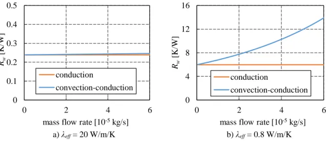
Figure I-42 : Thermal resistance as a function of the mass flow rate (ew = 6 mm, Sw = 12.5 cm²) ... 64
Figure I-43: Schematic of the pore geometry used by Zhao and Liao [108] ... 65
Figure I-44 : Heat transfer coefficient versus heat flux density (Zhao and Liao [108]) ... 66
Figure I-45 : Schematic of the vapour zone by Demidov and Yatsenko [138] ... 66
Figure I-46 : Schematic of the model developed by Figus et al. [114] ... 67
Figure I-47 : Example of results obtained by Figus et al. [114] ... 67
Figure I-48 : Pore network representation of porous microstructure (Mottet et al. [29]) ... 68
Figure I-49 : Schematic of discrete liquid-vapour interfaces in the pore network (Mottet et al. [29]) . 68 Figure I-50 : Development of a two-phase zone under the evaporator fins (Mottet et al. [29]) ... 69
Figure I-51: Schematic of the modelled LHP (a) and the nodal network (b): Siedel et al. [4], [141] ... 70
Figure I-52: Schematic of the 2D analytical model domain (Siedel [4]) ... 71
Figure I-53 : Influence of λeff on Te (adapted from Siedel [4]) ... 71
Figure I-54: Influence of λeff on the heat flux distribution if Qin = 50 W (Siedel [4]) ... 72
Figure II-1: Schematic of the complete LHP ... 74
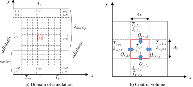
Figure II-2: Schematic of the 2D analytical model domain ... 74
Figure II-3 : Solving procedure of the model ... 77
Figure II-4: Results of the analytical model in standard conditions (Table II-3) ... 78
Figure II-5: Schematic of the discretization ... 80
Figure II-6: Example of temperature field inside the wick in a case of a valid isothermal boundary condition ... 81
Figure II-7: Example of temperature field inside the wick in the case of a non-valid isothermal boundary condition ... 81
Figure II-8: Evolution of the pressures inside the porous medium (Qin = 50 W, rp,top = 25 µm) ... 83
Figure II-9 : Evolution of the pressures inside the porous medium (Qin = 100 W, rp, top = 25 µm) ... 83
Figure II-10 : Influence of top layer thickness and thermal conductivity on the global thermal resistance ... 84
Figure II-11: Influence of the top layer thickness and thermal conductivity on the operating limits ... 85
Figure II-13 : Influence of the bottom layer thickness and thermal conductivity on the global thermal resistance ... 85
Figure II-12: Schematic of the heat transfer in the bottom layer between the evaporator fins and the fluid ... 86
Figure II-14: Influence of the bottom layer thickness and thermal conductivity on the operating limits
... 86
Figure II-15: Influence of the bottom and top layer permeability on the thermal resistance ... 87
Figure II-16 : Influence of the bottom and top layer permeability on the operating limits ... 87
Figure II-17 : Influence of the porosity on the global thermal resistance ... 88
Figure II-18: Influence of the bottom and top layer porosity on the operating limits ... 88
Figure II-19: Influence of the top and bottom layer pore radius on the thermal resistance... 89
Figure II-20 : Influence of versus the top layer pore radius on the operating limits ... 89
Figure II-21 : Influence of the bottom layer pore radius on the operating limits ... 90
Figure II-22 : Influence of the working fluid on the global thermal resistance ... 90
Figure III-1 : Competition between two mechanisms : Sintering and grain growth (adapted from Bernache-Assolant [146]) ... 94
Figure III-2 : Schematic of the wick before (left) and after the sintering (right), Déjou [147] ... 95
Figure III-3 : Schematic of Spark Plasma Sintering (Khor et al. [148]), illustrated on hollow spheres random compacts. ... 96
Figure III-4 : Distribution of the powder particles in the green compact (a) and interconnected porosity formed in the sintered wick (Samanta et al. [152]) ... 97
Figure III-5 : Pore radius (rp) of experimental LHP wicks versus the powder radius (rs) ... 98
Figure III-6: Evolution of the porosity of nickel samples as a function of the sintering temperature ... 98
Figure III-7 : Schematic of a freeze casting system (Wegst et al. [156]) ... 100
Figure III-8 : Schematic diagram of the ice templating process (adapted from Bouville [157]) ... 100
Figure III-9 : Cross sectional of ice templated ceramic samples including various additives (Bouville [157]) ... 101
Figure III-10 : Schematic of robocasting technique (Saiz et al. [162]) ... 102
Figure III-11 : Typical processing methods for the production of macroporous ceramics ... 103
Figure III-12: Pictures of the porous structure after PECS ... 104
Figure III-13: Particle size distribution of the copper power used for sintering ... 104
Figure III-14: Schematic of the method to obtain a flat disk shaped porous copper ... 105
Figure III-15: Temperature profile of the muffle furnace during the copper powder sintering ... 105
Figure III-16: Picture of the bottom layer (a) and XRD scan (b) ... 106
Figure III-17: Picture of a failed sintering process ... 106
Figure III-18: Particle size distribution of the zirconia powder ... 108
Figure III-19: Schematic of the freeze caster ... 108
Figure III-20: Example of pressure and temperature profiles used for freeze casting ... 109
Figure III-21: SEM pictures of a freeze casted samples ... 109
Figure III-22: Temperature profile of the muffle furnace during the zirconia powder sintering ... 110
Figure III-23: SEM pictures of the sample Zi-sin-5-a ... 111
Figure III-24: Pore size distribution of the nylon powder ... 111
Figure III-25: Schematic of the method to obtain a bi-layer wick ... 112
Figure III-26: Schematic arrangement of the gas ion and evaporation sources in a vacuum chamber 113 Figure III-27: Examples of topography analysis by confocal microscopy (profile (a, d) and complete surface (b, e)) and with pressure paper (c, f) of the side A of sample Cu-sin-7-c (a, b, c) and the side B of sample Cu-sin-2-c (d, e, f) ... 115
Figure III-28: XRCT of the sample Ni-sin-x (a) and microscopy of the sample Cu-sin-3-a (b) ... 115
Figure III-29: XRCT of a porous sample with large pores (2D and 3D views of the sample Ni-sin-x) ... 116
Figure IV-1: Experimental apparatus to measure the permeability using a constant pressure reservoir
(Singh et al. [169]) ... 120
Figure IV-2: Experimental set up to measure the permeability by NMR (Looyestijn et al. [170]) .... 121
Figure IV-3 : Schematic of the test benches for effective pore radius measurements (Holley and Faghri [171]) ... 121
Figure IV-4: Experimental apparatus designed to perform the bubble point testing (Singh et al. [7]) 122 Figure IV-5: U-tube bubble point testing system (Singh et al. [169]) ... 123
Figure IV-6: Schematic of the experimental setup ... 124
Figure IV-7: Schematic of the experimental procedure used to saturate the wick with liquid ... 124
Figure IV-8 : Schematic of the successive steps enabling to measure the permeability ... 125
Figure IV-9: Example of experimental data enabling to determine the permeability (Cu-sin-7-c) .... 126
Figure IV-10: Comparison between the permeabilities measured with pentane and with water ... 127
Figure IV-11 : Schematic of the successive steps enabling to measure the effective pore radius ... 127
Figure IV-12: Example of minimum meniscus radius determination (sample Cu-sin-5-a). ... 128
Figure IV-13: Contact angle of water (a) and pentane (b) on oxidised copper, and water (c) and pentane on standard copper (c) ... 129
Figure IV-14: Hydrodynamic characteristics of samples obtained with the same protocol ... 130
Figure IV-15: Porosity and mechanical resistance of the zirconia samples as a function of the percentage of PFA ... 133
Figure IV-16: Experimental permeability versus theoretical permeability calculated with the Kozeny-Carman and Rumpf-Gupte correlations... 135
Figure V-1 : Schematic of the experimental set up used by Zhao and Liao ([38], [108]) ... 138
Figure V-2: Schematic of the experimental set up used by Khammar et al. [110] ... 139
Figure V-3: Schematic of the experimental apparatus used by Delil and Baturkin [109] ... 139
Figure V-4 : Evolution of the vapour zone up to the breakthrough (Mottet et al. [29]) ... 140
Figure V-5 : Schematic of the experimental apparatus ... 141
Figure V-6 : Evaporator design (Siedel [4]) ... 141
Figure V-7: Example of thermal behaviour (sample Cu-sin4-a, water, 50 °C) ... 143
Figure V-8: Evaporator superheat in the presence (a) and in the absence (b) of a hysteresis (Cu-sin-2-c) ... 143
Figure V-9: Schematic of the meniscus motion depending on the heat load ... 144
Figure V-10: Test of reproducibility on the sample Cu-sin-5-a (water, Tsat = 50 °C) ... 146
Figure V-11: Influence of the saturation temperature on the thermal performance (Cu-sin-3-a, water) ... 147
Figure V-12: Influence of the hydrostatic pressure with sample Cu-sin-3-a (water, Tsat =50 °C) ... 148
Figure V-13: Influence of the chemical surface quality of the evaporator with sample Cu-sin-6-c (water, Tsat =50 °C) ... 149
Figure V-14: Influence of the pressure applied on the back face of the evaporator (sample Cu-sin-4-a, pentane, Tsat = 40 °C)... 149
Figure V-15: Heat transfer coefficient as a function of the heat load applied to a bi-layer wick as well as to the copper layer alone ... 150
Figure V-16: Confocal microscopy of the sample Cu-sin-7-c ... 152
Figure V-17: Influence of the surface quality on the thermal performance ... 153
Figure V-18: Schematic of the different contact configurations between the porous wick and the evaporator wall ... 154
Figure V-19: Schematic of the boiling dynamics at the vicinity of an evaporator fin ... 154
Figure V-20: Comparison of the thermal performance before and after the coating ... 155
Figure V-22: Qopt,exp as a function of Qopt,th with water ... 157
Figure V-23: ΔTsh,max,exp as a function of ΔTsh,max,th with water (rn = 3.6 µm) ... 158
Figure V-24: Pictures obtained with optical microscopy ... 158
Figure V-25: Heat transfer coefficient as a function of the heat load for each sample with pentane .. 159
Figure V-26: Qopt,exp as a function of Qopt,th with pentane ... 160
Figure V-27: Experimental maximum superheat as a function of the effective pore radius ... 160
Figure V-28: Comparison of the thermal performance of the samples with water and pentane ... 161
Figure V-29: Decision tree enabling the prediction of the heat transfer coefficient ... 164
Figure V-30: Decision tree enabling the prediction of the heat transfer coefficient with water ... 165
Figure A-1: Effective thermal conductivities calculated with λl = 0.6 W/m.K and λmat = 380 W/m.K 180 Figure B-1: Schematic of the 2D analytical model domain and boundary conditions ... 181
Figure B-2: Geometrical parameters enabling the resolution of the analytical model ... 182
List of tables
Table I-1 : Classification of the condenser technologies (adapted from Launay and Vallée [18]) ... 33
Table I-2: Analytical expressions of the operating temperature, Launay et al. [5] ... 38
Table I-3: Operating temperature range for various working fluids (Faghri [42]) ... 41
Table I-4: Environmental and safety properties of various working fluids ... 41
Table I-5: Properties of usual working fluids at 20 °C ... 42
Table I-6: Advantages and drawbacks of metallic wicks ... 46
Table I-7 : Advantages and drawbacks of polymer wicks... 47
Table I-8: Advantages and drawbacks of ceramic wicks ... 47
Table I-9 : Chemical compatibility between various fluids and materials ... 48
Table I-10: Studies investigating the wettability of water on various materials ... 50
Table I-11: Thermal characterisation of porous structures ... 55
Table I-12 : Comparison of porous samples permeabilities (Chen et al. [123]) ... 60
Table I-13: Characteristics of the LHP for the parametric study performed by Siedel [4] ... 70
Table II-1 : Nodal network equations of Siedel [4] and the present model ... 75
Table II-2: Output data of the model ... 76
Table II-3 : Definition of the standard LHP for the parametric study ... 78
Table II-4 : Maximum heat loads of various working fluids ... 91
Table II-5 : Optimum wick characteristics ... 91
Table III-1 : Effect of the sintering parameters on the wick characteristics. A “plus”, for positive, means that the effect corresponds to the objective of the manufacturer (high porosity and small pore radius) 99 Table III-2: Sintering parameters of the design of experiment ... 107
Table III-3: Manufacturing protocols of the copper samples obtained by sintering ... 107
Table III-4: Manufacturing protocols by freeze casting ... 110
Table III-5: Manufacturing protocols of zirconia samples by sintering ... 111
Table IV-1: Hydrodynamic characteristics of the manufactured samples... 131
Table IV-2: Influence of the sintering parameters on the wick characteristics ... 132
Table IV-3: Hydrodynamic characteristics of the zirconia samples ... 133
Table V-1: Influence of the saturation temperature on the theoretical limits (Cu-sin-3-a, water) ... 147
Table V-2: Results of thermal characterisation of the bilayer wick, and the copper layer alone (water, Tsat = 50 °C, Hl = 3.9 cm) ... 150
Table V-3: Surface quality of the samples manufactured following the design of experiment ... 151
Table V-4: Characteristics of the sample Cu-sin-7-c after each surface treatment (pentane, Tsat = 40 °C, Hl = 3.9 cm) ... 153
Table V-5: Results of characterisation of the two zirconia samples used to test the coating ... 155
Table V-6: Results of thermal characterisation with water (Tsat = 50 °C, Hl = 3.9 cm, side A) ... 157
Table V-7: Results of thermal characterisation with pentane (Tsat = 40 °C, Hl = 3.9 cm, side A) ... 159
Table V-8: Test parameters enabling the estimation of the heat transfer coefficient ... 163
Table B-1: kn coefficients (Siedel [4]) ... 182
Table C-1: Comparison between the porosity and permeability obtained with mercury intrusion and with the test benches used in this thesis ... 185
Nomenclature
Latin symbols
a, a0, a1 length (kn coefficients, Appendix B) m
aev accommodation coefficient -
b length (kn coefficients, Appendix B) m
B length ratio (kn coefficients, Appendix B) -
c, c0, c1 length (kn coefficients, Appendix B) m
C length ratio (kn coefficients, Appendix B) -
cp specific heat J.kg-1.K-1
d, d0 length (kn coefficients, Appendix B) m
D length ratio (kn coefficients, Appendix B) -
d diameter m
e thickness m
g specific free energy J/kg
g gravitational acceleration m.s-2
H height m
h heat transfer coefficient W.m-2.K-1
hlv enthalpy of vaporisation J.kg-1
I electrical current A
i, j finite element increment
J mechanical equivalent of heat kg.m.kcal-1
kn nth analytical model coefficient -
khfs heat flux sensor sensitivity
K permeability m²
L length m
l width m
m, n Fourier series increment (kn coefficients, Appendix B)
M, N line and column numbers of the discretisation matrix
𝑀̅ molar mass kg.mol-1
m mass kg
𝑚̇ mass flow rate kg.s-1
n iteration increment -
Nb Number of merit -
P pressure Pa
Q heat flux W
R thermal resistance K.W-1
𝑅̅ universal gas constant J.K-1.mol-1
r radius m
S cross-sectional area, or surface m²
t time s
U voltage V
u velocity m.s-1
𝑉̇ volumetric flow rate m3.s-1
V volume m3
x,y,z axis coordinates m
Greek Symbols
α regular pressure losses coefficient -
β singular pressure losses coefficient -
Δ difference -
δ film thickness
ε porosity -
λ thermal conductivity W.m-1.K-1
μ dynamic viscosity Pa.s
η pore depth (Zhao and Liao [107]) m
ϕ heat flux density W.m-2
ρ density kg.m-3 σ surface tension N.m-1 θ angle rad τ constant of time s 𝜉 tortuosity -
Subscripts
0 initial 2φ two-phase δ thin film∞ infinity, at the very end of the experiment
a advancing
amb ambient
b evaporator body
bot bottom layer
c condenser, condensation ci cumulative intrusion cont contact cap capillary Darcy Darcy e evaporator
eff effective elec electrical eq equilibrium ev evaporation exp experimental ext external f forming fin fins gap gap gr vapour grooves
hfs heat flux sensor
hl heat leaks
hs hydrostatic
i, j control volume increment
i inner, inlet, internal
in input
interconnection interconnection
L liquid line
l liquid
loss heat losses by the back face of the evaporator
LHP loop heat pipe
m meniscus mat material min minimum max maximum n nucleation NCG non-condensable gases o outer, outlet opt optimum p pore
p plate (only when associated with θ)
pentane pentane
r reservoir of the LHP
r receding (only when associated with θ)
res reservoir of the test bench
real real
s powder particle
s static (only when associated with θ)
sat saturation
sen sensible
sin sintering
sink heat sink
straight straight
sub subcooling
th theoretical
top top layer
tot total tube tube V vapour line v vapour vt vapour tube w wick water water
wall evaporator wall
wp pore wall
we wick, evaporator side
Non Dimensional Numbers
𝐵𝑖 =𝐿ℎ 𝜆 Biot number 𝑅𝑒 =𝜌𝑢𝑑 𝜇 Reynolds number 𝑃𝑒 =𝜌𝑢𝐿𝑐𝑝 𝜆 Peclet number
Introduction
The thermal management takes more and more place in many industrial sectors, especially in the telecom and computer industries (hardware), where the density of electronic components increases constantly. In 1965, Gordon Moore predicted (first Moore’s Law [1]) the every year doubling in the number of components per integrated circuit during a decade. In 1975, he readjusted his forecast (second Moore’s law [2]), saying that the number of transistors on a microprocessor will double every two year (Figure 0-1). This prediction has been verified up to 2010 where constructors faced cooling problems. The simultaneous power increase of computers and their dimension decrease leads to heat flux densities never encountered before. Moreover, the size of the classical cooling systems using a finned heat sink and a fan must be reduced and thus, the cooling capacity decreases as well.
Figure 0-1 : Microprocessor transistor counts between 1971 and 2011 and Second Moore’s law [2]
Thus, more performant cooling systems, usually based on liquid-vapour phase change phenomena, must be developed to answer these issues. Some of these devices use heat pipe technologies to transfer the heat from a very confined space to a location where space is available for the heat sink.
A heat pipe is a close tight envelope filled with a two-phase fluid at liquid-vapour equilibrium (Figure 0-2). The heat flux supplied at one end, called evaporator, enables to evaporate the liquid phase. The vapour flows to the other end, which is cooled and where it condenses. A capillary structure pumps the liquid back to the evaporator. Thus, this system is passive since there is no mechanical pump to ensure the circulation of the fluid. The absence of pump is a major advantage since it decreases the mass, the system complexity and the failure risk (less vibrations).
Figure 0-2 : Schematic of a capillary heat pipe (Bonjour et al. [3]).
However, heat flux densities transferred by traditional capillary heat pipes are generally limited, especially over long distances, due to operating limits inherent to the presence of a wick covering the whole internal surface of the device. Loop heat pipes (LHPs) are less sensible to this limit. A LHP operates similarly to a classic heat pipe. The main difference is that the wick is only located in the evaporator region (Figure 0-3). Furthermore, the vapour and the liquid lines are separated, avoiding the interactions between both phases that flow in opposite directions.
Figure 0-3 : Schematic of a loop heat pipe, Siedel [4]
The first LHP was developed to cool electronic components in spatial applications. Nowadays, two-phase loops are already implemented in industrial systems and especially the Capillary Pumped Loop for Integrated Power (CPLIP) whose operating principle is the same than in a LHP. They are used to evacuate the heat generated by railway inverters. Even if LHPs start to be commercialised, the physical mechanisms governing their operation are not fully understood and many researchers work on the improvement of their thermal performance. The CETHIL laboratory is involved in this research area for a dozen of years. In 2006, during the European project COSEE2, Launay et al. [5] developed a simplified analytical model in order to facilitate the design of LHPs. In 2010, the laboratory worked together with the ATHERM Company, in the framework of the SYSHANG3 project to manufacture the first LHP dedicated to avionic applications. Hodot [6] tested the thermal behaviour of this LHP submitted to an acceleration field. More recently, in the framework of the PRIMAE4 project, the CETHIL patented an
2COSEE: Cooling Of Seat Electronic box and cabin Equipment, European FP6-Project AST5-CT-2006-030800
3SYSHANG: SYStème à cHANGement de phase
4PRIMAE: Packaging of futuRe Integrated ModulAr Electronics, European Commission Grant Agreement FP7-265416-Primae – www.primae.org
adsorption-based antifreeze solution enabling a LHP to operate with water as the working fluid. During his PhD thesis, Siedel [4] developed a complete analytical model to accurately predict the heat and mass transfer inside a LHP.
However, since visual observation inside the evaporator of a LHP is difficult, the fine comprehension of the phenomena acting in its capillary structure remains nowadays an issue. Moreover, these phenomena are strongly coupled to those operating in the other parts of the loop. Thus, there is a need of experimental test benches decoupling the evaporator from the rest of the loop and enabling the analysis of its hydrodynamic and thermal behaviours.
The performance of the evaporator is closely linked to the wick characteristics, depending itself on its manufacturing process. Thus, the design and manufacturing of porous materials suitable for LHPs requires a collaborative work between material science and thermal science laboratories. The specific development of manufacturing procedures, using classical techniques like sintering or non-classical techniques like freeze casting or robocasting, is expected to enhance the heat transfer capacity of the LHPs. Thereby, the CETHIL laboratory and the MATEIS laboratory joined forces to build the 2MATHER5 project, which was funded by the Carnot Institute “Ingéniere @ Lyon” in 2015.
The present PhD thesis, which is part of this project, intends developing manufacturing techniques of capillary structures specifically dedicated to LHP applications. It also aims to better understand the link between the manufacturing parameters and the wick characteristics. An original approach, presented in Figure 0-4, will be developed to reach these objectives.
In a first step, the search of optimum wick characteristics will be undertaken, using a refined model describing the heat and mass transfer inside the LHP evaporator, coupled to a complete model of the system that provide realistic boundary conditions. In a second step, classical manufacturing techniques of porous materials (sintering) will be adapted to obtain the required characteristics while specific manufacturing methods (freeze casting) will be developed. The consecutive characterisation of the manufactured porous samples will highlight the effect of manufacturing parameters on these characteristics, and thus, helps to adjust these parameters and to improve the theoretical model. The in-situ testing of a capillary structure inside a LHP is the last step of this approach, but it is outside the scope of the present work.
Figure 0-4: Expected flowchart of the PhD thesis
52MATHER: MAtériaux poreux structures pour le MAnagement THERmique Theoretical
study Manufacturing
Hydrodynamic/Thermal
This thesis is organised as follows:
The Chapter 1 aims at providing the fundamental concepts of the physics involved in a LHP. It describes its operating principle, especially inside the capillary structure, and models describing the operation of a LHP evaporator are detailed.
The Chapter 2 presents the model used in the present study in order to understand the influence of various types of capillary structures dedicated to LHPs. An extensive parametric analysis is conducted to find the optimum characteristics of the porous medium.
The Chapter 3 proposes a state-of-the-art of the methods enabling to manufacture a porous medium. Then, it details the manufacturing processes used in this thesis: partial sintering, freeze casting and coating. It describes the characterisation of the capillary structures in terms of geometry, surface quality and pores architecture.
The Chapter 4 deeply investigates various test benches found in the literature enabling to characterise the hydrodynamic behaviour of porous samples. It justifies the choice of an experimental apparatus specifically dedicated to this study. The experimental set up enabling to determine the permeability and the effective pore radius of porous samples is described in this chapter. The results are discussed in terms of reproducibility and compared to the literature. Moreover, the influence of the manufacturing parameters on the hydrodynamic characteristics is investigated.
The Chapter 5 proposes a state-of-the-art of various test benches intended to investigate the heat and mass transfer in LHP evaporators. It enables the manufacturing of an experimental apparatus specifically designed to answer the objectives of this thesis. The influence of the capillary structure characteristics on the heat transfer coefficient and the operating limits is investigated. The results are discussed in a way to understand the physical mechanisms acting inside the porous structure.
Chapter I Introduction to the fundamental concepts of
the heat and mass transfer in a LHP
This chapter aims at providing the necessary background to understand the motivations of the present thesis. The fundamental concepts of the fluid flow and two-phase heat transfer in a capillary structure integrated in the environment of a LHP evaporator are presented, based on a literature study covering the experimental as well as the theoretical works performed by scientists in the field of LHPs.
In a first part, the operating principle of a LHP is summarised and its various components are described. Methods enabling to characterise the global performance of a LHP are presented. The types of fluids and wicks generally used in these devices are detailed, as well as the criteria leading to the selection of a fluid / wick material couple.
In a second part, an emphasis is put on the capillary structure. Since it is a key component of LHPs its characteristics have a significant influence on the operating limits and on the thermal performance of the system.
Finally, various models predicting the thermo-hydraulic behaviour of a porous medium, a wick/evaporator and a complete LHP are presented.
I.1
Description of a loop heat pipe and its operating principle
In this section, the LHP components and operating principles are thoroughly described in order to give a better understanding of the environment in which the capillary structures that will be manufactured and characterised throughout this PhD work are studied. Indeed, the physical phenomena occurring inside the wick are strongly coupled to the whole system operation.
A LHP is a closed tight device using liquid-vapour phase change to transfer high heat fluxes from a heat source to a heat sink with small temperature differences. The working fluid, at liquid-vapour equilibrium state, evaporates in the evaporator where a heat load is applied. Then, it flows through the vapour line to the condenser where it goes back to liquid state. The liquid flows back to the evaporator through the liquid line. The pumping force is provided by a wick located in the evaporator. Contrarily to thermosiphons and flat heat pipes, the vapour phase and the liquid phase are not in the same channel (Figure I-1). Thus, at high heat fluxes, the LHP is less concerned by interactions between the liquid phase flow and the vapour phase flow than a classic heat pipe where there is a unique channel (Singh et al. [7]).
Figure I-1 : Schematic of a classic LHP (Siedel et al. [8])
I.1.1 Description of the components of a LHP
A typical LHP includes four main components: the evaporator, the reservoir or compensation chamber, the transport lines and the condenser. A short description of each one and an explanation of their operating principles is provided hereafter. For more information about the components, the reader can refer to the works of Singh et al. [7], Ku [9], Maydanik [10] and Siedel [4].
I.1.1.1 Description of the evaporator / reservoir
The evaporator/reservoir is the key component of a LHP. Contrarily to a capillary pumped loop (CPL), in which the reservoir is connected to the liquid line (Figure I-2, b), the LHP has a reservoir integrated into the evaporator casing (Figure I-2, a). This casing can be flat shaped (Figure I-3) or of cylindrical design (Figure I-4), depending on the application and the operating pressure. It includes a wick, in closed contact to the internal wall and a set of vapour grooves that can be arranged inside either the casing or the wick. Various groove designs have been proposed in order to decrease the thermal resistance in the evaporator, for example by Singh et al. [7], Kaya and Goldak [11] or Altman et al. [12].
The reservoir, filled by the returning subcooled liquid, absorbs the variation of liquid volume inside the LHP when submitted to variable operating conditions. In a flat evaporator, the reservoir is usually located above the wick so that the liquid can directly percolate through it. In a cylindrical evaporator, the primary wick, designed of the shape of a hollow cylinder, is often fed by a concentric secondary
wick occupying all the evaporator/reservoir length. The liquid flows through the wick, which acts as a capillary pump. It evaporates at the contact of the wick with the internal casing, heated by the external heat source. The vapour is removed through the vapour grooves to the vapour line.
Figure I-2 : schematic of a LHP (a) and a CPL (b), Butler et al. [13]
Figure I-3 : Schematic of a flat evaporator (adapted from Singh et al. [14])
Figure I-4 : Schematic of a cylindrical evaporator (adapted from Kaya and Goldak [11]) Liquid Liquid line Liquid inlet Vapour outlet Qin Vapour line Reservoir Wick Transersal heat leaks Longitudinal heat leaks Evaporator Fin Casing Vapour groove Wick Core Liquid inlet Vapour outlet Qin
Radial heat leaks
Liquid inlet Vapour outlet
Axial heat leaks
The evaporator must transfer the largest possible part of the applied heat load Qin to the working fluid
in order to evaporate it. The heat not transferred to the fluid is called heat leak or parasitic heat flux (Figure I-3 and Figure I-4). The parasitic heat flux goes to the reservoir through different ways. The heat leaks going from the evaporator to the reservoir through the wick are called transversal or radial heat leaks for a flat or a cylindrical evaporator respectively. The heat leaks going from the evaporator to the reservoir through the evaporator casing are called longitudinal or axial heat leaks for a flat or a cylindrical evaporator respectively.
The heat leaks help the LHP to start up, by heating the fluid located in the reservoir when the heat load is applied. This is the major advantage of a LHP compared to a CPL, which requires the pre-heating of the compensation chamber before the start-up. However, after the start-up stage, the heat leaks must be as low as possible. Indeed, they decrease the performance of the system by increasing the reservoir temperature. According to Wang et al. [15], the flat evaporator enables a better contact between the wick and the evaporator due to the flat interface. However, it suffers from more heat leaks.
When the fluid evaporates, an interface between the vapour and liquid phases is created in the wick (Figure I-5). The curvature of this interface leads to a pressure difference between the vapour and the liquid. This phenomenon is described by the Young-Laplace equation:
Δ𝑃𝑐𝑎𝑝= 𝑃𝑣− 𝑃𝑙 =
2𝜎
𝑟𝑚 (I-1)
where ΔPcap is the capillary pressure, Pv the vapour pressure, Pl the liquid pressure, the surface tension
of the working fluid, rm the meniscus radius of curvature.
The capillary pressure acts as a pump and enables the working fluid to circulate around the loop by compensating the pressure losses. When the heat load increases, the pressure losses increase and the meniscus radius decreases to keep an equilibrium.
In the case of a cylindrical evaporator, the wick may include two different structures: the primary and the secondary wicks (Figure I-5). The role of the secondary wick is to bring the working fluid to the primary wick and to avoid a local dry out. It has to be sufficiently permeable to spread the fluid in the primary wick, whereas the latter should have small pores to provide a high capillary pressure.
In most of the cylindrical LHP designs, a bayonet extends the liquid line to feed the end of the evaporator core opposite to the reservoir with cold liquid, avoiding the occurrence of superheated regions (Figure I-5). The role of the bayonet is more deeply analysed by Hodot [6] and Soler [16].
![Figure 0-1 : Microprocessor transistor counts between 1971 and 2011 and Second Moore’s law [2]](https://thumb-eu.123doks.com/thumbv2/123doknet/14691492.745431/26.892.239.684.432.812/figure-microprocessor-transistor-counts-second-moore-s-law.webp)
![Figure I-16 : Thermal expansion coefficients of various polymers, metals and ceramics (Lide [46])](https://thumb-eu.123doks.com/thumbv2/123doknet/14691492.745431/46.892.115.777.228.548/figure-thermal-expansion-coefficients-various-polymers-metals-ceramics.webp)
![Figure I-26 : Evolution of the evaporator heat transfer coefficient as a function of the heat flux density and the saturation temperature (Zhao and Liao [38])](https://thumb-eu.123doks.com/thumbv2/123doknet/14691492.745431/55.892.242.667.573.897/figure-evolution-evaporator-transfer-coefficient-function-saturation-temperature.webp)