HAL Id: tel-03152789
https://tel.archives-ouvertes.fr/tel-03152789
Submitted on 25 Feb 2021
HAL is a multi-disciplinary open access archive for the deposit and dissemination of sci-entific research documents, whether they are pub-lished or not. The documents may come from teaching and research institutions in France or abroad, or from public or private research centers.
L’archive ouverte pluridisciplinaire HAL, est destinée au dépôt et à la diffusion de documents scientifiques de niveau recherche, publiés ou non, émanant des établissements d’enseignement et de recherche français ou étrangers, des laboratoires publics ou privés.
images into synthetic DNA
Dimopoulou Melpomeni
To cite this version:
Dimopoulou Melpomeni. Encoding techniques for long-term storage of digital images into synthetic DNA. Computer Science [cs]. Université Côte d’Azur, CNRS, I3S, France, 2020. English. �tel-03152789�
Techniques de codage pour le stockage à long terme
d’images numériques dans l’ADN synthétique
Melpomeni Panagiota DIMOPOULOU
Laboratoire d’Informatique, Signaux et Systèmes de Sophia-Antipolis (I3S)
Présenté en vue de l’obtention Devant le jury, composé de :
du grade docteur enAutomatique Marc ANTONINI, Directeur de Recherche, CNRS
Traitement du Signal et des Images Raja APPUSWAMY, Professeur Assistant, EURECOM
d’Université Côte d’Azur Pascal BARBRY, Directeur de Recherche, CNRS
Dirigé par :Marc Antonini Frédéric DUFAUX, Directeur de Recherche, CNRS
Soutenue le :04/12/2020 Touradj EBRAHIMI, Professeur, EPFL
Christine GUILLEMOT, Directrice de Recherche, INRIA
Thomas HEINIS, Professeur Assistant, Imperial College London Emily LEPROUST, Directrice Generale, Twist Bioscience
iii
Techniques de codage pour le stockage à long terme
d’images numériques dans l’ADN synthétique
Jury:
Rapporteurs
Christine GUILLEMOT, Directrice de Recherche, Institut National de Recherche en Informatique et en Automatique (INRIA)
Thomas HEINIS, Professeur Assistant, Imperial College London
Examinateurs
Touradj EBRAHIMI, Professeur, École Polytechnique Fédérale de Lausanne (EPFL) Frédéric DUFAUX, Directeur de Recherche, CNRS, Université Paris-Sud
Emily LEPROUST, Directrice Generale, Twist Bioscience
Pascal BARBRY, Directeur de Recherche, CNRS, Université Côte d’Azur Raja APPUSWAMY, Professeur Assistant, EURECOM
v
Techniques de codage pour le stockage à long terme d’images
numériques dans l’ADN synthétique
Résumé
L’explosion de la quantité de données est l’un des plus grands défis de l’évolution numérique, entraînant une croissance de la demande de stockage à un rythme tel qu’elle ne peut pas rivaliser avec les capacités réelles des pé-riphériques. L’univers numérique devrait atteindre plus de 175 zettaoctets d’ici 2025, tandis que le 80% de ces données est rarement consultée (données froides), mais archivée sur des bandes magnétiques pour des raisons de sécu-rité et de conformité réglementaire. Les dispositifs de stockage convention-nels ont une durée de vie limitée de 10 à 20 ans et doivent donc être fréquem-ment remplacés pour garantir la fiabilité des données, un processus qui est coûteux en termes d’argent et d’énergie. L’ADN est un candidat très promet-teur pour l’archivage à long terme de données «froides» pendant des siècles voire plus à condition que l’information soit encodée dans un flux quater-naire constitué des symboles A, T, C, G, pour représenter les 4 composants de la molécule d’ADN, tout en respectant certaines contraintes d’encodage importantes. Dans cette thèse, nous présentons de nouvelles techniques de codage pour le stockage efficace d’images numériques dans l’ADN. Nous avons implémenté un nouvel algorithme de longueur fixe pour la construc-tion d’un code quaternaire robuste qui respecte les contraintes biologiques et proposé deux fonctions de "mapping" différentes pour permettre une flexi-bilité par rapport aux besoins d’encodage. De plus, l’un des principaux défis du stockage des données dans l’ADN étant le coût élevé de la synthèse, nous faisons une toute première tentative pour introduire une compression con-trôlée dans la solution de codage proposée. Le codec proposé est compétitif par rapport à l’état de l’art. En outre, notre solution de codage / décodage de bout en bout a été expérimentée dans une expérience de laboratoire humide pour prouver la faisabilité de l’étude théorique dans la pratique.
Mots clés: Stockage de données dans l’ADN, Codage d’images, ADN syn-thetique, Compression d’images, Codage robuste
vii
Encoding techniques for long-term storage of digital images
into synthetic DNA
Abstract
Data explosion is one of the greatest challenges of digital evolution, causing the storage demand to grow at such a rate that it cannot compete with the actual capabilities of devices. The digital universe is forecast to grow to over 175 zettabytes by 2025 while 80% is infrequently accessed (“cold” data), yet safely archived in off-line tape drives due to security and regulatory compli-ance reasons. At the same time, conventional storage devices have a limited lifespan of 10 to 20 years and therefore should be frequently replaced to en-sure data reliability, a process which is expensive both in terms of money and energy. Recent studies have shown that due to its biological properties, DNA is a very promising candidate for the long-term archiving of “cold” digital data for centuries or even longer under the condition that the information is encoded in a quaternary stream made up of the symbols A, T, C and G, to represent the 4 components of the DNA molecule, while also respecting some important encoding constraints. Pioneering works have proposed dif-ferent algorithms for DNA coding leaving room for further improvement. In this thesis we present some novel image coding techniques for the efficient storage of digital images into DNA. We implemented a novel fixed length al-gorithm for the construction of a robust quaternary code that respects the bi-ological constraints and proposed two different mapping functions to allow flexibility according to the encoding needs. Furthermore, one of the main challenges of DNA data storage being the expensive cost of DNA synthesis, we make a very first attempt to introduce controlled compression in the pro-posed encoding workflow. The, propro-posed codec is competitive compared to the state of the art. Furthermore, our end-to-end coding/decoding solution has been experimented in a wet lab experiment to prove feasibility of the theoretical study in practice.
Keywords: DNA data storage, Image coding, Synthetic DNA, Image com-pression, Robust encoding
“The true sign of intelligence is not knowledge, but imagination...”
ix
Acknowledgements
This thesis has been a great adventure for me and has helped me broaden my horizons and get to know the main aspects of research. However, nothing would have been possible without the help and guidance of my supervisor Dr. Marc Antonini who has been a great advisor, always present to guide me in any moment of doubt, encouraging me to take initiatives and feel free to express my ideas while also enlightening me with all his knowledge and experience! He has been my mentor and I couldn’t be more grateful to him as anything I have achieved in the field of research is due to his constant advice and the fact that he always believed in me, sometimes even more than I did myself!
Then, I would also like to thank Christine Guillemot and Thomas Heinis for accepting to review my thesis manuscript despite the amount of work this might require. I am also grateful to Touradj Ebrahimi, Emily Leproust and Frederic Dufaux who have accepted to take part in my PhD jury. I would like to separately express my gratitude to Raja Appuswamy and Pascal Barbry for their helpful comments and advise not only as members of my PhD jury but through-out our collaboration during the past three years.
Furthermore, I would like to thank all my colleagues in the lab (new ones and old ones) for their feedback, cooperation and of course friendship. But I would like to separately mention my closest friends in the lab: Somia, Vasilina, Diana, Ninad, Cyprien, Arnaud, Gaël and Froso, thank you for all the times you were there for me to celebrate the happy moments and to en-courage me during the most difficult times. A very big and special “Thank you” to my dear friend and academic alter-ego, Eva, with whom I have worked together for the last two years and she has supported me through all the difficult research moments.
In addition, I would like to express my sincere appreciation to the staff of the administration for their help and especially Nadia, our mother in the lab, for all her kindness and the last-minute favors.
At this point, I would also like to express my deep gratitude to my pro-fessors from the Computer Engineering and Informatics Department in the University of Patras in Greece, who played an important role in the construc-tion of a strong core of basic knowledge which has been the most helpful tool in the pursue of my academic career. More precisely, I would like to thank Emmanouil Psarakis, my bachelor thesis supervisor, for guiding me, inspir-ing me and motivatinspir-ing me to explore the field of Signal and Image process-ing. Then, I would also like to thank Kostas Berberidis for all the knowledge, fruitful discussions and his valuable advice when I was in doubt. And last but not least, I would like to thank the person to whom I owe the beginning of this wonderful journey in France, Evi Papaioannou, for all the help, the support and encouragement to accept the challenge and take this first step in following my dreams.
Throughout this exciting adventure, I also had the chance to be surrounded by some very special people who are always there for me even if we rarely meet due to the long distance... my best friends, Maria, Natassa, Penny, Ioanna and Vassilis. Thank you for always making my day with your posi-tive energy and encouragement along these years!
A big and very special “Thank you” goes to my family! First of all, my parents, to whom I owe everything I am today and are always by my side
filled with pride for any of my achievements, supporting all my efforts and constantly providing me with love, strength and courage, as well as my beloved sister Georgina for all her love and her continuous support since I moved to France. Also, I would like to separately thank my oldest, wisest and most wonderful professor I have ever had in my life since I was 6 years old... my grandfather Alekos, to whom I owe the biggest part of any of the knowledge I have today!
Finally, the most special thank you goes to Dimitris, my partner in life, with whom I have been sharing all my thoughts and fears and has always been supporting me through everything! I would like to thank him for his encouragement to the pursue of my dreams even if this required much more strength due to the long-distance of the first 2 years. Thank you for your patience during my complaints and all the moments we share every day.
xi
Contents
Acknowledgements ix
1 Introduction 1
1.1 Digital data storage . . . 1
1.1.1 Some statistics . . . 3
1.1.2 What is cold data? . . . 3
1.1.3 Problem definition . . . 4
1.1.4 Existing solutions . . . 4
1.2 What is DNA coding? . . . 5
1.2.1 Advantages . . . 5
1.2.2 The challenges . . . 7
1.3 Outline . . . 7
2 State of the art on DNA coding 11 2.1 General workflow . . . 11
2.1.1 The structure of DNA . . . 11
2.1.2 DNA synthesis . . . 13 2.1.3 DNA sequencing . . . 14 2.2 A constrained problem . . . 19 2.2.1 Encoding . . . 20 2.2.2 Decoding . . . 21 2.3 Existing works . . . 21
2.3.1 First references to the idea of DNA data storage . . . . 22
2.3.2 The first application of DNA data storage by Church et al. . . 22
2.3.3 First biologically constrained encoding by Goldman et al. 23 2.3.4 Introduction of Reed-Solomon codes by Grass et al. . . 23
2.3.5 First random-access implementation by Yazdi et al. . . 24
2.3.6 Reed Solomon codes on headers by Blawat et. al . . . . 25
2.3.7 DNA coding using Fountain codes by Erlich et al. . . . 26
2.3.8 Efficient end-to-end workflow by Microsoft researchers 27 2.4 Contributions of this work . . . 27
3 A novel constrained quaternary encoding 29 3.1 Introduction . . . 29
3.2 Creating a constrained DNA code - Our solution . . . 30
3.2.1 General Definitions . . . 30
3.2.2 Construction of the codewords (PAIRCODE) . . . 31
3.2.3 Discussion . . . 33
3.3 The proposed mapping algorithm for avoiding pattern repetition 35 3.3.1 The algorithm . . . 35
3.3.2 Discussion . . . 37
3.5 A controlled code-mapping resistant to sequencing noise . . . 41
3.5.1 Introduction to the proposed resistant to noise mapping 42 3.5.2 The proposed controlled mapping algorithm . . . 44
3.6 Proposed decoding of undecodable words . . . 46
3.6.1 Simple Correction Decoding (SCD) . . . 47
3.6.2 Advanced Correction Decoding (ACD) . . . 47
3.7 Experimental results . . . 49
3.8 Conclusion . . . 51
4 Design of a closed-loop DNA-based image coder 55 4.1 Introduction . . . 55
4.2 A novel image coding/decoding solution into synthetic DNA 56 4.3 Source Allocation . . . 57
4.4 Quantization . . . 59
4.4.1 Nucleotide allocation using Uniform Scalar Quantization 59 Nucleotide allocation using splines approximation . . 61
Nucleotide allocation using permutations . . . 62
4.4.2 Nucleotide allocation for Vector Quantization . . . 64
4.5 Conclusions . . . 66
5 A JPEG-based coding algorithm for DNA image storage 71 5.1 Introduction . . . 71
5.2 Theoretical background: The JPEG algorithm . . . 71
5.3 The proposed variable-length DNA coding algorithm . . . 73
5.4 Comparison of the different encoding solutions . . . 75
5.5 Conclusions . . . 78
6 Formatting the encoded data for oligo synthesis 81 6.1 Introduction . . . 81
6.2 The proposed formatting for the fixed length encoding . . . . 82
6.2.1 Formatting when using DWT and Uniform Scalar Quan-tizer . . . 83
6.2.2 Formatting when using DWT and Vector Quantization 84 6.2.3 Formatting when using VQ and controlled mapping . 86 6.3 The proposed formatting for the variable-length encoding . . 87
6.4 Barcodes . . . 89
6.4.1 Background and existing methods . . . 89
6.4.2 The algorithm for building error correcting barcode sets: discussion . . . 92
6.4.3 Our proposed barcoding algorithm . . . 93
6.5 Conclusions . . . 94
7 Wet lab experiment 97 7.1 Description of the experiment . . . 97
7.2 Encoding . . . 97
7.2.1 The general workflow . . . 97
7.2.2 Details on the encoding used for the experiment . . . . 98
7.3 DNA Synthesis and storage . . . 101
7.4 DNA sequencing and oligo selection . . . 102
7.5 Decoding . . . 103
xiii
7.7 Two years later... . . 106
7.8 Conclusions . . . 109
8 General conclusions and future steps 111 8.1 Conclusions . . . 111
8.2 Discussion . . . 112
8.3 Future work and perspectives . . . 113
A Algorithms 115 A.1 Section 1 . . . 115 B Training set 117 C Publications 119 C.1 Journals . . . 119 C.2 Conference papers . . . 119 C.3 Patents . . . 120 C.4 Awards . . . 120
xv
List of Figures
1.1 Hierarchy of data . . . 1
1.2 Byte Shipment . . . 2
1.3 The different types of storage according to data’s temperature 4 1.4 Comparison of DNA to other means of digital data storage . . 6
2.1 Main component parts of a typical DNA storage process. . . . 11
2.2 The structure of a DNA molecule . . . 13
2.3 The process of PCR explained . . . 14
2.4 The steps of a cycle of DNA synthesis . . . 15
2.5 Illumina flowcell . . . 16
2.6 Sequencing with illumina explained . . . 16
2.7 Illumina basecalling explained . . . 17
2.8 The Illumina sequencer . . . 18
2.9 Sequencing with Nanopore explained . . . 18
2.10 The Nanopore MinION sequencer . . . 19
2.11 Encoding of digital data into DNA. . . 20
2.12 Decoding of digital data stored into DNA. . . 21
2.13 Results of the study carried out by Church et. al. . . 23
2.14 Goldman et. al. encoding . . . 24
2.15 Grass et. al. encoding . . . 24
2.16 Blawat et. al. encoding. . . 25
2.17 Erlich et. al. encoding . . . 26
3.1 Encoding process of communication systems associated to DNA coding. . . 29
3.2 The A,T and G,C nucleotide percentage using PAIRCODE . . 31
3.3 Mapping of quantized values into quaternary code . . . 35
3.4 Mapping example with error-correction . . . 37
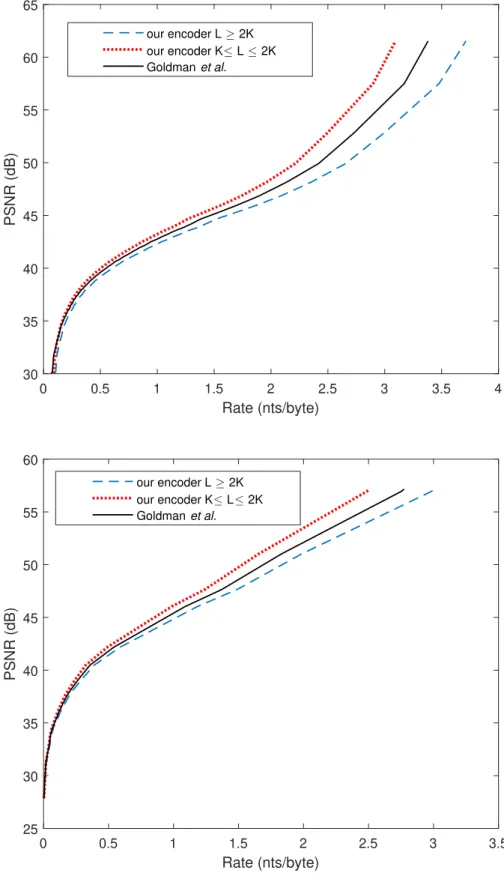
3.5 Comparison to the encoding algorithm of Goldman et. al. us-ing the curve of PSNR vs. Rate . . . 40
3.6 Example of a Hamming sphere. . . 43
3.7 An example of using a simple mapping vs. using a controlled noise resistant mapping for L=40. . . 44
3.8 The optimal mapping of vector indices to codewords accord-ing to the controlled noise-resistant mappaccord-ing . . . 46
3.9 The decoding grid after the first decoding step. . . 48
3.10 ACD decoding explained . . . 48
3.11 Controlled error-resistant mapping - PSNR improvement in function of the error rate for different cases of VQ parameters K and n . . . 52
3.13 Results of the use of controlled mapping algorithm vs. the use of simple mapping when applied to a workflow contain-ing DWT and Vector Quantization. For the encodcontain-ing we ap-ply a 3-level DWT and quantize each subband independently using Vector Quantization. We then map the quantized code-vectors to codewords of a code produced by our PAIRCODE algorithm using simple or controlled mapping. The encoded strands have been then corrupted by substitution noise inserted at the same positions of the strand. The figure depicts the im-pact of the error for the two different mapping cases. . . 54 4.1 Optimized Mapping of quantized values into quaternary code
for image coding application . . . 60 4.2 The general DNA encoding schema for image coding . . . 60 4.3 RD-curve of one subband sb as provided by the nucleotide
al-location using Scalar Quantization. . . 68 4.4 Results of nucleotide allocation using Scalar Quantizer (R-D
curve and visual quality) . . . 68 4.5 Exhaustive nucleotide allocation example of produced
point-cloud on the axis of PSNR in function of the Rate. . . 69 4.6 Coding/decoding workflow using Vector Quantization. . . 69
4.7 Example of an oligo encoded using VQ with pattern repetitions (top oligo) as well as avoiding pattern repetitions (bottom oligo) . . . 69
4.8 Behaviour of the rate-distortion curve in one wavelet subband when using VQ. . . 70 4.9 Comparison of the global rate-distortion curves for Vector
Quan-tization and Scalar QuanQuan-tization for a 512x512 image of Lena. 70 5.1 Block decomposition for JPEG . . . 72 5.2 Workflow of the JPEG standard . . . 73 5.3 Workflow of the modified JPEG workflow to suit the needs of
DNA coding . . . 75 5.4 Original image of cat which has been used in our experiment
of comparing the efficiency of the different encoding methods 76 5.5 Comparison of R-D curves produced by the different proposed
encoding solutions. . . 78 5.6 The impact of one deletion error on a 512x512 pixel image of
a cat for the different encoding solutions.The original images have been compressed to obtain the same Rate of 25.5 bits/nt. 79 5.7 The impact of one deletion error on a 512x512 pixel image of
a cat for the different encoding solutions. The original images have been compressed to obtain the same PSNR value of 38.5 dB. . . 80 6.1 General formatting of an oligo. . . 84 6.2 Proposed oligo formatting for a compression workflow that
uses a DWT and a Uniform Scalar Quantizer . . . 85 6.3 Proposed oligo formatting for a compression workflow that
uses a DWT and a Vector Quantizer . . . 87 6.4 Proposed oligo formatting for a compression workflow that
xvii
6.5 Proposed oligo formatting for a compression workflow that uses closed-loop JPEG for DNA coding . . . 88 6.6 An example where Levenshtein distance fails to capture a
dele-tion error. . . 91 7.1 The formatting used in the wet-lab experiment. . . 98 7.2 Nucleotide allocation curves used for the wet lab experiment
for the image of Lena and Mezzanine . . . 99 7.3 The two images selected for our wet-lab experiment. Figures a
and b show the original images whereas figures c and d depict the compressed versions which have been selected using the source allocation and have been stored into DNA. The PSNR values are computed with respect to the original images. . . . 100 7.4 Part of the real formatted oligos that have been synthesized
during our wet-lab experiment. . . 101 7.5 Left image: Pool of synthesized oligos produced by Twist
Bio-science. Right image: Capsules containing the synthesized DNA libraries. The capsules have been provided by Imagene company which is located in Evry in France. . . 102 7.6 Oligo pre-processing workflow . . . 103 7.7 Visual results of the reconstructed images provided by the
wet-lab experiment. . . 105 7.8 Visual results after decoding the image of Lena (128x128) at
different subsampling rates of the sequenced pool of oligos. . 106 7.9 The evolution PSNR and percentage of correct oligos for
dif-ferent sampling sizes . . . 107 7.10 Correct oligo reads in the sequencing experiment after two
years of storage. . . 108 7.11 Visual results of the decoding of the stored oligos two years
after storage. The figures correspond to two different cases of reconstruction: using the most frequent oligos (left column) and random selection (right column). For the left images the PSNR value is only due to the error inserted by the quantiza-tion process as we have managed to get a reconstrucquantiza-tion with-out any sequencing noise, For the right images (random selec-tion), both quantization and sequencing error appear. . . 109 B.1 VQ cat training set . . . 117
xix
List of Tables
3.1 Comparison between the PAIRCODE algorithm and the Ex-haustive code generation (for word length 2nt to 10nt). . . 34 3.2 Comparison of Our encoder with L ≥ 2K and our encoder
with K ≤ L ≤ 2K to Goldman et. al. [1] Here the rate is ex-pressed in bits per nucleotide (bits/nt) to highlight the coding potential of the different solutions. . . 39 3.3 Comparison to previous works - Coding potential: maximal
information content of each nucleotide before indexing or er-ror correcting. Redundancy: excess of synthesized oligos to provide robustness to dropouts. Error correction/ detection: the presence of error-correction code to handle synthesis and sequencing errors. Full recovery: DNA code was recovered without any error. Net information density: input information in bits divided by the number of synthesized DNA nucleotides (excluding primers). . . 39 5.1 Category range for encoding values using JPEG . . . 73 5.2 Category range for encoding values using DNA. Category 1
is omitted due to the biological constraints imposed by DNA sequencing. . . 75 6.1 Comparison of the number of barcodes produced by: The
bar-coding algorithm proposed in [2], our proposed barcoding al-gorithm applied to an exhaustive code which contains all pos-sible viable DNA codewords (similarly to [2]), and our pro-posed barcoding algorithm applied to a code constructed by PAIRCODE (see section 3.2.2). . . 94
xxi
List of Abbreviations
AC Alternating Current
ACD Advanced Correction Decoding
BA Bridge Amplification
DC Direct Current
DCT Discrete Cosine Transform
DNA DeoxyriboNucleic Acid
DPCM Differential Pulse Code Modulation
IDC International Data Corporation
DWT Discrete Wavelet Transform
JPEG Joint Photographic Experts Group
MSE Mean Square Error
NGS Next Generation Sequencing
nt nucleotide(s)
PCR Polymerase Chain Reaction
PSNR Peak Signal to Noise Ratio
SBS Sequencing By Synthesis
SCD Simple Correction Decoding
SQ Scalar Quatization
VQ Vector Quantization
xxiii
List of Symbols
asb Fraction of total pixels of a subband sb
B Set of barcodes
C Set of all possible quaternary words composed by the symbols{A, T, C, G} C∗ Constrained codebook provided by PAIRCODE
Cu Set of decodable codewords in the 1-ring neighborhood (space domain) of an
undecodable word
ce Erroneous codeword
D distortion
D Set of all possible viable quaternary words composed by the symbols{A, T, C, G}
dE Euclidean distance
dH Hamming distance
dL Levenshtein distance
dSL Sequence-Levenshtein distance
F(v) empirical function used to compute the density of the neighborhood of a vector v H(ck) Hamming sphere of ck containing words with Hamming distance of 1 to ck.
K number of indices in the codebook L number of codewords in the code l length of codewords in the code #` number of levels of DWT
m number of different codewords from code assigned to each source symbol n length of quantization vectors in VQ
PR Matrix of all possible permutations of subband rates providing a target total rate
PT Matrix of all possible permutations of subband rates
p(u) probability of a vector v
q Quantization step size of Uniform Scalar Quantizer
R Rate
S(vk) Neighborhood containing the closest vectors around vector vk
SB Number of subbands
V Set of input source symbols
VHu Set of vectors to which are mapped the codewords belonging to
Vu Set of vectors to which are mapped the codewords belonging to
the neighborhood around an undecodable word
vu Vectors belonging in the set VHu of vectors to which are mapped codewords from
the same Hamming sphere Hu.
W Set of undecodable codewords
wu undecodable word
α(vk) Function that provides the index k of vk
β trade-off parameter
Γ Mapping function
λ Lagrange multiplier (slope of the R-D curves)
νu Vectors belonging in the set Vu of vectors to which are mapped the codewords from
the same neighborhoodCu around some undecodable word wu.
φ(v) Summation of euclidean distances between a vector v and all vectors belonging
to its neighborhood
Σ Set of indices
xxv
1
Chapter 1
Introduction
1.1
Digital data storage
The problem of data explosion constitutes nowadays one of the greatest chal-lenges of digital evolution. The continuous greedy use of the internet, includ-ing digital platforms and social networks is leadinclud-ing to an immersive increase in the generation of digital data which needs to be handled and stored effi-ciently. This information overload is massively stored in the servers of big data centers where it is being organized and archived using different tech-nologies according to the data’s nature and demand. Data centers contain a set of routers and switches that transport traffic between the servers and to the outside world. To better understand the organization of the data into server systems, figure1.1illustrates the various parts of current memory and storage units.
Figure 1.1:Hierarchy of data
Data storage can be hierarchically divided in 6 different layers.
• The top layer consists of small-size processor registers which handle the data which is accessed very frequently in immediate term and therefore needs to be fast and efficient. This type of storage is power-on and small in capacity.
• The second layer contains cache processors which are acting as a tem-porary storage area where the processors of the top layer can retrieve
data from easily. This layer is also working power-on and it is small in capacity and fast in access time.
• The third layer is the last power-on part of the pyramid. It consists of the Random Access Memory (RAM) which contains short term data that can be read in any order, to retrieve information needed by the cache processors of the previous layer. RAM memory is medium capacity and fast in access time.
• The next layer consists of the flash storage which can work off-line and contains short term data. It is large in capacity but slower in access time. • The second power-off layer consists of the hard drives (HDD). It is used for mid term storage and contains data which is less frequently used and therefore it is slower in access time than flash storage. This type of memory has a large size and a large capacity.
• Finally, the last part of the pyramid concerns the data which is very infrequently accessed. This type of data can be stored in tape back-ups which are very slow in access time and very large in capacity.
It is easy to notice that the volume of data which is more frequently ac-cessed is extremely small compared to the data of less frequent demand. To this end, the last two layers of the hierarchy consist of solutions of a large capacity which unfortunately also exhibit a much larger volume.
An article published in Forbes magazine [3] mentions that according to International Data Corporation (IDC), 22 Zettabytes (ZB) of digital storage will be shipped across all storage media types between 2018 and 2025, with nearly 59% of that capacity supplied by the HDD industry. Figure1.2depicts the predicted exponential growth in the byte shipment for the different types of storage media. As can be seen, by 2025 there is expected to be significant amounts of digital stored in HDDs, in various solid state storage as well as magnetic tape.
Figure 1.2:Byte Shipment as reported in [3]
It is clear that this exponential growth in the generation of digital data should not be neglected and we are about to face some serious obstacles given the existing storage resources! In the next paragraph we will provide some interesting statistics that clearly expose the impact of this data explo-sion in many different aspects of our everyday life.
1.1. Digital data storage 3
1.1.1 Some statistics
According to an article published in [4], the rapid rise in smartphone usage, IoT adoption, and big data analytics have led to a massive growth in data centers, and they come with a cost. This article presents the following statis-tics as provided by IDC.
• In 2012 there existed 500.000 data centers to handle global traffic while today there exist more than 8 million.
• The yearly CO2 emissions of data centers reaches the amounts of CO2 produced by the global airline industry.
• Every year, millions of data centers worldwide are draining country-sized amounts of electricity. Several models even predict that data cen-ter energy-usage could engulf over 10% of the global electricity supply by 2030 if left unchecked.
• 90% of the existing data have been only generated in the last 2 years. • The amount of energy used by data centers continues to double every
four years.
Along with the above numbers, it is also known that storage media have a limited life-span which varies from 3-5 years for HDD drives and 20-30 years for back-up tape drives. To reassure reliability of the stored data, it is there-fore necessary that data centers frequently replace the different storage units, a fact that leads to a huge hardware waste. Furthermore, the replacement of older storage units yields the need for migrating the data into the new units, a process which is expensive both in terms of money and energy. All these facts, reveal that the enormous increase in the generation of data is causing important pollution to the environment. Due to the resulting environmental impact, increased pressure has been placed on companies to follow a green policy by building green or sustainable data centers which utilize energy-efficient technologies.
1.1.2 What is cold data?
For managing, storing and re-purposing digital content, industries and data centers differentiate the data into three levels, hot, warm and cold, based on interest or access priorities. The frequency of data demand (metaphorically called data temperature) denotes the most appropriate unit to which each type of data should be stored. More precisely, hot data refers to assets that require the fastest storage as they are accessed most frequently. It is thus stored in the nearest or closest spots from the accessing points such as solid state or flash drives and CPU. Warm data represents information that is less accessible and is stored on a bigger storage capacity or file servers for rel-atively cost-efficient concern. Finally, the data which is very rarely or even never accessed and doesn’t require on-line workflow is placed on the slow-est low-cost options of storage mediums such as tape and optical discs and is termed as cold data.
Figure 1.3 depicts the different levels of data temperature as well as the most appropriate means of storage according to the access frequency. It is
Figure 1.3:The different types of storage according to data’s temper-ature (image taken from [5].)
clear that the largest part of digital information consists of cold data and in spite of its infrequent use, this information must be nevertheless stored in back-up tape drives due to security and regulatory compliance reasons. Old photographs stored by users on Facebook is one such example of cold data; Facebook recently built an entire data center dedicated to storing such cold photographs [6]. Furthermore, as the percentage of cold data has reached the 80% over the last years, it is clear that the total cost for preserving this type of information increases significantly along time!
1.1.3 Problem definition
All current storage media used for cold data storage (Hard Disk Drives or tape) suffer from two fundamental problems. First, the rate of improvement in storage density is at best 20% per year, which substantially lags behind the 60% rate of cold data growth. Second, current storage media have a limited lifetime of five (HDD) to twenty years (tape). As data is often stored for much longer duration (50 or more years), due to legal and regulatory compliance reasons, data must be migrated to new storage devices every few years, thus, increasing the price of data ownership. It is therefore necessary to find new resources for the storage of digital data which exhibit higher capacity and longer life-span. Some interesting solutions to this problem are presented in the following paragraph.
1.1.4 Existing solutions
Longevity of data storage is not only important for financial or environmen-tal reasons, but it is also crucial for preserving fundamenenvironmen-tal and invaluable cultural heritage for next generations. To deal with this problem, scientists have been studying the use of alternative means of higher durability.
Several projects, for instance at the University of Southampton [7] or at Hitachi [8], are currently considering new forms of very long term digital storage, using molding silica glass, which estimated storage length time in the range of 100 million years. However, these projects are currently stymied by an important problem related to space: both developed at most a storage
1.2. What is DNA coding? 5
capacity that does not exceed 40 MBytes per inch, i.e. a very low value com-pared to the one Terabyte per square inch capacity reached by any standard hard disk.
An other very interesting solution, proposes the use of the DNA molecule which is life’s information-storage material, as an alternative approach for digital data storage. Interestingly enough, recent works have proven that storing digital data into DNA is not only feasible but also very promising as the DNA’s biological properties allow the storage of a great amount of infor-mation into an extraordinary small volume, for centuries or even longer, with no loss of information. This thesis aims to present some novel algorithms and techniques for the storage of digital information into DNA and thus the next sections are dedicated in explaining the term of DNA data storage as also in analysing the most important assets and challenges.
1.2
What is DNA coding?
DNA (deoxyribonucleic acid), is the support of heredity in living organisms. It is a complex molecule corresponding to a succession of four types of nu-cleotides (nts), Adenine (A), Thymine (T), Guanine (G), Cytosine (C). DNA can be double strand if one single strand binds on a complementary one ac-cording to the complementary base pairing rule (Chargaff’s rule) [9] which denotes that DNA base pairs are always adenine with thymine (A-T) and cy-tosine with guanine (C-G). It is this quaternary genetic code that inspired the idea of DNA data storage which suggests that any binary information can be encoded into a DNA sequence of A, T, C, G.
More specifically, some important advances in the field of synthetic bi-ology have allowed artificial synthesis of DNA strands in a laboratory (in vitro). The produced DNA is synthetic but shares the same extraordinary properties as the real one. The only difference would be the fact that artificial synthesis does not require any particular DNA templates, allowing virtually any quaternary sequence of A, T, C, G to be synthesized in the laboratory. This means that the produced DNA will not necessarily contain any genes, which are DNA sequences responsible for producing life. On the contrary any sequence of nucleotides can be assembled into a DNA strand. Conse-quently using this technique any digital information can be synthesized into DNA on the condition that it has been previously encoded into a quaternary representation, a process which is called DNA coding. Once synthesized into the form of DNA, the encoded sequence can be retrieved using some special machines, the sequencers. DNA sequencing is the biological process which allows reading any DNA strand and decoding it to provide their qua-ternary content. Those two fundamental biological processes of DNA syn-thesis (writing) and sequencing (reading) work similarly to a noisy channel and thus construct an encoding workflow for digital storage.
1.2.1 Advantages
DNA possesses three key properties that make it a very promising candidate for archival storage of digital data.
• First, it is an extremely dense three-dimensional storage medium that has the theoretical ability to store 455 Exabytes in 1 gram. In contrast, a 3.5” HDD can store 10 TB and weighs 600 grams today.
• Second, DNA can last several centuries even in harsh storage environ-ments. The decoding of the DNA of a woolly mammoth that had been trapped into permafrost for 40.000 years [10] is only one example which proves DNA’s longevity in contrast to HDD and tape drives which have a life-span of five and twenty years respectively.
• Third, it is very easy, quick, and cheap to perform in-vitro replication of DNA; tape and HDD have bandwidth limitations that result in hours or days for copying large Exabyte-sized archives.
• Finally, DNA is life’s information storage material the main composi-tion of which will never change. This comes in contrast to other means of storage which tend to change over the years according to the tech-nological progress and so do the corresponding decoding devices. This means that on the long term, due to the incompatibility of the stored data with the new decoders, the stored content might not be decodable. For example almost 20 years ago, computers used to have a special in-put for floppy discs which is no longer the case. Consequently, any information that was stored in floppy disks is no longer accessible. On the contrary, DNA will exist forever in living organisms and even if the methods used for sequencing will further improve, the new sequencers will always be adapted for decoding the exact same molecule.
The above properties reveal that storing digital data into DNA is an ex-tremely promising solution. According to an article published in the journal of "Nature" [11], in a very rough theoretical estimation, scientists claim that 1kg of DNA would be enough for storing all the world’s digital information. Figure1.4depicts a table taken from [11] comparing the molecule of DNA to some widely used storage devices, the hard disks and flash memories.
Figure 1.4:Comparison of DNA to other means of digital data storage [11]
1.3. Outline 7
1.2.2 The challenges
As described in section1.2, DNA synthesis and sequencing are the key pro-cedures which allow the archiving of digital data into DNA. While funda-mental in the field of biology those two processes introduce some important challenges.
To begin with, DNA synthesis requires the construction of DNA strands (oligos) of no more than 200-300 nts. This restriction stems from the fact that the error of the synthesis increases exponentially with the increase in the length of the oligos and such short oligos have a low error probability. It is thus necessary to cut the encoded quaternary strand into smaller chunks and also yields the need for introducing some special headers to allow correct reconstruction at the decoding.
Secondly, both DNA synthesis and sequencing include some fine and del-icate biological manipulations and thus those two processes are expensive and require several dollars per synthesized/sequenced oligo. It is therefore necessary to efficiently compress during the the data to be archived before it is stored into DNA.
Another important drawback rises from the process of DNA sequencing which is prone to errors creating insertions, deletions or substitutions of nu-cleotides in the decoded sequence. Luckily there are some special rules for the encoded strands which allow reducing the probability of error but un-fortunately without eliminating it. Those rules will be described in a later section.
Finally, a last but not negligible challenge lies in the longevity of DNA. While being an important asset which allows storage of digital data for cen-turies and maybe over it also requires that the know-how of the decoding process should be passed on to the next generations to allow long-term de-coding of data that had been stored many years ago. It is therefore very important, to safely preserve this information into durable materials while also ensuring that it is encoded in a way that will be easy for any new user to retrieve and understand. An interesting study on this particularly diffi-cult challenge has been presented in [12]. Another interesting idea could be storing the decoding information in silica glass. Some interesting works for storing information in silica glass have been proposed in [13].
1.3
Outline
The main contribution of this thesis is the introduction of an end-to-end so-lution for the efficient storage of digital images into synthetic DNA. Since DNA synthesis (writing) is an expensive process that costs several dollars per synthesized strand, state of the art methods have been compressing im-ages using the classical JPEG standard which is optimized for a binary rep-resentation and then transcoding the binary output into DNA. Since this is an open-loop solution which is not optimized for DNA’s quaternary encod-ing, in our work we propose for the first time, a workflow which includes the process of image coding to allow controlled compression of the input im-age. In other words, we provide a "closed-loop" solution which optimally compresses and encodes the input aiming to the reduction and control of the synthesis cost. To this end we introduced two different encoding solutions to
be applied according to the needs of the encoding. We first implemented a fixed-length encoding solution which is optimized due to a source allocation algorithm to provide the best image quality for a given cost. This solution uses a novel constrained fixed-length quaternary code which is robust to se-quencing (reading) noise. We then implemented a second variable-length encoding solution which is inspired by the classical JPEG standard to further improve the encoding performance. Finally since the encoded data needs to be synthesized into small DNA fragments which are stored in the same pool, we propose different formatting scenarios for cutting the encoded strands into smaller chunks and introduce the necessary headers for the correct re-construction. The thesis is organized as follows:
• In this chapter (chapter:1), we have already introduced the main ideas and goals of DNA data storage and we have explained the reasons for which this field of study is expected to flourish in the following years to provide interesting solutions for digital data storage.
• In chapter2, we provide a generalized workflow for DNA data storage by introducing each of the different sub-processes. We then present the state of the art methods by analysing the methods which have been pro-posed and explain our contributions compared to the existing solutions. • In chapter 3, we present the algorithm for constructing a novel fixed length quaternary code which has been used in our proposed encoding methods. To evaluate this quaternary code we analyse its assets and weaknesses compared to state of the art algorithms for the construction of DNA codes. We also provide two different algorithms for mapping the input data to the codewords of the proposed constrained quaternary code. The first mapping algorithm exploits the code’s redundancy to robustify the encoded data while the second one creates an encoding which is resistant to noise.
• The above methods have been used in chapter 4 to construct a fixed-length image coding solution which uses a source allocation algorithm to allow controlled compression.
• In chapter5, we introduce a new variable-length encoding solution us-ing the main workflow of the classical JPEG standard while modifyus-ing it to produce an optimized quaternary encoding. For this last encoding case we combined our code construction algorithm proposed in chap-ter3with another variable-length one proposed in the bibliography to produce an efficient entropy-coding model.
• In chapter6, we propose multiple formatting scenarios adapted to the needs of each proposed encoding solution, for creating decodable DNA chunks than contain all the necessary header information for the decod-ing. Since the formatting headers contain fundamental information for the correct reconstruction of the input image, we also propose a method for robustifying those headers with the use of error-correcting barcodes. • In chapter 7, we present a wet-lab experiment which has been carried-out for one of the proposed encoding solutions in order to prove feasi-bility of the end-to-end solution when also including the intermediate biological manipulations.
1.3. Outline 9
• Finally, in chapter8, we provide a summary of the methods presented in this thesis by conducting conclusions, discussing some important points and presenting some interesting steps to follow in our future studies.
11
Chapter 2
State of the art on DNA coding
2.1
General workflow
In the previous section, we presented the reasons for which DNA is an eco-friendly solution offering the possibility of storing a great amount of informa-tion in a very small volume while also promising longevity of the stored data. We also explained that DNA coding is a multi-disciplinary subject which is inspired by the quaternary code of DNA and highly depends on the biolog-ical processes of DNA synthesis and sequencing. Those two methods are reminiscent of a digital noisy source channel which adds any type of noise to the transmitted data. Therefore, the process of DNA data storage can be thought of as a classical encoding workflow for the transmission of 4-ary data through a noisy channel. The general coding scheme for DNA data storage is depicted in figure2.1.
Figure 2.1:Main component parts of a typical DNA storage process.
Although this process might seem simple, it is very important to denote that this is only a very rough and simple presentation of the general DNA coding workflow. However, as briefly explained in section1.2.2, DNA syn-thesis and sequencing are very delicate and complex processes which intro-duce some important constraints when it comes to the encoding of digital data. In the following sections we will briefly explain those complex yet fun-damental biological procedures in more detail and we will present the main challenges as well as the elaborated solutions which form a more complete extended workflow.
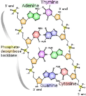
2.1.1 The structure of DNA
DNA is a molecule composed of two strands of nucleotides forming a double helix that is carrying genetic instructions for the development, functioning, growth and reproduction of organisms. The two DNA strands are known
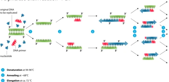
as polynucleotides as they are composed of simpler monomeric units called nucleotides. Each nucleotide is composed of one of four nitrogen-containing nucleobases (cytosine [C], guanine [G], adenine [A] or thymine [T]), a sugar called deoxyribose, and a phosphate group. The double helix has a fixed backbone which is composed by alternating phosphate and sugar groups. [14] The sugar in DNA is 2-deoxyribose, which is a pentose (five-carbon) sugar. The sugars are joined together by phosphodiester bonds between the third and fifth carbon atoms of adjacent sugar rings. These are known as the 3’-end (three prime end), and 5’-end (five prime end) carbons. There-fore, any DNA strand normally has one end at which there is a phosphate group attached to the 5’ carbon of a ribose (the 5’ phosphoryl) and another end at which there is a free hydroxyl group attached to the 3’ carbon of a ribose (the 3’ hydroxyl). The orientation of the 3’ and 5’ carbons along the sugar-phosphate backbone confers directionality to each DNA strand. The two opposite DNA strands are linked through hydrogen bonds between the nitrogen-containing nucleobases according to the complementary base pair-ing rule which states that DNA base pairs are always adenine with thymine (A-T) and cytosine with guanine (C-G). As a result the two strands are com-plementary and this yields the fact that the content of one strand defines the content of the opposite one. This complementary base pairing plays a great role in the creation of exact copies of a DNA molecule as one strand can be used to synthesize the corresponding complementary one. This process of creating copies is performed using special enzymes called Polymerases and the process of cloning is called Polymerace Chain Reaction (PCR)(see figure
2.3). In the DNA double helix, the direction of the nucleotides in one strand is opposite to their direction in the other strand: the strands are antiparal-lel. The asymmetric ends of DNA strands are said to have a directionality of five prime end (5’), and three prime end (3’), with the 5’ end having a termi-nal phosphate group and the 3’ end a termitermi-nal hydroxyl group. The bases lie horizontally between the two DNA strands (figure2.2). It is important to remark that during the process of PCR amplification the creation of the clone-strands follows a direction from the 5’end to the 3’end of the original DNA strands.
During PCR the original strands of DNA are separated and a polymerase enzyme is bound on special short DNA sequences (primers) which are spe-cific for the given enzyme. The enzyme glides upon each strand with di-rection from 5’end to 3’end constructing the corresponding complementary strand of each of the two original strands creating this way identical copies. PCR amplification can be repeated many times and after y PCR cycles there are 2ynew strands created.
In DNA coding this process of PCR is highly important for the introduc-tion of some extra redundancy in the produced DNA strands, which can be useful for error correction. More precisely, in the presence of multiple copies of an oligo, some of which might carry errors of insertions, deletions or sub-stitutions of nucleotides, one can easily compute the most representative con-sensus DNA sequence which is expected to be the closest to the correct one.
1https://commons.wikimedia.org/wiki/File:DNA_chemical_structure.svg 2https://creativecommons.org/licenses/by-sa/3.0/
3https://commons.wikimedia.org/wiki/File:Polymerase_chain_reaction.svg 4https://creativecommons.org/licenses/by-sa/3.0/deed.en
2.1. General workflow 13
Figure 2.2: The structure of a DNA molecule. (source:wikipedia1. Figure under creative commons license.2
2.1.2 DNA synthesis
Oligonucleotide synthesis is the chemical synthesis of DNA sequences. The majority of biological research and bioengineering involves synthetic DNA. Today, all synthetic DNA is custom-built using the phosphoramidite method by Marvin H. Caruthers. Oligos are synthesized from building blocks which replicate natural bases. The process has been automated since the late 1970s and can be used to form desired genetic sequences as well as for other uses in medicine and molecular biology. However, the chemical construction of DNA sequences is impractical beyond 200-300 bases and constitutes a haz-ardous process. These oligos, of around 200 bases, can be connected using DNA assembly methods, creating larger DNA molecules [15]. Although in-formation can be retrieved very quickly from DNA through next generation sequencing technologies, de novo synthesis of DNA is a major bottleneck in the process. Only one nucleotide can be added per cycle, with each cycle taking seconds, so the overall synthesis is very time consuming.
As described in [16] the commonly used phosphoramidite synthesis chem-istry consists of a four-step chain elongation cycle that adds one base per cy-cle onto a growing oligonucy-cleotide chain attached to a solid support matrix (Fig.2.4).
• In the first step, a dimethoxytrityl (DMT)-protected nucleoside phos-phoramidite that is attached to a solid support (usually contained within a synthesis column) is deprotected by the addition of trichloroacetic acid. This activates the support-attached phosphoramidite for chain elongation with the next phosphoramidite monomer.
• In the second step, the next base in the sequence is added in the form of a DMT-protected phosphoramidite and is coupled to the 50-hydroxyl group of the previous nucleoside phosphoramidite in the sequence form-ing a phosphite triester.
Figure 2.3: The process of Polymerace Chain Reaction (PCR) ex-plained (source: Wikipedia3, figure under creative commons licence
4
• Third, any unreacted 50-hydroxyl groups are capped by acylation to render any unextended sequences inert in subsequent rounds of the chain elongation cycle and thus reducing deletion errors in the finished oligonucleotide sequences.
• In the fourth step, the phosphite triester linkage between the monomers is converted to a phosphate linkage via oxidation with an iodine solu-tion to produce a cyanoethyl-protected phosphate backbone.
• The synthesis cycle then repeats for the next base in the sequence via the removal of the 50-terminal DMT protecting group. After the desired sequence has been synthesized from the 30 to 50, the oligonucleotide is chemically cleaved from the solid synthesis support and the protecting groups on the bases and the backbone are removed.
The above process has been automated since the late 1970s and can be used to form desired genetic sequences as well as for other uses in medicine and molecular biology. However, creating sequences chemically is imprac-tical beyond 200-300 bases, and is an environmentally hazardous process. These oligos, of around 200 bases, can be connected using DNA assembly methods, creating larger DNA molecules.
2.1.3 DNA sequencing
As described in section1.2, one can read the content of DNA strands with the use of some special machines, the sequencers. In practice, there are many different machines to perform sequencing. However, the most popular-ones for DNA data storage, are the Illumina sequencers which belong to the cate-gory of Next Generation Sequencing (NGS) and the Oxford Nanopore which is a more recent model and belongs to the group of third-generation DNA sequencers. To get a better idea of how sequencing works we will describe in this section the way those two models function for reading a DNA strand.
2.1. General workflow 15
Figure 2.4:The steps of a cycle of DNA synthesis (source: [16])
Illumina: One of the most accurate sequencing machines is the one of Illu-mina which reads DNA strands using a method called Sequencing by Syn-thesis (SBS). This method works in different cycles.
Figure 2.5:Illumina flowcell (source: [17])
Figure 2.6:Sequencing with illumina explained (source: [17]).
To begin with, short sequencing DNA-templates (which we will call primers), are immobilized on the surface of a proprietary flow cell surface (figure2.5) designed to present the DNA in a manner that facilitates access to enzymes. The primers that are bound on the flow-cell are complementary to the 3’ and 5’ ends (which we will call primers) of the oligos to be read allowing them to bind on the flow-cell’s sequencing templates as shown in (figure2.6b). In the next step, the free ends of the oligos bend and bind on the correspond-ing complementary templates formcorrespond-ing a bridge-like form (figure 2.6 c). In this phase of the sequencing the reading begins. Special enzymes allow the
2.1. General workflow 17
synthesis of the complementary strands by binding the corresponding nu-cleotides on the "bridge single strands". The complementary nunu-cleotides are fluorescently labeled using 4 different dyes according to the nucleotide type. Each time a nucleotide is bound in position, the fluorescent dye is imaged to identify the base and then enzymatically cleaved to allow incorporation of the next nucleotide. This is the reason why this process is called sequencing by synthesis. Once the double strands are created, they are separated again discarding the original strands and the same process will be repeated many times creating this way thousands of copies, which are frequently mentioned as reads, of each stored oligo. This process of copying the oligos by forming bridges and synthesizing the complementary strand is called Bridge Ampli-fication (BA). BA works similarly to PCR and is adding the required redun-dancy to allow denoising. More precisely, amplification creates up to 1,000 identical copies of each single stored oligo in close proximity creating a blob of the same oligo which is expected to emit at every new synthesis cycle the same sequence of fluorescent colors forming blobs of the same color which are easily identified (see figure2.7).
Figure 2.7: Illumina basecalling explained. Image from Illumina [17] showing how the four-colours work and the camera system in the older sequencers, the image of the cameras comes from the Bentley
Nature paper of 2008 [18]
Base calls are made directly from the signal intensity measurements dur-ing each cycle and thus raw error rates greatly reduces compared to other technologies. However, in the case that different oligos which are bound to neighboring regions on the Illumina flow-cell happen to have similar struc-ture of nucleotides the spotted color clusters might be overlapping merging the different color blobs into one, creating this way a difficulty in identify-ing the separate oligo structures and this way, introducidentify-ing some errors in the sequenced DNA strands. An image of the Illumina sequencer is depicted in figure2.8.
Figure 2.8:The Illumina sequencer1
Figure 2.9:Sequencing with Nanopore explained [19].
Oxford Nanopore: As revealed by the name a Nanopore sequencer consists of a flowcell of nano-scale pores (holes) through which passes a single strand of DNA. An ionic current is constantly passing through the nanopores at the same time with the DNA strands. As different nucleotides differ in size, each one of them will create a different change in the flow of ions when passing through the pore. The information about the change in current can be used to
2.2. A constrained problem 19
identify each molecule. More specifically, the changes in the ionic current as biological molecules pass through the nanopore or near it generate a signal which is then used for the decoding of each oligo.
The produced raw data (electrical signals) is processed using machine-learning techniques into basecalled data (the sequence of DNA bases). In other words, the electrical signals are translated into sequences of nucleotides. This procedure is carried out using kmer tables that translate sequentially fragments of the electrical signals into sets of nucleotides. A descriptive im-age of the function of the Nanopore sequencer is shown in figure2.9.
It is the smallest sequencing device currently available. It can plug di-rectly into a standard USB3 port on a computer with low hardware require-ment and simple configuration. It also allows to sequence longer reads (up to few hundred thousand base pairs), improving the assembly quality [20]. Its portability, affordability, and speed in data production makes it suitable for real-time applications, enabling the sequencing of full human genomes quickly and at affordable prices. However, some analysis on the results of MinION nanopore sequencer like [21] show that although the sequencing coverage is generally consistent, between 2% and 3% of the positions are underrepresented. Among those, approximately 50% were located at the be-ginning and the end of the reference sequence which can lead to the loss of both ends when its coverage does not reach20xsince we are not able to cor-rect and assemble those fragments. An image of the Illumina sequencer is depicted in figure2.10.
Figure 2.10: The MinION nanopore sequencer by Oxbord Nanopore Technologies2
2.2
A constrained problem
DNA synthesis is a procedure with a very low error-probability as long as the DNA strands to be synthesised do not overpass the length of 150-300 nts. For longer sequences the synthesis error increases exponentially. Conse-quently to reduce this error to minimum, the DNA sequences to be synthe-sized need to be cut into short pieces and formatted in such a way that the initial sequence can be correctly reconstructed in the decoding part. Detailed explanation for the formatting of the DNA sequence will be given in chapter
6.
On the contrary, the biological procedure of DNA sequencing introduces much error which can not be neglected and therefore there is a need for dealing with the erroneous oligos produced by the sequencer. Studies have
shown that the three main factors causing errors in the sequenced oligos are the following:
• Homopolymers: Consecutive occurrences of the same nucleotide should be avoided [22].
• G, C content: The percentage of G and C in the oligos should be lower or equal to the one of A and T [22].
• Pattern repetitions: The codewords used to encode the oligos should not be repeated forming the same pattern throughout the oligo length [23].
Taking into account all the above rules the sequencing error can be duced. Consequently, to be efficient, any DNA coding algorithm should re-spect the above rules in order to reduce as much as possible the probabilities of sequencing error. To this end, in chapter3of this work we propose a novel efficient encoding algorithm which can be used for the encoding of digital information into DNA using codewords that respect all those biological con-straints. Formatting Synthesis ENCODER {A,T, C,G} Mapping 4-ary code 4-ary code
Figure 2.11:Encoding of digital data into DNA.
2.2.1 Encoding
Until this point, it is clear that the encoding of digital data into DNA is strongly constrained by the biological part of the process. More precisely, to sum up the main obstacles which have been discussed in the previous sec-tions the encoding should provide a quaternary code which will respect the sequencing restrictions to ensure robustness and the length of the DNA oli-gos to be synthesised should not be higher than 150-300 nts. Consequently, the structure of a reliable encoder for DNA coding contains the following sub-parts (see figure2.11).
The first step in the encoding workflow is the construction of a dictionary of codewords composed by the symbols A, T, C and G similarly to the nu-cleotides of the DNA molecule. Those codewords should provide a robust encoding when assembled at a long sequence. This means that the quater-nary strands should not contain homopolymers, high G,C content compared to the content of A and T and finally it should not contain repeated patterns. The next sub-process of a DNA workflow is a mapping function which assigns input symbols to codewords of the quaternary code. This function can be a simple one to one function or a more sophisticated one. In later
2.3. Existing works 21
sections of this work we will extensively explain the mapping methods that have been used for our studies.
Finally, as the oligo length is restricted due to the synthesis limitations to avoid errors, it is necessary to adopt some formatting function for cutting the produced long encoding into shorter oligos and adding special headers for the reconstruction of the input at decoding. Those headers can contain information for the address of the data chunk in the original long sequence, information for any necessary encoding parameters as well as information about the input characteristics as for example the size. A general overview of the encoding of data into DNA is described by figure2.11.
2.2.2 Decoding
Since DNA data storage is a process which is prone to both writing and read-ing errors, the decodread-ing should include some techniques to predict, detect or even to correct the sequenced data. As explained in section 2.1.2, the addi-tion of redundancy is necessary for the detecaddi-tion of errors and can be easily achieved using the method of PCR amplification which is applied during both DNA synthesis and sequencing. Consequently, in the output of the se-quencer there will be multiple copies of each synthesised oligo. Each copy might contain different types of errors in various positions and this yields the need for selecting the most representative copy for each oligo. This selection can be based on computing a consensus sequence using all of the erroneous copies of each oligo or on finding the most frequent among all copies. This process can be followed by some error correction algorithm to treat any re-maining errors for obtaining an error free decoding. It is important to men-tion that the efficiency of the error correcmen-tion highly depends on the methods and machines that have been used during sequencing as some particular se-quencers can cause higher error rates than others and can therefore create stronger distortion. Finally using the inverse mapping function one can re-trieve the digital information which had been stored into DNA. An overview of the decoding process is described by figure2.12.
DECODER
Sequencing MappingInverse
Sequencing Error Oligo selection Deformatting Error correction {A,T, C,G} 4-ary code
Figure 2.12:Decoding of digital data stored into DNA.
2.3
Existing works
DNA data storage is a relatively new field of research and thus the state of the art is limited to a few pioneering works which have, however, contributed widely to this emerging topic.
2.3.1 First references to the idea of DNA data storage
The idea for storing digital data using the DNA molecule ages back in the late 50’s when soviet physicist Mikhail Samoilovich Neiman and cybernetician Norbert Wiener expressed ideas regarding the possibility of recording, stor-age, and retrieval of information on synthesized DNA and RNA molecules [24], [25]. However the first attempt of DNA data storage came in 1988 when the artist Joe Davis and researchers from Harvard collaborated for storing a 5 x 7 matrix in a DNA sequence in E.coli, which once decoded, formed a pic-ture of an ancient Germanic rune representing life and the female Earth [26]. In the matrix, ones corresponded to dark pixels while zeros corresponded to light pixels. In 2007 at the University of Arizona scientists create a device which is using addressing molecules to encode mismatch sites within a DNA strand. These mismatches were then able to be read out by performing a re-striction digest, thereby recovering the data. This was the starting point for various interesting works that followed, introducing multiple novel encod-ing algorithms that brought DNA data storage to practice and contributed widely to this emerging topic. In the following sections we will present the most widely used studies in the bibliography and briefly analyse the pro-posed solutions.
2.3.2 The first application of DNA data storage by Church et al.
In 2012, George Church et al. encode for the first time a 659-Kbyte book that was co-authored by Church into DNA. In their experiment the authors used a very simple encoding, by randomly translating zeros to A or C and ones to T or G [22]. The encoded sequence was then written onto a microchip as a series of DNA fragments using an ink-jet printer. The encoding resulted in 54,898 oligonucleotides, containing 96 bases of data along with a special 22-base sequence at each end to allow the fragments to be copied in parallel using the PCR amplification, and a unique, 19-base “address” sequence to denote the segment’s position in the original document.
The resulting PCR amplified oligos were then read back using an Illumina sequencer to retrieve the original text. The storage density of the DNA frag-ments produced by this method was estimated to be more than 700 terabytes per cubic millimeter. This result represented the largest volume of data ever artificially encoded in DNA, and proved that data density for DNA is sev-eral orders of magnitude greater than that of state-of-the-art storage media as shown in their plot in2.13.
Not only did this work make a pioneering step to prove the feasibility of using DNA as an alternative means of storage while demonstrating the extraordinary capacity compared to conventional storage devices but it also revealed that sequencing can be an error prone process. By analysing the different errors which occurred during sequencing this work provided a first study of the main constraints to be respected during the encoding.
After this important first step, several works followed to propose new encoding techniques, attempting to provide a robust encoding which would allow reducing the sequencing errors obtained in this study.
![Figure 1.3: The different types of storage according to data’s temper- temper-ature (image taken from [5].)](https://thumb-eu.123doks.com/thumbv2/123doknet/14745360.755989/31.892.234.700.124.336/figure-different-types-storage-according-temper-temper-ature.webp)
![Figure 2.4: The steps of a cycle of DNA synthesis (source: [16])](https://thumb-eu.123doks.com/thumbv2/123doknet/14745360.755989/42.892.133.728.127.618/figure-steps-cycle-dna-synthesis-source.webp)
![Figure 2.6: Sequencing with illumina explained (source: [17]).](https://thumb-eu.123doks.com/thumbv2/123doknet/14745360.755989/43.892.163.766.417.889/figure-sequencing-with-illumina-explained-source.webp)
![Figure 2.13: Results of the study carried out by Church et. al. [22]](https://thumb-eu.123doks.com/thumbv2/123doknet/14745360.755989/50.892.284.573.123.473/figure-results-study-carried-church-et-al.webp)
![Figure 2.14: Goldman et. al. encoding [1]](https://thumb-eu.123doks.com/thumbv2/123doknet/14745360.755989/51.892.223.699.126.460/figure-goldman-et-al-encoding.webp)