HAL Id: tel-02442208
https://tel.archives-ouvertes.fr/tel-02442208
Submitted on 16 Jan 2020HAL is a multi-disciplinary open access
archive for the deposit and dissemination of
sci-L’archive ouverte pluridisciplinaire HAL, est destinée au dépôt et à la diffusion de documents
Development of a thermal-hydraulics/thermomechanics
coupling model for the evaluation of the behavior of
SFR fuel assemblies under irradiation
Francisco Acosta
To cite this version:
Francisco Acosta. Development of a thermal-hydraulics/thermomechanics coupling model for the evaluation of the behavior of SFR fuel assemblies under irradiation. Nuclear Experiment [nucl-ex]. Université Grenoble Alpes, 2019. English. �NNT : 2019GREAI059�. �tel-02442208�
THÈSE
Pour obtenir le grade de
DOCTEUR DE LA COMMUNAUTE UNIVERSITE
GRENOBLE ALPES
Spécialité : MEP : Mécanique des fluides Energétique,
Procédés
Arrêté ministériel : 25 mai 2016
Présentée par
Francisco ACOSTA
Thèse dirigée par Pablo RUBIOLO, Professeur, Communauté Université Grenoble Alpes
et codirigée par Thierry CADIOU et Victor BLANC, CEA
préparée au sein du Laboratoire d’Etudes et de Modélisations
des Systèmes (CEA/DEN/CAD/DER/SESI/LEMS) et dans l'École Doctorale I-MEP2 - Ingénierie - Matériaux, Mécanique,
Environnement, Energétique, Procédés, Production
Développent d'une méthodologie de
couplage thermo-hydraulique et
thermomécanique pour l'évaluation du
comportement sous irradiation des
assemblages combustibles des RNR-Na
Development of a thermal-hydraulics /
thermomechanics coupling methodology
for the evaluation of the behavior of SFR
fuel subassemblies under irradiation
Thèse soutenue publiquement le 15 octobre 2019, devant le jury composé de :
Monsieur PABLO RUBIOLO
PROFESSEUR, GRENOBLE INP, Directeur de thèse
Monsieur EMILIO BAGLIETTO
PROFESSEUR ASSOCIE, INSTITUT DE TECH. DU MASSACHUSETTS - USA, Rapporteur
Monsieur FREDERIC LEBON
PROFESSEUR, UNIVERSITE AIX-MARSEILLE, Président
Madame EMILIE FERRIE
Résumé
Les faisceaux d’aiguilles des assemblages combustibles des réacteurs à neutrons rapides à caloporteur sodium (RNR-Na) se déforment au cours de leur irradiation, ce qui impacte l’écoulement du caloporteur et la distribution de températures dans l’assemblage, dont la connaissance est essentielle pour la démonstration de sûreté. De plus, les mécanismes à l’origine de cette déformation, à savoir le gonflement et le fluage thermique et d’irradiation, dépendent fortement de la température de la gaine du combustible, d’où l’existence d’un couplage entre les évolutions thermo-hydraulique et thermomécanique des assemblages. Par le passé, ce couplage a été négligé dans les simulations numériques, et une approche plus conserva-tive a été privilégiée : les simulations thermo-hydrauliques étaient réalisées sans tenir compte de la déformation géométrique, et les distributions de températures résultantes étaient utilisées comme des données d’entrée pour les simulations ther-momécaniques. L’objectif de cette thèse est de définir une méthodologie pour l’évaluation du comportement des assemblages combustibles de type RNR-Na sous irradiation en prenant en compte le couplage entre leurs évolutions thermo-hydraulique et thermomécanique.
A cet effet, un nouveau couplage numérique a été développé entre le code indus-triel de dynamique des fluides numérique (CFD) STAR-CCM+ et DOMAJEUR2, code basé sur la méthode aux éléments finis et dédié à la modélisation du comporte-ment thermomécanique des assemblages combustibles RNR-Na sous irradiation. Ce couplage a été réalisé par l’échange de la déformation de la gaine, calculée par DOMAJEUR2, et de son champ de températures, obtenu avec le modèle CFD qui prend en compte de manière explicite la déformation géométrique des aiguilles combustibles. De plus, les conditions aux limites thermo-hydrauliques utilisées dans les simulations CFD, comme le débit massique de sodium dans le faisceau, sont ajustées pour tenir compte de cette déformation.
Cette méthodologie a été appliquée à des faisceaux respectivement de 7 et 19 aigu-illes combustibles munies de fils espaceurs, avec des caractéristiques géométriques et des conditions aux limites représentatives des RNR-Na de quatrième génération, ont été analysés. Dans le cas des faisceaux combustibles fortement irradiés, les simulations couplées conduisent à une réduction significative de la déformation diamétrale des aiguilles combustibles, par rapport aux simulations non couplées, causée par la prise en compte de l’augmentation de la température de la gaine
maximale de la gaine a été réduite. De plus, des simulations ont été menées afin de vérifier que, en situation de fonctionnement normal, la dépendance de la neutron-ique à l’évolution de la thermo-hydraulneutron-ique et de la thermomécanneutron-ique est faible. Enfin, une contribution à la validation de cette méthodologie de simulation couplée a été réalisée avec un benchmark numérique basé sur un outil de simulation couplé existant et en simulant l’irradiation d’un assemblage combustible expérimental. Contrairement à l’approche innovante développée dans le cadre de ce travail de thèse, l’outil de simulation existant utilise un modèle thermo-hydraulique simplifié et ne tient pas compte de l’impact de la déformation sur le débit massique du caloporteur, qui, selon les résultats de l’évaluation, a une importance majeure. La simulation de l’irradiation expérimentale a conduit à une déformation maximale de la gaine et un gradient de déformations en accord avec les grandeurs mesurées, bien que des limitations liées aux lois empiriques de gonflement utilisées dans DOMAJEUR2 pour le calcul du gonflement aient été identifiées. La reformulation de ces lois à l’aide de la méthodologie de simulation couplée développée constitue une perspective à ce travail de thèse.
Abstract
The fuel pin bundles of Sodium-cooled Fast Reactors (SFR) undergo significant geometrical changes during their irradiation, which affect the coolant flow and temperature distributions in the fuel subassemblies, the knowledge of which is essential for safety assessments. Moreover, as the mechanisms responsible for the deformation of the fuel bundles, namely the swelling and creep, strongly depend on the fuel cladding temperature, a coupling between the thermal-hydraulic and thermomechanical evolutions of the fuel subassemblies exists. In the past, this coupling has been neglected in the numerical simulations, and a more conservative approach has been preferred. In this conservative approach, the thermal-hydraulic simulations are conducted without considering the geometrical deformation, and the resulting temperature distributions are used as input for the thermomechanical simulations. The objective of this thesis is to define a new methodology for the evaluation of the behavior of SFR fuel bundles under irradiation that considers the coupling between their thermal-hydraulic and thermomechanical evolutions.
To this end, a new numerical coupling has been developed between the industrial Computational Fluid Dynamics (CFD) code STAR-CCM+ and DOMAJEUR2, a finite element code dedicated to the modeling of the thermomechanical behavior of SFR fuel subassemblies under irradiation. The coupling has been implemented via the exchange of the cladding deformation, calculated by DOMAJEUR2, and its associated temperature field, obtained with a CFD model implemented in STAR-CCM+ that explicitly considers the geometrical deformation of the fuel pins. In addition, the thermal-hydraulic boundary conditions used in the CFD simulations, such as the sodium mass flow rate through the bundle, are also adjusted to account for the deformation.
Fuel bundles of 7 and 19 wire-wrapped pins, with geometrical characteristics and boundary conditions representative of fourth generation SFRs, were analyzed in order to gain insight on the effects of the coupling. For highly irradiated fuel bundles, the coupled simulations were shown to lead to a significant reduction of the diametral strain of the fuel pins, with respect to non-coupled simulations, caused by the deformation-induced cladding temperature increase. Consequence of the lower deformation, the cladding maximal stress was also significantly re-duced. Additionally, neutronic simulations were conducted in order to verify that,
thermomechanics is of minor importance. Finally, a contribution to the validation of the developed coupled simulation methodology was realized by performing a numerical benchmark against a preexisting coupled simulation tool, and by sim-ulating the irradiation of an experimental fuel subassembly. Unlike the novel approach developed in this work, the preexisting simulation tool employs a simpli-fied thermal-hydraulic model and does not consider the impact of the deformation on the coolant mass flow rate, which was found to be of major importance. The simulation of the experimental irradiation yielded a maximal cladding deformation and deformation gradient that are in good agreement with the measured values, although limitations related to the empirical laws employed in DOMAJEUR2 to compute the swelling were identified. The reformulation of these laws using the developed coupled simulation methodology is part of the future outlook of this work.
Acknowledgements
I would firstly like to thank the CEA for giving me the opportunity to conduct this PhD and, in particular, to Manuel Saez, head of the LEMS laboratory, for his continuous support during these three years. I am also very grateful for the dedication of Thierry Cadiou and Victor Blanc, my tutors, and Pablo Rubiolo, my thesis director. This work would not have been possible without your advice, guidance, and patience.
I would also like to thank my colleagues; I really enjoyed working with you. Special thanks to Edouard, with whom I shared the office and the PhD headaches, and to Nicolas Alpy, Vincent Pascal and Nicolas Schmidt for the many technical discussions we had.
My sincere thanks also goes to all the members of the jury for the time they spent reading this manuscript and for their valuable comments and questions.
Last but not least, I would like to thank my friends, my family, and Uta. Thank you for encouraging me to take this path, and thank you for helping me walk it. I could not have done it without your support.
Contents
Contents vii
List of Figures x
List of Tables xxi
List of acronyms xxii
1 Introduction 1
1.1 The fourth generation of nuclear reactors . . . 1
1.2 Sodium-cooled Fast Reactors . . . 2
1.2.1 SFR system . . . 2
1.2.2 Fast neutron energy spectrum . . . 3
1.2.3 Liquid sodium as coolant . . . 5
1.2.4 SFR fuel subassemblies . . . 6
1.2.5 SFR bundle deformation . . . 8
1.3 Numerical simulations and multiphysics. . . 10
1.3.1 Need for comprehensive simulations . . . 10
1.3.2 Traditional and multiphysical simulations of the evolution of SFR subassemblies . . . 12
1.4 Motivations and goals of this work . . . 15
1.5 Structure of the manuscript . . . 16
2 SFR subassembly evolution. Phenomenology of a multiphysical system 17 2.1 Thermal-hydraulics . . . 19
2.1.1 Generalities . . . 19
2.1.2 Turbulent flow regime . . . 20
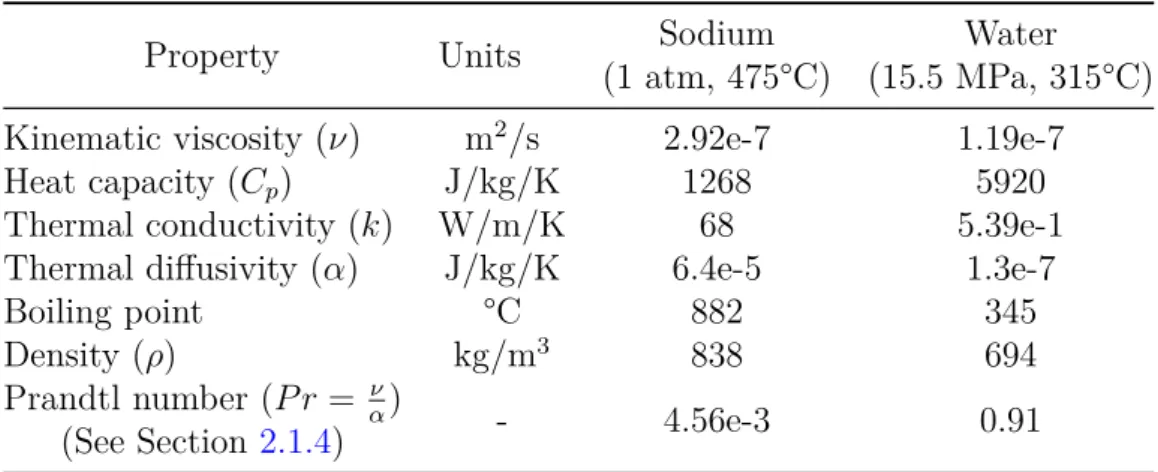
2.1.3 Sodium properties . . . 22
2.1.4 Low Prandtl flows. . . 23
2.1.5 Characteristics of sodium flow in wire-wrapped fuel pin bundles 26 2.1.6 Pressure drop in SFR subassemblies. . . 28
2.1.7 Axial distribution of sodium temperature . . . 31
2.1.8 Section summary . . . 32
2.2 Thermomechanics . . . 32
2.2.1 Evolution of the external loads . . . 33
2.2.3 Materials employed for the cladding and the hexcan . . . 53
2.2.4 Pellet cladding interaction . . . 53
2.2.5 Deformation of SFR fuel bundles during irradiation . . . 54
2.2.6 Section summary . . . 59
2.3 Neutronics . . . 60
2.3.1 Generalities . . . 60
2.3.2 Reactivity feedbacks . . . 63
2.3.3 Irradiation dose calculation . . . 65
2.3.4 Section summary . . . 66
2.4 Phenomenological summary and simulation assumptions . . . 66
3 Numerical simulation of the thermal-hydraulics of SFR subassemblies 71 3.1 Available methods for simulating the thermal-hydraulics of SFR subassemblies . . . 72
3.1.1 Subchannel analysis. . . 72
3.1.2 Computational Fluid Dynamics . . . 74
3.2 Reynolds-Averaged Navier-Stokes . . . 78
3.2.1 RANS conservation equations . . . 78
3.2.2 Closure problem. . . 80
3.2.3 Turbulence models . . . 81
3.2.4 Near wall modeling . . . 82
3.3 Implemented CFD-RANS model . . . 84
3.3.1 STAR-CCM+ . . . 84
3.3.2 Selected fluid models . . . 85
3.3.3 Turbulence model and wall treatment . . . 86
3.3.4 Simulation domain and boundary conditions . . . 88
3.3.5 Meshing . . . 90
3.3.6 Wire-cladding contact representation . . . 91
3.4 Summary . . . 92
4 Numerical simulation of the thermomechanics of SFR subassemblies 94 4.1 Single fuel pin and entire fuel bundle simulation approaches . . . . 94
4.2 General presentation of DOMAJEUR2 . . . 95
4.3 Input data and boundary conditions . . . 97
4.4 3D and 1D finite element representation . . . 98
4.4.1 Detailed 3D model . . . 98
4.4.2 Project 1D model . . . 101
4.5 Summary . . . 105
5 Coupling Methodology 107 5.1 Preexisting coupled approaches . . . 108
5.2.2 Algorithm . . . 117
5.2.3 Implementation . . . 123
5.3 CFD of deformed fuel bundles . . . 126
5.3.1 Generation of the CAD model of a deformed bundle . . . 126
5.3.2 Model to estimate the coolant mass flow rate in deformed subassemblies . . . 135
5.3.3 Heat flux in the deformed bundle . . . 140
5.3.4 Post-processing of the CFD simulations . . . 141
5.4 Thermomechanics of the fuel bundle . . . 146
5.4.1 Defining the temperature history . . . 146
5.4.2 Post-processing of the thermomechanical simulations . . . . 150
5.5 Summary . . . 151
6 Reduced bundles study cases 153 6.1 Definition of the study case . . . 154
6.2 Conjugate heat transfer . . . 156
6.3 Neutronic feedbacks. . . 163
6.4 Convergence of the coupled simulations . . . 168
6.5 Impact of deformation on thermal-hydraulics . . . 170
6.6 Effects of the coupling on the bundle deformation . . . 176
6.7 Effects of the coupling on the cladding stresses . . . 189
6.8 Comparison between different temperature interpolation methods . 199 6.9 Summary . . . 208
7 Application cases 209 7.1 Simulation of an irradiation experience: Phenix subassembly . . . . 210
7.1.1 Case description. . . 211
7.1.2 Simulation results . . . 214
7.2 Numerical benchmark: Joyo subassembly . . . 220
7.2.1 Benchmark definition . . . 221
7.2.2 Results comparison . . . 224
7.3 Summary . . . 238
8 Conclusions and outlooks 239 Bibliography 244 Appendices 264 A CFD mesh and mesh dependency . . . 264
List of Figures
1.1 Pool-type SFR system (H. Ohshima and Kubo 2016). . . 3
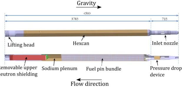
1.2 Fuel subassembly of an advanced SFR prototype (Beck, Blanc, Escleine, et al. 2017). The dimensions are in mm. . . 7
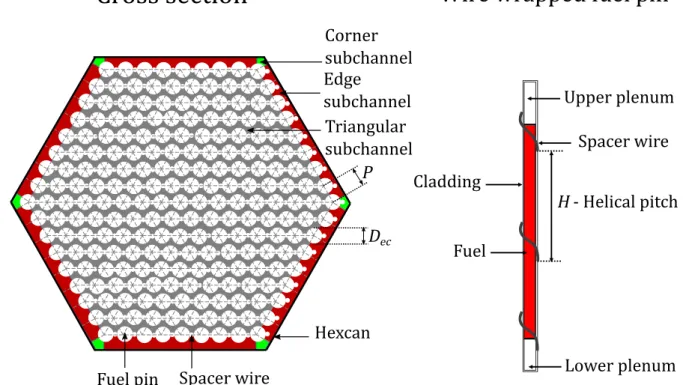
1.3 Cross section of a SFR fuel subassembly and schematic representation of one fuel pin (adapted from Saxena 2014). . . 8
1.4 a) Measured axial profile of diametral strain of a fuel pin irradiated in Phenix reactor. The heated column of the fuel pin—where most of the fission energy is produced—is indicated. b) Image of a highly ovalised fuel pin. c) Image of fuel pins that exhibit a very high helical flexion. . . 10
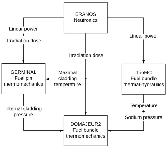
1.5 Traditional SFR subassembly simulation scheme. Example of the strategy employed at the CEA. . . 13
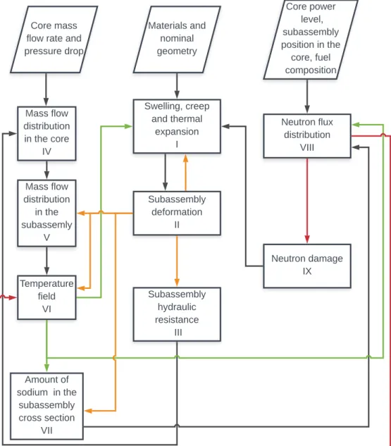
2.1 Main physical phenomena involved in the evolution of SFR sub-assemblies under irradiation in nominal operating conditions. . . 18
2.2 Laminar (a) and turbulent (b) time-averaged axial velocity (u) profiles for the flow in a circular pipe (Smits and Marusic 2013). . . 22
2.3 Effect of P r number on the thickness of the thermal and momentum boundary layers in the case of a flow with free stream temperature
T0 over a semi infinite plate at temperature Tw (OECD/NEA 2015). 24
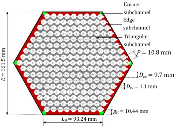
2.4 Cross section of the fuel bundle of the advanced SFR designed at the CEA. Adapted from (Saxena 2014). . . 27
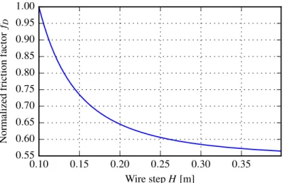
2.5 Normalized friction factor as a function of H, computed with Rehme’s correlation. . . 30
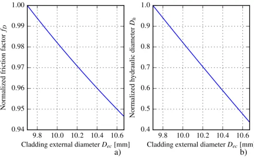
2.6 Normalized friction factor computed with Rehme’s correlation (a) and normalized hydraulic diameter (b) as a function of the cladding external diameter.. . . 31
2.7 Axial distribution of cladding temperature for a central pin of a Phenix subassembly, of the sodium temperature within a subchannel in contact with the cladding, and of the linear power and neutron flux, as computed by the code employed to follow the operation of the reactor (Pelletier 2018). . . 34
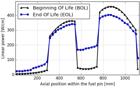
2.8 BOL and EOL linear power profile of an axially heterogeneous fuel pin.. . . 36
2.10 Yield stress change of stainless steel irradiated in three reactors with different neutron energy spectra, as a function of fluence and of irradiation dose in dpa (Gary S. Was 2007). . . 40
2.11 Axial profiles of normalized cladding irradiation dose for an axially homogeneous and an axially heterogeneous fuel concept. . . 41
2.12 Schematic representation of swelling rate (a) and of the cumulated swelling as a function of the irradiation dose, as determined by an empirical law. . . 46
2.13 Steady state swelling rate as a function of temperature (a), and temperature dependence of the swelling incubation dose and, for two different irradiation doses, of the cumulated swelling (b). These re-sults correspond to the reference austenitic steel for the fuel claddings of the advanced SFR designed at the CEA. . . 47
2.14 Strain rates induced by the steady state swelling and by irradiation creep for different stress levels, as a function of temperature. These rates represent the asymptotic behaviour predicted by the empirical laws, since the steady state swelling rate was considered to compute the irradiation creep strain rate. These results correspond to the reference austenitic steel for the fuel claddings of the advanced SFR designed at the CEA. . . 51
2.15 Irradiation-induced changes in the tensile properties of cold-worked, Ti-stabilized steel samples irradiated in Phenix reactor, as a function of temperature (F. Garner 2006). . . 52
2.16 Schematic representation of the start of the 2nd (a) and 3rd (b)
phases of interaction between the fuel pins, and between the pins and the hexcan. Adapted from (Uwaba and K. Tanaka 2001). c) Scheme of a compact plane. . . 55
2.17 a) Maximal diametral strain of fuel pins fabricated with different steels (see Section 2.2.3) irradiated in Phenix reactor, as a function of the irradiation dose (Yvon, Le Flem, Cabet, et al. 2015). The embrittlement limit discussed in Section 2.2.2.2 is shown, assuming a dominant contribution of swelling to the total diametral strain. b) Axial profile of diametral strain of a Phenix fuel pin showing that the strain is concentrated in the heated column. . . 57
2.18 Schematic representation of the progression of the helical flexion of the fuel pins during their irradiation, and image of irradiated fuel pins presenting an extremely high helical flexion (Cadiou and Acosta 2018). . . 58
2.19 Schematic representation of the progression of the cladding ovalisa-tion under the contact forces and countered by the internal fission gas pressure (FG), and image of a highly ovalised fuel cladding (Cadiou and Acosta 2018). . . 58
2.20 Reactivity effect of sodium voiding in the different regions of the core of the advanced SFR designed at the CEA, expressed in pcm (Coquelet-Pascal, Venard, Sciora, et al. 2017). . . 65
3.1 Example of a control volume in subchannel analysis. Tk
i represents
the temperature in the node k of the subchannel i.. . . 72
3.2 Example of the sodium temperature distribution computed with subchannel analysis (Wu, Li, X. Yu, et al. 2013). . . 73
3.3 Energy flux from large to small scales (Andersson 2012). . . 77
3.4 Non-dimensional velocity profile in the inner boundary layer (Saxena 2014). . . 84
3.5 Representation of the CFD simulation domain. The hydraulic bound-ary conditions at the entrance and outlet of the domain are indicated, as well as the fuel pin naming system.. . . 88
3.6 Example of the mesh obtained for a 7-pin bundle. . . 91
3.7 Wire cladding interpenetration (a) and circular filleting of the contact edges (b) . . . 92
4.1 7-pin fuel bundle and hexcan representation with 3D volumetric finite elements. The spacer wires, one of which is highlighted in red, are represented with 1D beam elements. . . 99
4.2 Potential mechanical contacts between adjacent fuel pins (a) and between a fuel pin and the hexagonal can (b). . . 100
4.3 217-pin fuel bundle and hexcan representation with beam and shell elements, respectively. A detail of the 12 beam elements present in one wire step is shown. . . 101
4.4 a) 3D simulation of the crushing of a fuel cladding under contact forces of magnitude F and an internal pressure P . b) Scheme of the modified bar element, linking the neutral axis of the pipe elements that represent the claddings, employed to simulate the crushing of the cladding. . . 106
5.1 a) Scheme of the algorithm of a non-iterative explicit OS coupling. TM represents one time step of the thermomechanical simulation, which computes the deformation distribution D at the end of the step. Each thermal-hydraulic simulation, which yields the temper-ature distribution T , is denoted by TH. The dependence of the position r of these distributions is here dropped for simplicity. b) Scheme of the algorithm of an OS coupling in which the deformation computed at the end of a given time step and the temperature dis-tribution obtained in a geometry characterized by that deformation are converged by performing iterations. . . 111
5.2 Scheme of the algorithm of the OS coupling developed in this work, in which the thermomechanical simulation of the entire irradia-tion period is conducted in each global iterairradia-tion, using as input a prescribed temperature history ˜Tk(t) which is updated in each
iteration. . . 114
5.3 Schematic representation of the initialization stage of the coupled simulation, which corresponds to the traditional practice for sim-ulating SFR fuel subassemblies. The temperature time evolution corresponds to a given point within the fuel bundle, and the diame-tral deformation of the cladding at that point is used to represent the evolution of the geometry of the bundle. A reactor heating up phase between t = 0 and t = tBOL is represented. . . 115
5.4 Schematic representation of the iterative stage of the coupled simu-lation. The trends observed for the temperature and deformation distributions in the coupled calculations are represented in red, and correspond to a given point within the fuel bundle. In this example, a linear temperature evolution between BOL and EOL is considered after the initial heating up phase. . . 115
5.5 Scheme of the algorithm of the OS coupling developed in this work, for the particular case of K = T. In this case, every temperature distribution T (ti) is obtained with a CFD simulation in the geometry
characterized by the deformation D(ti). The dependence on r of
these distributions is here dropped for simplicity. . . 118
5.6 Scheme of the algorithm of the OS coupling developed in this work, in the general case where the deformation computed at every time step of the last thermomechanical simulation is also used as input of the interpolation function f, used to compute the temperature history
˜
Tk(r, t) used as input for the next thermomechanical simulation. . 123
5.7 Scheme of the main steps of the coupled simulation algorithm. . . . 125
5.8 Rotation of the axial profile of cladding external radius that produces a solid body with rotational symmetry, which represents the fuel pin. 127
5.9 Sketch of the tilted cross section of a spacer wire, normal to the helical path that defines the position of its center along its length. . 128
5.10 CAD representation of a fuel pin and its spacer wire. . . 129
5.11 Sketch of the upper end of the CAD representation of a wire-wrapped fuel pin. In (a), the upper face of the wire is normal to the axial direction z, and contained in the plane that defines the boundary of the fluid domain. In (b), the upper face of the wire is tilted, giving place to a thin fluid wedge.. . . 130
5.12 Example of a solid body created by a loft CAD operation, joining 3 elliptic sketches. The planes on which the sketches are defined are also indicated. . . 131
5.13 Sketch of a twisted fuel pin, of its tilted cross section at z = zi and
of the horizontal cross section, at z = zj, employed—given the small
value of the angle α—as an approximation to construct the CAD model of the pin. . . 132
5.14 CAD representation of a helically flexed fuel pin and its spacer wire. The lateral displacement of the pin computed by DOMAJEUR2 has been multiplied by 40 to obtain the CAD model presented in this figure. . . 133
5.15 Diagram of one subassembly. The heated column is the only part that is considered to undergo deformation, and it is highlighted in red. . . 137
5.16 Normalized mass flow rate and pressure drop in the heated column and in the rest of the subassembly, as a function of the average diametral strain of the heated column of the fuel bundle of the advanced SFR designed at the CEA. . . 139
5.17 Probe line used to sample the cladding surface temperature. Some of the points where it intersects the spacer wire or becomes close to a neighbouring wire are indicated. . . 143
5.18 Example of a cladding surface temperature axial profile. The tem-perature jumps induced by its spacer wire are encircled in red, and the local heating induced by a neighboring spacer wire are encircled in blue. . . 143
5.19 Distribution of the probe points used to sample the cladding surface temperature.. . . 144
5.20 Examples of cladding surface temperature axial profiles. Each tem-perature value is computed by averaging the temtem-peratures of the probe points present, at that axial position, in a circumference arc on the surface of the cladding of either 30°or 60°. . . 145
5.21 Schematic representation of a typical temperature time evolution
T(r0, t), at constant subassembly power, and of different
approxi-mating functions. A point r0 within the fuel bundle is considered. In the "Delayed T increment" approximation, the effects of deformation on temperature are considered only after a time tinc.. . . 147
5.22 Example of the fitting of εk−1
M ax(t) employed to determine tkinc. . . . 149
6.1 a) Axial profiles of linear power and irradiation dose employed in the numerical simulations of the 7-pin fuel bundle. b) Cross section of the CFD mesh at the outlet of the 7-pin bundle, where the pin naming system is indicated. . . 155
6.2 Temperature distribution at the outlet of the heated column, com-puted by the CHT simulation. . . 158
6.3 Axial profile of cladding temperature at its external surface, com-puted by the CHT and by the fluid only CFD simulations, for the central pin A1. The profiles correspond to azimuthal angles of 0° and 120°. . . 159
6.4 Axial profile of cladding temperature at its external surface, com-puted by the CHF and by the fluid only CFD simulations, for the peripheral pin B6. The profiles correspond to azimuthal angles of 0° and 120°. . . 159
6.5 Axial distribution of the difference in the cladding surface tempera-ture computed by the CHT and by the fluid only CFD simulations, for the peripheral pin B6, at azimuthal angles of 0°and 120° . . . . 160
6.6 Comparison of the cladding temperature at its internal surface (at a radius r = ric) and at its external surface (r = rec), as computed by
the CHT and the fluid only CFD simulations. The profiles presented correspond to the peripheral pin B6 at an azimuthal angle of 120°. The normalized profile of linear power is also presented. . . 161
6.7 Heat flux as a function of the azimuthal angle, for the central pin A1 (a) and the peripheral pin B1 (b), at the axial position z = 0.555 m.163
6.8 a) Angular sector of the cross section of the core, where the internal and internal subassemblies are indicated. b) Cell representation of one fuel subassembly. c) Zoom on one fuel pin in the cell represen-tation of a fuel subassembly, in which different components of the cell are indicated. . . 166
6.9 a) Angular sector of the core of Case I, where the modified subassem-blies are indicated in yellow. The core presents a 120°symmetry. b) Distribution of the subassembly power change computed in Case I with respect to the nominal, non-deformed core. . . 168
6.10 a) Axial profiles of the average diametral strain of the central pin, computed by the successive DOMAJEUR2 calculations in one cou-pled simulation. The N°0 simulation uses the nominal temperature distribution as input. b) Axial profiles of cladding surface tem-perature of the central pin, at an angle θ = 0°, computed with the successive CFD calculations in one coupled simulation. The N°0 simulation is conducted in the non-deformed geometry, and it provides the nominal temperature distribution.. . . 170
6.11 Cladding surface temperature along the heated length of the central pin, obtained by averaging for each altitude, over one sixth of the cladding circumference centered in the red cross indicated in the diagram (a) and axial profiles of sodium bulk temperature (b) for the deformed and non-deformed bundles. . . 172
6.12 Sodium temperature at the outlet of the heated column computed in the non-deformed geometry, and in the most deformed geometry— with an average diametral strain of 4.9%—with and without reducing the coolant mass flow rate. The temperatures sampled over a diago-nal at θ = 0◦ are presented in (a), the ones sampled over a diagonal
at at θ = −60◦ in (b), and these two diagonal sampling lines are
indicated in (c), where the outlet sodium temperature distribution in the nominal geometry is presented. . . 173
6.13 Temperature distribution around the peripheral pin B6, at the outlet of the heated column, in the deformed and non-deformed geometries.175
6.14 Sodium temperature at the outlet of the heated column of the non-deformed (a) and non-deformed (c) bundle. The sodium velocity vectors in one of the gaps closed by the deformation is also presented (b). . 176
6.15 Diametral strain of the cladding of the peripheral pin B6 (a) and of the central pin A1 (b) along the heated column, obtained with and without coupling, for a maximal irradiation dose of 123 dpa. . . 177
6.16 Diametral strain of the cladding of the peripheral pin B6 (a) and of the central pin A1 (b) along the heated column, obtained with and without coupling, for a maximal irradiation dose of 165 dpa. . . 178
6.17 Cladding swelling as a function of temperature, for two different irradiation dose levels, as calculated with the empirical law employed in DOMAJEUR2. . . 179
6.18 Average cladding temperature along the heated column of the central and one peripheral pin of the non-deformed bundle. The temperature ranges that maximize swelling and irradiation creep—for a dose range of [100,165] dpa—are indicated. . . 180
6.19 Detail, at the upmost section of the fuel bundle, of the temperature distribution used as input for the DOMAJEUR2 simulations when 1 averaged temperature profile per pin is employed (a) and when 6 different profiles per pin are used (b). . . 181
6.20 Diametral strain profile of the peripheral pin B6 obtained with DOMAJEUR2 using one and six axial temperature profiles per pin, for a maximum dose of 165 dpa (a) and 123 dpa (b). . . 182
6.21 Diametral strain profile of the central pin obtained with the 3D and 1D models of DOMAJEUR2, for a maximum dose of 165 dpa (a) and 123 dpa (b). . . 183
6.22 Axial profiles of swelling strain computed with the 1D and the 3D models of DOMAJEUR2, in coupled and non-coupled simulations. The results obtained for the central pin A1 (a) and the peripheral pin B2 (b) are presented. . . 185
6.23 Axial profiles of irradiation creep hoop strain computed with the 1D and the 3D models of DOMAJEUR2, in coupled and non-coupled simulations. The results obtained for the central pin A1 (a) and the peripheral pin B2 (b) are presented. . . 186
6.24 a) Swelling strain in the circumference of the cladding of a periph-eral fuel pin, at an altitude z = 0.545 m, computed with the 3D model of DOMAJEUR2 in a coupled and a non-coupled simulation. b) Swelling strain distribution within a 1.5 cm tall section of the cladding, centered at z = 0.545 m, computed with the 3D model of DOMAJEUR2 in a coupled and a non-coupled simulation. . . 187
6.25 Axial profile of the equivalent stress predicted by the 1D DOMA-JEUR2 model, for the central pin A1 (a), and for the peripheral pin B2 (b). . . 190
6.26 Scheme of the fuel pins within a diagonal of the hexcan. The segments employed to compute the available space, within the hexcan, to accommodate the diametral strain of the pins (TAH) are indicated in red and blue. . . 191
6.27 Evolution of the TAG and of the equivalent cladding stress (σeq) at
the axial position of maximal EOL stress, for the central pin A1. The results obtained with coupled and not coupled simulations are presented, and the TAG limits marking the start of the 2nd and 3rd
bundle deformation phases are shown.. . . 192
6.28 Evolution of the TAG and of the equivalent cladding stress (σeq) at
the axial position of maximal EOL stress, for the peripheral pin B2. The results obtained with coupled and not coupled simulations are presented, and the TAG limits marking the start of the 2nd and 3rd
bundle deformation phases are shown.. . . 193
6.29 Evolution of the equivalent cladding stress at the axial position of maximal EOL stress, for the central pin A1. The results obtained with the 1D and the 3D models in coupled and not coupled simula-tions are presented, and the axial position evaluated in each model is indicated. . . 196
6.30 Evolution of the equivalent cladding stress at the axial position of maximal EOL stress, for the central pin A1. The results ob-tained with the 1D and the 3D models in coupled and not coupled simulations are presented. . . 197
6.31 Cladding surface temperature axial distribution of the central pin A1 (a) and the peripheral pin B2 (b), in the non-deformed geometry. Each profile corresponds to a different azimuthal angle. . . 198
6.32 a) BOL and EOL linear power axial profiles used for all the fuel pins of the 19-pin bundle. b) Cross section of the CFD mesh at the outlet of the fuel bundle, where the pin naming system is indicated. 201
6.33 a) Cladding temperature evolution at z = 0.54 m obtained with the coupled simulations—with two different temperature interpolation methods—and without coupling, for three different fuel pins. b) EOL diametral strain profiles computed in each simulation and for each pin. . . 202
6.34 Maximal cladding surface temperatures of all fuel pins computed with the coupled simulations using different temperature interpolation methods, compared to the ones obtained without coupling. . . 203
6.35 a) Evolution of the average viscoplastic diametral strain of the fuel pins of the bundle, computed with coupled simulations with two different temperature interpolation methods, and without coupling. The maximal average strain computed amongst all simulations was used for the normalization. b) Evolution of the difference in the average viscoplastic diametral strain computed with the two coupled simulations, normalized with the maximal difference. . . 204
6.36 a) Cladding temperature evolution at z = 0.54 m obtained with the coupled simulations—with two different temperature interpolation methods—, compared to the evolution computed by including two intermediate CFD simulations, and to the results obtained without coupling, for three different fuel pins. b) EOL diametral strain profiles computed in each simulation and for each pin.. . . 207
7.1 Distribution of the normalized maximal EOL irradiation dose calcu-lated within the fuel bundle of MYOSOTIS, which presents a high radial gradient due to its peripheral position within the core. The positions of the most and least irradiated fuel pins (pin N°1 and N°217, respectively) are indicated. . . 212
7.2 a) Evolution of the normalized maximal linear power of MYOSOTIS. The encircled S1 and S2 states correspond to the first and last, respectively, in which Phenix reactor was operating at full power. Each reported value corresponds to the state at the end of an irradiation cycle. b) Normalized BOL and EOL axial profiles of linear power employed in the simulations for the corner pin N°1, which correspond to the states S1 and S2, respectively. . . 213
7.3 Axial profiles of average cladding surface temperature for the central pin N°109 (a) and the corner pin N°1 (b), computed with CFD simulations in nominal and deformed geometries with the same EOL sodium mass flow rate and power. The outlet sodium temperature distribution in the nominal geometry is presented in (c), computed with the same EOL boundary conditions. . . 215
7.4 Axial profile of normalized diametral viscoplastic strain computed by the coupled simulation and experimentally measured, for three selected fuel pins. The position of these pins within the bundle is indicated by the coloured circles, and the pins that were examined after the irradiation are shaded. . . 217
7.5 Normalized measured and calculated maximal diametral strain of the fuel pins as a function of their maximal computed irradiation dose. . . 218
7.6 Relative error in the maximal diametral deformation of the pins, as a function of the maximal irradiation dose and of the maximal deformation. . . 219
7.7 Maximal measured cladding diametral strain as a function of the maximal computed irradiation dose, for different fuel pins—irradiated in the same Phenix subassembly—fabricated with different batches of the lot CF of the 15-15Ti steel. The reported values have been normalized with the maximal strain amongst all measurements. The claddings of MYOSOTIS were fabricated with Lot CF7. . . 220
7.8 Axial profile of linear power of the highest power fuel pin of PFD512, reported in (Uwaba, Hiroyuki Ohshima, and M. Ito 2017), and normalized profile employed for all fuel pins in the simulations here presented. The axial position z is measured from the base of the heated column, and it is nondimentionalized with the heated column length L. . . 222
7.9 Cross section of PFD512 indicating the subchannels sampled in the CFD simulations. Adapted from (Uwaba, Hiroyuki Ohshima, and M. Ito 2017). . . 226
7.10 Sodium temperature distribution at the outlet and midplane of the fuel bundle, computed with the subchannel and the CFD simulations in the non-deformed geometry. The reported temperature values are averaged in the subchannels following a diagonal of the hexagonal subassembly cross section. . . 227
7.11 Axial profiles of average cladding mid-wall temperature for the central and the right corner pin, as computed by the CFD and the subchannel simulations in the non-deformed geometry. . . 227
7.12 Axial profiles of swelling strain and total viscoplastic diametral strain of the central pin of PFD512, as computed by DOMAJEUR2 and by BAMBOO at EOL. . . 228
7.13 Axial profile of lateral displacement of the left corner pin, computed by BAMBOO and by DOMAJEUR2 at EOL. The displacement is measured over the diagonal indicated in Figure 7.9, and it is negative towards the left, i.e. towards the hexcan corner in subchannel N°256. 229
7.14 Sodium temperature distribution at the outlet of the fuel bundle, computed with the subchannel and the CFD simulations in the nominal (0 FPD) and deformed (846 FPD) bundles. The reported temperature values are averaged in the subchannels following a diagonal of the hexagonal subassembly cross section. Only the diametral strain of the pins is considered in the CFD simulation in the deformed bundle. . . 230
7.15 Cross sectional area of the left corner subchannel, as computed by BAMBOO and DOMAJEUR2 as a function of the axial position within the bundle. . . 232
7.16 Cross sectional area of the right corner subchannel, as computed by BAMBOO and DOMAJEUR2 as a function of the axial position within the bundle. . . 232
7.17 Sodium temperature distribution at the outlet of the fuel bundle, computed with the subchannel and the CFD simulations in the nominal (0 FPD) and EOL (846 FPD) bundles. The reported temperature values are averaged in the subchannels following a diagonal of the hexagonal subassembly cross section. . . 233
7.18 a) Normalized sodium axial velocity distribution at the outlet of the fuel bundle, for the non-deformed geometry, the deformed geometry considering only the diametral strain of the pins, and the deformed geometry considering their diametral strain and helical flexion. For each geometry, each reported value corresponds to the average in a subchannel within a diagonal of the subassembly, normalized with the average axial velocity amongst the considered subchannels in that geometry. b) Distribution of the outlet sodium axial velocity in the subchannels considered in a), in the non-deformed geometry. The spacer wires of the corner pins are represented. . . 234
7.19 Sodium temperature distribution at the outlet of the fuel bundle, computed with the CFD simulations in the nominal (0 FPD) and EOL (846 FPD) deformed bundles. The reported temperature values are averaged in the subchannels following a diagonal of the hexagonal subassembly cross section. The distribution computed with a CFD simulation with reduced sodium mass flow rate is also presented. . 237
A.1 Close-up comparison of the nominal (up) and a deformed (down) mesh in a highly deformed compact plane. . . 265
A.2 Axial distribution of the temperature (T) differences obtained, along a vertical line on the surface of the central pin of the bundle, with meshes of base size (Bs) 1 mm and 0.8 mm, compared to the temper-ature increase induced by the deformation associated to irradiation dose distributions with a maximum of 123 dpa and 165 dpa. . . 267
List of Tables
2.1 Sodium (Sobolev 2011) and water (Clément and Bardet 2017) physi-cal properties at representative SFR and PWR coolant temperatures and pressures. . . 22
2.2 Importance of the main phenomena involved in the thermal-hydraulic (TH) and thermomechanical (TM) evolution of SFR subassemblies in nominal operating conditions. . . 67
4.1 Definition of the stresses involved in the calculation of the equivalent stress in the pipe elements. Fz is the axial force and A the cross
section of the beam; Mz,My,Mx the bending moments with respect
to the z (axial direction), x, and y axis; Ix and Iy the moments of
inertia with respect to the x and y axis. . . . 103
6.1 Geometric and thermal-hydraulic characteristics of the 7-pin fuel bundle.. . . 154
6.2 Geometric characteristics of the cell model of the nominal and of the deformed fissile column. . . 167
6.3 Reactivity change and maximum change in subassembly power ob-tained with the three different cases here evaluated, with respect to the nominal, non-deformed core. . . 168
6.4 Absolute maximal difference in the strain of the central pin, averaged on its circumference, and in the cladding surface temperature of the same pin at θ = 0°, between successive simulations. . . . 169
6.5 Average cladding temperature of the central pin A1 at z = 0.54 m in the period from t = 1 FPD up to t = 1000 FPD, and swelling incubation dose computed for that temperature. The results obtained with the two temperature interpolation methods are compared to the results obtained when additional CFD simulations are considered in the temperature evolution. . . 204
7.1 Main geometric and thermal-hydraulic characteristics of MYOSO-TIS. . . 212
7.2 Main geometric and thermal-hydraulic characteristics of PFD512, compared to those of the advanced SFR designed at the CEA and of MYOSOTIS. . . 221
List of acronyms
BOL
Beginning Of Life. 35,124,148, 177, 199, 200, 205, 212–214, 221, 223
CAD
Computer Aided Design. 16, 84, 90–92, 107, 123, 124, 126, 128, 129, 131,
133–135, 144, 145, 150–152,239
CEA
Atomic and Alternative Energy Commission—or Commissariat à l’énergie
atomique et aux énergies alternatives—. 2,6, 7, 12, 15, 16, 20,26,29, 35, 37, 39, 40, 47, 64, 65, 69, 70, 73, 94, 95, 99, 101, 104, 105, 136, 138, 154, 156,
164–166, 188, 189, 210,221,230,231,239
CFD
Computational Fluid Dynamics. 14,16,69,70, 73, 74, 82, 84,89,91–93, 97,
107–110,112–114, 116, 117,119, 122–124, 126,129, 133, 135, 136,138, 140,
142, 146–149, 151–153, 155–158, 160, 169, 170, 177, 199,200, 203–206,208,
214, 219, 224, 225, 229, 231,233,235–237, 239–243, 264, 266
CHT
Conjugate Heat Transfer. 157, 158, 160, 162
DBTT
Ductile Brittle Transition Temperature. 52,53
EOL
End Of Life. 35, 40,56, 57,112–114, 116,124, 126, 148,155, 170, 177,178,
180, 184,191, 194, 195, 199–201, 203, 205, 206,208, 210–214, 223–225, 228,
229, 235, 238, 240, 242, 243
FCCI
Fuel Cladding Chemical Interaction. 54
GFR
Gas-cooled Fast Reactor. 1
GIF
Generation IV International Forum. 1, 2, 6, 15
INL
Idaho National Laboratory. 2
LBE
Lead-Bismuth Eutectic. 87, 89
LFR
Lead-cooled Fast Reactor. 1,2
MOX
Mixed Oxide. 54, 64
MSR
Molten Salt reactor. 1
ODS
Oxide Dispersion Strengthened. 53
OS
Operator Split. 12, 14, 15, 108, 110,112,116,152,169
PCMI
Pellet Cladding Mechanical Interaction. 53, 54
PWR
Pressurized Water Reactor. 4, 6, 22,23, 36
R&D
Research and Development. 2, 15, 95,239
SCWR
SFR
Sodium-cooled Fast Reactor. 1–3, 6, 7, 9, 12, 14–17, 19–23, 25, 26, 28–30,
32–37, 39–41, 44, 45, 47, 48, 50, 52–54, 56, 59, 63–66, 69–74, 77, 78, 84,
86,87, 90–95, 99, 101, 104, 105, 107,114, 135,136, 138, 139, 151, 153–156,
163–166, 184,187–189, 208, 209, 217, 220, 221, 223,224,228,230, 231, 236,
239–243, 267
TRL
Technology Readiness Level. 2
UTS
Ultimate Tensile Stress. 51, 52
VHTR
1. Introduction
1.1. The fourth generation of nuclear reactors
The rapidly increasing world’s population has to be met with an increase in the electricity generation capacity, in order to maintain— and if possible increase—the worldwide electricity access, which is highly correlated with human development (Sušnik and Zaag 2017). Depending on the technologies employed to do so, the increase in generation capacity could conflict with the pressing need to reduce the emission of greenhouse effect gases (Jiang 2011), which is one of the reasons why nuclear energy is often considered to be a necessary contributor to the future energy mix (Brook, Alonso, Meneley, et al.2014; MIT 2018).
It is precisely to address the need for increased nuclear energy supply that the Generation IV International Forum (GIF) has been created, in the year 2000, initially representing nine countries where nuclear was relevant and considered to be essential for the future, and currently comprising 14 members. In the year 2002, the GIF announced a selection of six advanced nuclear reactor concepts that it considered to represent the future in nuclear power plant technologies. These concepts, which constitute the Fourth Generation of Nuclear Reactors (GEN IV), were selected because they represent a substantial improvement, with respect to the existing technologies, in four main different areas, namely, Sustainability, Safety & Reliability, Economics, and Proliferation Resistance & Physical Protection. The selected technologies are:
• Gas-cooled Fast Reactor (GFR), with a closed fuel cycle; • Lead-cooled Fast Reactor (LFR), with a closed fuel cycle;
• Molten Salt reactor (MSR), with thermal and fast neutron concepts and a closed fuel cycle;
• Sodium-cooled Fast Reactor (SFR), with a closed fuel cycle;
• Supercritical Water-cooled Reactor (SCWR), thermal and fast concepts with open and closed fuel cycles;
• Very-High-Temperature Reactor (VHTR), with thermal neutrons and an open fuel cycle.
The prevalence of closed fuel cycle concepts, in which the spent fuel is reprocessed and recycled, responds to the need of optimising the utilisation of the uranium resources and minimising the high-level nuclear waste. The choice of operating in the fast neutron spectrum is, as explained in Section1.2.2, also in line with this goal. Out of these six concepts, the GIF considers that the LFR and the SFR are the ones with higher Technology Readiness Level (TRL) (OECD/NEA 2018), and that the latter is the nearest-term deployable system for actinide management (OECD/NEA 2014). Recently, in the USA, the SFR was the only concept consid-ered mature enough to support preliminary design and licensing activity before the year 2025, as established by a technology maturity assessment conducted by the Idaho National Laboratory (INL) (Gougar, Bari, Kim, et al.2015), and it has also been the concept privileged by France since the year 2010 (Gauche and Rouault
2011).
This work is conducted in the framework of the Research and Development (R&D) efforts carried over at the Atomic and Alternative Energy Commission—
or Commissariat à l’énergie atomique et aux énergies alternatives— (CEA) on advanced SFR prototypes, which is why this technology is described in the following section.
1.2. Sodium-cooled Fast Reactors
In this section, we firstly outline some of the SFR main characteristics. Then, the choice of the energy spectrum of the neutrons and the employed coolant are explained. Finally, the SFR subassembly and its deformation during the irradiation, which is at the core of this work, is introduced.
1.2.1. SFR system
A typical SFR is schematically presented in Figure 1.1, where its main components are indicated. This figure corresponds to a pool-type reactor, which has similar working principles than loop-type systems but, unlike the latter, integrates the main components—the primary pumps and the intermediate heat exchangers—inside the reactor vessel. In the pool-type SFR, the primary pumps take sodium from the cold plenum and make it flow through the core. After exchanging heat there and increasing its temperature, the sodium goes into the hot plenum and then through the intermediate heat exchangers to end up in the cold plenum again, thus closing the primary circuit. The intermediate heat exchangers, that protect the primary circuit from potential water-sodium reactions discussed in Section 1.2.3, allow heating up the secondary sodium, which then flows through the steam
gener-energy conversion system, which is, up to now, the reference technological solution (OECD/NEA2018).
The upper core structure supports the required core instrumentation, and holds and guides the insertion of neutron absorbing rods, used to control the core’s nuclear chain reaction and to shut it down. The core is composed of an arrangement of slender structures called subassemblies, amongst which the fuel subassemblies contain the nuclear fuel needed for the fission chain reaction. They constitute the object of this work, and are described in more detail in Section 1.2.4.
Figure 1.1.: Pool-type SFR system (H. Ohshima and Kubo2016).
As its name suggests, the SFR technology is defined by the choice of the coolant fluid and of the neutron energy spectrum, an overview of which is given in the following sections.
1.2.2. Fast neutron energy spectrum
The neutrons produced by the fission reaction have an average energy of approxi-mately 2 MeV and, in the context of reactor physics, they are called fast neutrons
since they have not yet lost part of their energy by scattering, process referred to as neutron slowing down. Most nuclear reactors in operation today rely on the slowing down of the neutrons to benefit from the increased fission probability that thermal neutrons, which are in thermal equilibrium with the surrounding medium at an energy of approximately 25 meV, have. This is achieved by introducing in the reactor materials of low mass number, which increase the energy loss of the neutrons with each scattering, good examples of which are graphite, beryllium, and heavy and light water. The required inventory of fissile isotopes in the reactor, which are the isotopes that can undergo a fission reaction with both thermal and fast neutrons, is decreased due to the higher fission probability associated with the thermalization of the neutron energy spectrum. This reduces the need of increasing the proportion of the fissile235U isotope with respect to the more abundant 238U,
by a costly process known as uranium enrichment.
However, in thermal reactors—the most popular of which is the Pressurized Water Reactor (PWR)—, the fertile isotopes, that can produce a fissile isotope by transmutation, are barely utilised as an energy source. This is the case of 238U,
that constitutes almost 99.3% of natural uranium but does not undergo fission when the incident neutron is not energetic enough (Joël Guidez and Bonin 2014). In a thermal reactor, 238U is firstly transmuted into 239Pu, and then, by successive
neutron captures, into 240Pu,241Pu, 242Pu, and so on. Only the Pu isotopes with
odd mass number are fissile, therefore the rest, just like 238U, are not utilised.
Moreover, they are detrimental to the fission chain reaction since they absorb neutrons. Overcoming this limitation is one of the motivations for the development of fast reactors.
In fast reactors, the nuclear chain reaction is sustained directly with the highly energetic fission neutrons, without purposely reducing their energy by scattering. A sustained fission reaction with fast neutrons requires a larger inventory of fissile isotopes, which is achieved by enriching uranium and by employing a mixture of uranium and plutonium as fuel. However, 238U and all the Pu isotopes
men-tioned before can undergo fission with fast neutrons. Additionally, the ratio of the probability of a neutron inducing a fission to the probability of it being captured (fission-to-capture ratio) is higher in the fast spectrum, as well as the number of neutrons per fission of 239Pu. This leads to an increase in the excess neutrons from 239Pu fission that, in turn, can be captured by 238U to breed more 239Pu (Yang
2012). The breeding capability of a reactor is characterized by the average number of fissile nuclides produced per fissile nuclide consumed, which can be larger than unity in which case is called breeding ratio.
The higher fission-to-capture ratio also means that fast reactors are more efficient at burning the long lived transuranic elements, that in thermal reactors end up as
lived actinides present in used fuel from thermal reactors.
Profiting from the enhanced economical and environmental benefits of fast reactors is only possible if the right coolant is employed, as explained next.
1.2.3. Liquid sodium as coolant
The choice of the coolant is tightly related to the choice of the neutron energy spectrum. In fast reactors, and contrary to the case of thermal reactors, elements with low mass numbers are avoided, since they contribute to the neutron slowing down process. This rules out the use of water, employed in most operating thermal reactors, as a coolant fluid. Also, the coolant should not absorb neutrons, and should be stable under irradiation.
Additionally, to increase the breeding ratio and to reduce the amount of fissile isotopes required to achieve a sustained fission chain reaction, geometrically com-pact cores are employed, which leads to a very high power density that calls for an efficient heat transfer from the fuel to the coolant, which is improved when the latter presents a high thermal conductivity and heat capacity. Besides, the melting and boiling points of the coolant should be compatible with the desired temperature operation range, since, if liquid, its solidification during reactor operation and its evaporation must be avoided. In addition, in order to limit the pumping power required, the coolant viscosity should be low.
Other industrial criteria also have to be considered when choosing the coolant, such as the chemical compatibility with the reactor components it is in contact with and their inspectability, its behaviour in case of leakage, potential associ-ated fire or toxic risks, or the availability of compatible pumps, heat exchangers, and other reactor components. In view of all these requirements, it is not sur-prising that only a few fluids are being considered as suitable coolants for fast reactors. In Europe, these are molten salts, helium, lead1, and sodium, the latter
being the one with the largest operational experience (Joël Guidez and Bonin2014). Indeed, sodium has a very high thermal conductivity, and a high boiling point that allows for non-pressurized designs that eliminate the accidental scenarios related to depressurization, and for a large coolant temperature increase within the core, which increases the thermodynamic efficiency of the reactor and favours the natural convection as a passive cooling strategy. Additionally, its compatibility with the reactor materials is excellent, and corrosion can be managed by controlling impurities such as oxygen and hydrogen (H. Ohshima and Kubo 2016). It also has a relatively low density, which makes the use of gravity based passive stop systems
possible, and low viscosity, which limits the required pumping power.
The neutronic properties of sodium are also very satisfactory, since its relatively high mass number makes it inefficient to slow down neutrons that, additionally, sodium only weakly absorbs. Besides, its activation under irradiation is low, al-though two radioactive isotopes produced with low probability have to be considered for maintenance and dismantling operations.
The main disadvantage of sodium as a coolant fluid is that it reacts vigorously and exothermically when in contact with water, and it can also burn when exposed to air. For these reasons, specific means have been developed to reduce the occurrence of sodium leaks, and to detect them when they occur. Concerning the risk of sodium fires, several approaches, mostly based on limiting the available oxygen for its combustion, have also been developed (Cacuci 2010). Enhancing the robustness of existing heat exchangers against sodium-water reaction, or even eliminating the risk of water-sodium reactions by employing a Brayton energy conversion cycle, are amongst the primary research and development activities envisaged by the GIF for the next years (OECD/NEA 2014).
1.2.4. SFR fuel subassemblies
The fuel subassemblies of SFR are composed of a bundle of elongated cylindrical rods called fuel pins, arranged in a triangular lattice and containing the nuclear fuel in the form of—typically—ceramic pellets. As an example, the fuel subassembly, here called subassembly for the sake of brevity, of an advanced SFR prototype being designed at the CEA is presented in Figure 1.2. The fuel bundle is enclosed by a hexagonal wrapper can—also called hexcan—, is held in place at the bottom by a core grid into which the inlet nozzle is inserted, and has a lifting head for handling purposes. In the concept illustrated in Figure1.2, a plenum is introduced above the fuel bundle in order to favor a mechanism—described in Section 2.3.2—by which the power of the reactor is passively reduced in case of loss of coolant or coolant density, which is a desired safety feature. The coolant goes into the subassembly through a series of holes in the inlet nozzle, to then flow upwards through the fuel bundle, the plenum and the upper neutron shielding, finally exiting the subassembly through the lifting head. It should be noted that, unlike the case of the PWR, the separation provided by the hexcan makes of each subassembly an independent hydraulic channel, connected to the others only via the plenums below and above the core.
The fuel pins, illustrated schematically in Figure 1.3 together with the cross section of the fuel bundle, are constituted of hollow cylindrical claddings that contain the fuel pellets, and are separated by helically wrapped spacer wires,
Figure 1.2.: Fuel subassembly of an advanced SFR prototype (Beck, Blanc, Escleine, et al.2017). The dimensions are in mm.
to accommodate the gaseous fission products. As indicated in that figure, the triangular pin arrangement gives place to three distinct types of elementary chan-nels for the coolant flow, namely the triangular, corner, and edge subchanchan-nels. Two characterizing parameters of SFR subassemblies are the ratio of the pitch
P, which is the minimal distance between fuel pin centers, to the external
diam-eter of the cladding Dec, and the ratio of the helix step H of the spacer wires to Dec.
Some of the innovative SFR designs currently being studied present values of these parameters that escape their experimentally validated range. This is the case, for example, of the P/Dec of the SFR being designed at the CEA (Beck, Blanc,
Escleine, et al. 2017) that, in order to enhance the aforementioned mechanism by which the rector power is reduced when the sodium density is reduced, has a lower P/Dec than the range recommended by the subassembly design rules in
France (CEA 1994). These design rules are partially based on extensive irradiation experiences—conducted in Rapsodie, Phenix, and SuperPhenix reactors (Schneider
2009)—that, a priori, cannot be extrapolated to some of these new designs, which increases the effort required to validate them.
The subject of this work is, precisely, the evolution of SFR subassemblies during irradiation, and it is therefore briefly introduced in the next section.
Figure 1.3.: Cross section of a SFR fuel subassembly and schematic representation of one fuel pin (adapted from Saxena 2014)
1.2.5. SFR bundle deformation
During their lifetime in the reactor core, the fuel pin claddings, the spacer wires, and the hexcan that are part of the subassemblies are exposed to high temperatures and increasing irradiation dose, which is a measure of the interaction of the radiation with the materials. Besides, the claddings are subject to an increasing internal pressure due to the accumulation of gaseous fission products, and also to external pressure exerted by the sodium, which affects the hexcan as well. Consequence of the irradiation, the swelling and irradiation creep of the materials—described in sections 2.2.2.2 and 2.2.2.3, respectively—lead, together with their thermal expansion, to the deformation of the fuel bundle (Leclere 1983).
Swelling is the isotropic increase of the material volume, and it is dependent of the irradiation dose and of the temperature, amongst other variables. Irradiation creep is the isochoric plastic strain of a material under the effect of stresses—such as the ones associated to the internal pressurisation of the claddings—and depends mainly on the irradiation dose, the temperature, and the mechanical stress level (F. Garner 2006).
These phenomena cause the diametral strain of the claddings, an example of which is presented in Figure 1.4a, which leads to the contact between fuel pins, and between pins and the hexcan. These contacts induce high mechanical stresses in the cladding, and increase the ovalisation and the helical flexion of the fuel pins, already present due to the tension of the spacer wires. Extreme examples of cladding ovalisation and helical flexion of the fuel pins are presented in Figure
1.4b and in Figure 1.4c, respectively. Additionally, the fuel pins can also exhibit an increase of their length, as well as bowing due to differential thermal expansion and swelling. The hexcan can also bow under the effects of differential deformation, and increase in length and in plate to plate distance. However, as discussed in Section
2.2.2.2, these effects are very limited when compared to the strains of the fuel pins due to the alloys employed for the hexcan, which show great irradiation stability (Beck, Blanc, Escleine, et al. 2017) but cannot be used for the claddings due to
their higher operational temperature and internal pressurization (IAEA2012). Throughout this work, we will see that the deformed fuel bundle has a higher hydraulic resistance than the nominal one, which leads to a reduction of the coolant mass flow rate and to an associated increase in coolant outlet temperature. Besides, that the deformation induces local perturbations in the distribution of the sodium flow, which also affect its temperature distribution. These effects are traditionally not considered in the SFR subassembly simulations, which, as described next, constitute a key step in the design process of SFR.
a) b) c) 600 800 1000 1200 1400 1600 1800 Axial position [mm] 0 1 2 3 4 5 6 7 Dia met ral str ain [%] Heated column
Figure 1.4.: a) Measured axial profile of diametral strain of a fuel pin irradiated in Phenix reactor. The heated column of the fuel pin—where most of the fission energy is produced—is indicated. b) Image of a highly ovalised fuel pin. c)
Image of fuel pins that exhibit a very high helical flexion.
1.3. Numerical simulations and multiphysics
1.3.1. Need for comprehensive simulations
A fundamental part of the iterative design process of a nuclear reactor consists in verifying that the design choices made lead to the desired reactor behavior, both in nominal and in accidental situations. In practice, this translates to evaluating the distribution of variables of interest, such as temperature or nuclear power, as well as their evolution during the operation of the reactor, during transients deemed relevant, or even after the end of the lifespan of the component being
experimental approaches and numerical analyses, the latter conducted—since they became available—with computers.
In an ideal scenario, one would be able to employ experimental techniques to study every case of interest, without having to make simplifying hypotheses or modelling choices as is the case with numerical simulations. However, for nuclear reactor systems, this is very often not practical, too expensive, or even not possible. The limitations come mainly from the dimensional or time scales involved; the irradiation, pressure, and temperature conditions that are difficult to reproduce and under which instrumentation becomes very challenging; or from the risks involved in the reproduction of the scenarios of interest, an extreme case of which would be a severe accident. Being able to overcome these limitations led to the widespread use of numerical simulation tools for the design and analysis of nuclear reactors.
Traditionally, the technique employed for the numerical simulations of reactor systems consisted in identifying the distinct physical components involved, i.e. phe-nomena responding to different governing equations, and treating them separately. This paradigm led to the development of the so called single-physics computer codes, that became more complex and sophisticated with the years, and that were validated individually. Some examples are the codes employed to compute the neutron flux2 distribution within the reactor, the codes used to compute the
temperature and flow characteristics of the coolant, the ones employed to evaluate the performance of the fuel pins, or the ones used to investigate the mechanical state of the components of the reactors.
However, separating the studies in different physical components responded to the need of limiting the complexity of the problem to be solved by each computer code, but neglected the interdependence between the involved phenomena. In cases when this dependence is one directional, it can be resolved by chaining the different simulations by using the output of one as part of the input of the following. On the other hand, the simple chaining of simulations is not sufficient in cases where there is a strong two-way coupling between the evolution of the variables of interest, a canonical example of which is the evolution of the fuel temperature and the nuclear power in an accidental transient; indeed, the safety of nuclear reactors is greatly dependent on the negative feedback that a temperature increase has on their power—discussed in Section 2.3.2—, and on the temperature increase immediately following a power outburst.
In order to resolve the multi-physical coupling which is relevant in many nuclear reactor applications, and motivated by the increase of computational power and the development of parallel computation techniques, the straightforward coupling of
2The neutron flux characterises the distribution of the neutron population in a reactor, and is