HAL Id: tel-02054678
https://tel.archives-ouvertes.fr/tel-02054678v2
Submitted on 5 Mar 2019HAL is a multi-disciplinary open access
archive for the deposit and dissemination of sci-entific research documents, whether they are pub-lished or not. The documents may come from teaching and research institutions in France or abroad, or from public or private research centers.
L’archive ouverte pluridisciplinaire HAL, est destinée au dépôt et à la diffusion de documents scientifiques de niveau recherche, publiés ou non, émanant des établissements d’enseignement et de recherche français ou étrangers, des laboratoires publics ou privés.
new generation of electrochemical energy storage devices
Alberto Adan Mas
To cite this version:
Alberto Adan Mas. Advanced metal graphene composite electrodes for a new generation of electro-chemical energy storage devices. Chemical engineering. Université de Bordeaux; Universidade de Lisboa, 2018. English. �NNT : 2018BORD0181�. �tel-02054678v2�
THÈSE EN COTUTELLE PRÉSENTÉE POUR OBTENIR LE GRADE DE
DOCTEUR DE
L’UNIVERSITÉ DE BORDEAUX
ET L’ INSTITUTO SUPERIOR TÉCNICO
DE L’UNIVERSITÉ DE LISBOA
ÉCOLE DOCTORALE DES SCIENCES CHIMIQUES CENTRO QUÍMICA ESTRUTURAL
SPÉCIALITÉ : PHYSICO-CHIMIE DE LA MATIERE CONDENSEE
Par Alberto ADAN MAS
ADVANCED METAL GRAPHENE COMPOSITE
ELECTRODES FOR A NEW GENERATION OF
ELECTROCHEMICAL ENERGY STORAGE DEVICES
Sous la direction de : Maria de Fátima GRILO DA COSTA MONTEMOR et de Liliane GUERLOU-DEMOURGUES
Soutenue le 02/10/2018 Membres du jury :
M. R.A. CORDEIRO COLAÇO Professeur, Instituto Superior Técnico Président
M. F.M. LEBRE R FIGUEIREDO Chargé de Recherche, Univ. de Aveiro Rapporteur
Mme R.A. GALAMBAS DUARTE Professeur, Inst.Politécnico de Setúbal Rapporteur
Mme L. GUERLOU-DEMOURGUES Professeur, Université de Bordeaux Examinateur
Mme M.M. PORTELA CORREIA dos SANTOS Professeur, Instituto Superior Técnico Examinateur
M. A.M. MAGALHÃES MENDES Professeur, Universidade do Porto Examinateur
ii
graphène pour de nouveaux dispositifs de stockage
électrochimique de l’énergie.
Résumé :
La demande croissante d'énergie dans le transport, le secteur résidentiel et l'industrie, ainsi que la prolifération de sources d'énergie renouvelable nécessitent des dispositifs plus efficaces de stockage de l'énergie. Les récents efforts en ingénierie des matériaux sont axés sur le développement de matériaux nanostructurés susceptibles de faire face à ces besoins, tant en termes de densité énergétique (quantité totale d'énergie stockée par unité de masse ou de volume), de densité de puissance (puissance qui peut être transférée par unité de temps,de masse ou de volume), que de stabilité en cyclage, qui correspond à la dégradation des dispositifs en utilisation continue. De nombreux matériaux sont actuellement étudiés en tant que candidats potentiels pour le stockage d'énergie au sein des batteries, condensateurs, supercondensateurs (dispositifs pouvant stocker beaucoup plus d'énergie que les condensateurs tout en conservant une densité de puissance élevée) ou pseudocondensateurs. L’objectif de ce travail est d’élaborer des matériaux destinés à être utilisés dans des électrodes hybrides avec une réponse électrochimique intermédiaire par rapport à celles observées dans un supercondensateur et une batterie. Dans ce contexte, les (hydr)oxydes de nickel et de cobalt ont été choisis en raison de leur activité électrochimique élevée et de leur faible coût et ont été combinés avec des dérivés de graphène, qui présentent une conductivité et une surface active élevées. Ce travail concerne plus précisément la synthèse par deux voies, l'électrodéposition et l'exfoliation, d’ hydroxydes et oxydes de nickel-cobalt nanostructurés, et leur combinaison avec l'oxyde de graphène réduit. L’accent a été mis sur la caractérisation physico-chimique et électrochimique pour les applications de stockage de l'énergie.
L’'électrodéposition est utilisée pour obtenir des hydroxydes et oxydes de nickel-cobalt en combinaison avec de l'oxyde de graphène réduit électrochimiquement. Les résultats mettent en évidence un effet synergique qui se traduit par une augmentation de la capacité, de la conductivité ainsi que de la stabilité en cyclage du matériau comparativement à l’(hydr)oxyde nickel-cobalt parent. De plus, l’accent a été mis sur l'interprétation des phénomènes de dégradation survenant lors de la charge-décharge et sur l’identification des processus se produisant dans l'électrode et entraînant sa dégradation.
En ce qui concerne la deuxième voie de synthèse, l'(hydr)oxyde de nickel-cobalt est exfolié dans des milieux aqueux. Ceci est réalisé via l'intercalation d’entités lactate pour les hydroxydes et de cations tétrabutylammonium pour l'exfoliation des oxyhydroxydes. Les hydroxydes et les oxyhydroxydes de nickel-cobalt sont des matériaux lamellaires et, par conséquent, peuvent être en feuillets par intercalation de molécules volumineuses dans un solvant dans des conditions adéquates. Ensuite, les réponses électrochimiques des deux matériaux sont évaluées dans différents électrolytes après délamination et ré-empilement. Les
iii intercalées ainsi que les forces d’'interaction avec le matériau actif doivent être considérées préalablement pour éviter le blocage de la surface et l’inhibition de l'interaction électrode-électrolyte. Les résultats corroborent que l'exfoliation est une voie prometteuse pour augmenter la surface active des matériaux, mais constitue néanmoins un paramètre critique dans la performance électrochimique des matériaux d'électrode.
Enfin, la dernière partie s’inscrit dans l’investigation du mécanisme de charge-décharge de l'hydroxyde de nickel-cobalt, qui n'était pas encore complètement compris à ce jour. L’appréhension de ce mécanisme est une étape critique pour l'optimisation des performances et la conception de futurs dispositifs de stockage de l’énergie basés sur ce matériau. Afin d’éclairer les processus de charge, le modèle de Mott-Schottky a été utilisé tandis que la micropotentiométrie locale a été mise en œuvre pour évaluer les variations de pH, de pNa et d'oxygène dissous à la proximité de l'interface. Les résultats mettent en évidence les changements de conductivité pendant l’oxydation (charge) du matériau, et soulignent l'importance du potentiel appliqué lors de l'acquisition des données de spectroscopie d'impédance électrochimique dans l’optique d’une interprétation correcte. Le modèle le plus probable lors de la charge-décharge de l'hydroxyde de nickel-cobalt s’avère être celui d’un transport de proton.
Mots clés :
Hydroxyde de nickel-cobalt, oxyde de nickel-cobalt, graphène, électrodéposition, exfoliation, stockage de l’énergie.iv
for a new generation of electrochemical energy storage
devices.
Abstract :
The increasing demand of energy in transportation, residential sector and industry, as well as the proliferation of more efficient renewable sources of energy require novel and more efficient energy storage devices. Consequently, recent efforts in material engineering are focused towards the development of nanostructured materials that can cope with said needs, ultimately related to the energy density, power density and cycling stability of the device. Many materials are currently being investigated as potential candidates for energy storage, which are classified in materials for batteries, capacitors, pseudocapacitors or supercapacitors. The aim of the present work is to generate materials with an intermediate electrochemical response between a supercapacitor and a battery, also known as hybrid electrodes. For that reason, nickel and cobalt hydroxides have been selected due to their high electrochemical activity and low cost and have been combined with graphene derivatives, which exhibit high conductivity and active surface area. Therefore, this work concerns the synthesis as well as the physicochemical and electrochemical characterization of nanostructured nickel-cobalt hydroxides and oxides and their combination with reduced graphene oxide for energy storage applications by means of two routes, electrodeposition and exfoliation.
On the one hand, electrodeposition is used to obtain nickel-cobalt hydroxides and oxides in combination with electrochemically reduced graphene oxide. Results evidence a synergistic effect when reduced graphene oxide is combined with nickel-cobalt (hydr)oxide, this is, an increase in capacity, conductivity and cycling stability of the material when compared to the parent nickel-cobalt (hydr)oxide. Moreover, special emphasis is done in the interpretation of electrochemical impedance spectroscopy to evaluate the phenomena occurring during continuous charge-discharge and discern the processes occurring within the active material that result in its degradation.
On the other hand, nickel-cobalt hydroxide is exfoliated in aqueous media by means of lactate intercalation while tetrabutylammonium cations are used in the exfoliation of nickel-cobalt oxyhydroxide; the electrochemical responses of both material types are evaluated in different electrolytes after re-stacking. Results reveal the influence of the intercalated species during the exfoliation process: when exfoliation is performed for energy storage purposes, the intercalated species and the strength of the interaction with the active material must be considered beforehand to avoid surface blockage or inhibited electrode-electrolyte interaction. Nonetheless, results corroborate that exfoliation is a promising route to increase active surface area of the materials, a critical parameter in the electrochemical performance of electrode materials.
Finally, the charge-discharge mechanism of nickel-cobalt hydroxide is not completely understood yet. Thus, unveiling this mechanism is a critical step to
v during charge, the Mott-Schottky model has been applied to evaluate the variance of its capacitance at the electrode-electrolyte interface while local-micropotentiometry has been used to evaluate the pH, pNa and dissolved O2 variations at the nearby of the interface. Results evidence the changes in conductivity during the charging process of the material, emphasize the importance of applied potential during the electrochemical impedance spectroscopy data acquisition for its correct interpretation and suggest that the most feasible route during charge-discharge of nickel-cobalt hydroxide is a proton transport model.
Keywords :
Nickel-cobalt hydroxide, nickel-cobalt oxide, graphene, electrodeposition, exfoliation, energy storage.vi
metálicos e grafeno para uma nova geração de
dispositivos eletroquímicos de armazenamento de
energia.
Resumo:
A procura crescente de energia em setores distintos, como residencial, transporte e industrial, bem como a proliferação de fontes renováveis de produção de energia, exigem novos e mais eficientes dispositivos de armazenamento de energia. Consequentemente, tem-se observado um interesse crescente na produção e engenharia de materiais para armazenamento de energia. Muito dos esforços de R&D estão centrados no desenvolvimento de materiais nanoestruturados que possam responder aos requisitos da aplicação, tais como densidade de energia, densidade de potência e estabilidade face à ciclagem do dispositivo. Presentemente são muitos os materiais investigados como potenciais candidatos para elétrodos para dispositivos de armazenamento de energia por via eletroquímia, nomeadamente baterias, condensadores, pseudocondensadores ou supercondensadores. O objetivo do presente trabalho é produzir e estudar novos materiais com uma resposta eletroquímica intermédia entre um elétrodo típico de supercondensador e um elétrodo típico de bateria, também conhecidos como elétrodos híbridos. Por essa razão, selecionaram-se hidróxidos e óxidos de níquel e cobalto devido à sua elevada atividade eletroquímica e baixo custo. Estes materiais foram combinados com derivados de grafeno, que exibem alta condutividade e elevada área superficial ativa. Portanto, este trabalho foca a síntese e caracterização fisico química e eletroquímica de hidróxidos e óxidos de níquel-cobalto nanoestruturados e sua combinação com óxido de grafeno reduzido para aplicações de armazenamento de energia. A síntese foi efectuada por duas vias distintas: eletrodeposição e exfoliação.
A eletrodeposição é usada para obter hidróxidos e óxidos de níquel-cobalto em combinação com óxido de grafeno reduzido. Os resultados evidenciam um efeito sinérgico quando o óxido de grafeno reduzido é combinado com o (hidr)óxido de níquel-
cobalto, isto é, um aumento na capacidade, condutividade e estabilidade do compósito quando comparado com o (hidr)óxido de níquel-cobalto. Neste trabalho é dada especial atenção à espectroscopia de impedância eletroquímica que foi utilizada para avaliar os fenômenos que ocorrem durante a carga e descarga contínua e compreender os processos que ocorrem no material ativo e que resultam na sua degradação.
O hidróxido de níquel-cobalto é também preparado por exfoliação, em meio aquoso, por meio da intercalação de lactato, enquanto o tetra-butilamónio é utilizado na exfoliação do óxido de níquel-cobalto. A resposta eletroquímica é avaliada em diferentes eletrólitos após reconstrução. Os resultados revelam a influência das espécies intercaladas durante o processo de exfoliação: quando a exfoliação é realizada para fins de armazenamento de energia, as espécies
vii eletrólito. Os resultados mostraram que a exfoliação é uma rota promissora para aumentar a área de superfície ativa dos materiais, um parâmetro crítico no desempenho eletroquímico dos materiais dos eletrodos.
Nesta dissertação é também estudado o mecanismo de carga-descarga do hidróxido de níquel-cobalto, que ainda não está completamente entendido. Assim, compreender esse mecanismo é um passo crítico para otimizar a morfologia e o desempenho do material e para projetar futuros dispositivos de armazenamento de energia. Para esclarecer os processos que ocorrem durante a carga, aplica-se o modelo de Mott-Schottky foi aplicado parade modo a avaliar a variação da conductividade do material e da sua capacidade na interface elétrodo-eletrólito. Utiliza-se a micropotenciometria local para conhecer as variações locais de pH, pNa e O2 dissolvido nas proximidades da interface. Os resultados evidenciam as variações na condutividade durante o processo de carga do material, enfatizam a importância do potencial aplicado durante a aquisição dos dados de espectroscopia de impedância eletroquímica para correta interpretação dos resultados e sugerem que a via mais viável durante a descarga de hidróxido de níquel-cobalto é um modelo de transporte de protões.
Palavras-chave :
Hidróxido de níquel-cobalto, óxido de níquel-cobalto, grafeno, electrodeposição, exfoliação, armazenamento de energia.ix
A mi padre y a mi madre.
xi
Mi vida ha cambiado mucho durante estos cuatro años, llena de retos y obstáculos a superar. Tengo que agradecérselo a mucha gente, cuyo apoyo ha sido imprescindible para poder continuar sin perder el rumbo. En primer lugar, tengo que agradecerle esta tesis a mi padre, que siempre vivirá en mi corazón, y a mi madre, cuya fuerza de voluntad, esfuerzo y superación no deja de asombrarme. Esta tesis no habría sido posible sin vosotros dos. Gracias. A mis abuelos, por darme tanto amor cuando era niño. No sería quien soy sin vosotros. Tengo que agradecérselo también a mi familia de corazón, a mis amigos. Lore, Lau, Lucy, Ana Epistaxis y Ana Beni, gracias por visitarme en cada lugar que estoy y por ser tan grandes amigas. Gracias Jose, por estar desde los 4 años. Gracias a todos esos amigos que, no importa cuánto tiempo pase fuera, siempre me recogen con los brazos abiertos, amor y planes de lujo: Juan, Marc, Pepelu, Víctor, Mary, Ferran, Erik, Fer, Didac, Nacho, Pablito, Heresy, L’Èpoka, Adewello, Anih, Diana, Alfonso, Juanito, Miguel, Itachi, Jefa, Jordi, Juan Palomo, Ana Lluch, Laurita, Molina, Saúl, Robin y Esther, Tamara, Paula… Espero no dejarme a nadie! Tengo mucha suerte y jamás podría haber sobrevivido estos años sin vuestro apoyo. También a mis compis de carrera, que ya son amigos para toda la vida, Bea, Ángel, Marta, Sandra, Driss, Noe, Jorge y Jesús.
I would like to express my most sincerely gratitude to Prof. Fátima Montemor and Prof. Liliane Guerlou-Demourgues, they have not only guided me during my scientific growth but have also supported and helped me in the times I needed it most. I have learned a lot from you.
I would also like to thank the International Doctoral School in Functional Materials (IDS-FunMat) for giving me this excellent opportunity to research in a field I have deeply enjoyed and discover two beautiful cultures in the meantime. I would also like to thank all the people I have met during our one-week spiritual retirments, from colleagues to professors, and all the people dealing with administrative issues (Carla Carvalho, Ana Pipio, Marianne Delmas, Audrey Sidobre and Christopher Niesen). This wonderful experience has brought some new friends into my life!
I would also like to thank all the people I have had the pleasure to work with, both in IST and ICMCB (counting PLACAMAT and the Centre de MicroCaractérisation Raimond Castaing). Some of you have been great support. Thanks to Maria João Carmezim, Raquel Duarte, Sonia Eugénio, Cathy, Sabine, Philippe Dagault, Philippe Legros, Marion Gayot, Christine Labrugere, Philippe Dagault, Stephane Le Blond de Plouy, François Weill, Patrizia Paradiso, Maria Julio, Sonia Buffière, Eric Labraud, Isabel Nogueira, Laura Ilharco, Auguste Fernandes. I would especially like show gratitude to Prof. Teresa Silva, with whom I have really enjoyed correcting articles.
To all the friends I made during my stay in France, Miguel, nos lo hemos pasado demasiado bien, Chris, Teba, Ángel, Marina, Amelia, Mingming, JB, Clem, Marion, Marie, Marine, Angela, Celine… I will always remember some of our awesome moments!
To my colleagues and friends in Lisbon, Maryna (qué sería de mi sin nuestros cafés), Tuyen, Alejandra (que suerte haberte tenido cerca en mis primeras andadas en Lisboa), Kevin, Kush, Rodrigo, Kasia, Miguel (o melhor parceiro de mesa), Lénia, Mafalda, Mario, Teixiera, Joana, Marta, Yegor, Roma, Olesya, Bernat, Laura, Andreia, Natalia, Quico, Darya, Jay, Wilson, Simone, Etienne, Ramzi, Ivan, Tiago… you have all been great. Gracias Raquel por tu apoyo durante estos últimos meses.
xiii
I. Acknowledgements ... ix
II. Table of Contents ... xiii
III. List of figures ... xvii
IV. List of tables ... xxvii
V. Abbreviations and Acronyms ... xxix
1. Materials for Electrochemical Energy Storage ... 3
1.1 Capacitors ... 9
1.2 Electrochemical double layer capacitors ... 10
1.3 Pseudocapacitors ... 16
1.4. Pseudocapacitors to batteries: From surface to bulk capacity contribution and hybrid composites. ... 30
1.5 Nanostructured nickel and cobalt (hydr)oxides for energy storage applications ... 34
1.6 Graphene for energy storage applications ... 62
1.7 Concluding remarks ... 73 Chapter 1 References ... 74 2. Synthesis strategies ... 107 2.1 Electrodeposition ... 107 2.1.1 Electrodeposition setup... 108 2.1.2 Physico-Chemical process. ... 109 2.1.3 Modes of electrodeposition. ... 116 2.1.4 Electrodeposited graphene. ... 119
2.1.5 Electrodeposition of nickel and cobalt oxides and hydroxides. ... 128
2.2 Chemical exfoliation... 137
2.2.1 Chemical exfoliation of nickel-cobalt LDHs... 138
2.2.2 Chemical exfoliation of nickel-cobalt oxides ... 142
2.2.3 Beyond exfoliation: re-stacking Ni-Co nanosheets for energy storage applications. ... 146
2.3. Concluding remarks ... 149
Chapter 2 references ... 151
3. Experimental results ... 167
3.1 Enhancement of the Ni-Co hydroxide response as Energy Storage Material by Electrochemically Reduced Graphene Oxide. ... 167
3.1.1. Introduction ... 168
xiv
Acknowledgements ... 202
Chapter 3.1 references ... 203
3.2 Ni-Co hydroxides for Energy Storage Applications: Using Mott-Schottky to support potential selection in Impedance Spectroscopy. ... 209
3.2.1. Introduction ... 210
3.2.2. Experimental ... 211
3.2.3. Results and Discussion ... 212
3.2.4. Conclusions ... 221
Acknowledgments ... 221
Chapter 3.2 references ... 222
3.3 In-situ localized pH, pNa and dissolved O2 measurements during charge-discharge of NixCo1-x(OH)2 film electrode. ... 227
3.3.1. Introduction ... 228 3.3.2. Experimental ... 229 3.3.3. Results ... 231 3.3.4. Discussion ... 238 3.3.5. Conclusions ... 242 Acknowledgments ... 242 Chapter 3.3 references ... 243
3.4 Reduced graphene oxide modified Nickel-Cobalt oxide performance and degradation for energy storage applications. ... 249
3.4.1. Introduction ... 250
3.4.2. Experimental ... 251
3.4.3. Results and Discussion ... 253
3.4.4. Conclusions ... 280
Acknowledgements ... 280
Chapter 3.4 References ... 281
3.5 Comparative study of nickel-cobalt hydroxides and oxyhydroxides for energy storage applications during their delamination. ... 289
3.5.1. Introduction ... 290
3.5.2. Experimental ... 291
3.5.3. Results and Discussion ... 295
3.5.4. Conclusions ... 327
xv 4.1 Outlook and future work... 343 Chapter 4 References ... 345 Annex. Résumé étendu en français... 349
xvii
Fig.1.1. (a) World Energy Consumption and Production and (b) Source of Energy
production overview from 1949 to 2016. ... 3
Fig. 1.2. Scientific categorization of Electrical Energy storage systems. ... 4 Fig. 1.3. Diagram exemplifying the type of suitable applications for an energy storage
device according to the power and energy required. ... 5
Fig. 1.4. (a) Growth of the market demand for Lithium-ion batteries, (b) Partition of the
technology share that each energy system has exemplifying the diversity ... 6
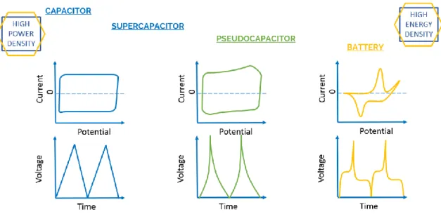
Fig. 1.5. Classification of the different electrochemical energy storage devices depending
on the electrochemical response of the electrode materials. ... 7
Fig. 1.6. Schematic representation of a capacitor configuration. ... 9 Fig. 1.7. Schematic representation of an electrochemical capacitor. ... 10 Fig. 1.8. Illustration exemplifying (a) redox pseudocapacitance and (b) intercalation
pseudocapacitance with their respective electrochemical fingerprints... 17
Fig. 1.9. (a) Example of a cyclic voltammetry profile of underpotential deposition of lead
adatoms on polycrystalline gold from HClO4 aqueous solution. (b) RuO2 in aqueous
0.1M H2SO4 as one of the most common examples of redox pseudocapacitance. Cyclic
voltammetry shows a series of positive electrode potentials (vs. RHE) at 50mV·s-1 exemplifying the squared nature of the pseudocapacitive response. (c) Cyclic voltammetry at different scan rates of Nb2O5 in 1M LiClO4 ... 18
Fig. 1.10. Results obtained for different manganese oxide allotropes ... 21 Fig. 1.11. Current strategies implemented in the development of next-generation super-
and pseudo-capacitors... 29
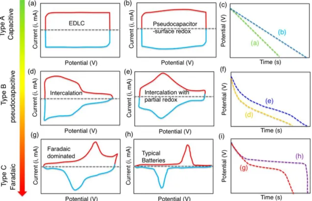
Fig. 1.12. Schematic representation of the representative cyclic voltammograms and
galvanostatic charge-discharge for energy storage materials with different charge storage mechanism.. ... 30
Fig. 1.13. Kinetic analysis of capacity contribution from outer surface response. The
y-intercept would correspond to the infinite sweep rate capacity... 32
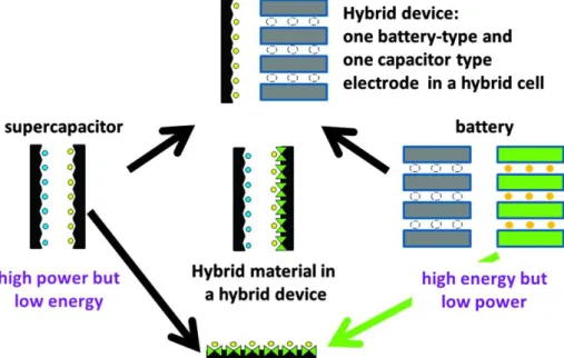
Fig. 1.14. Schematic representation exemplifying the hybridization approaches for the
combination of supercapacitor and battery-like responses though device configuration (Hybrid device) or though material engineering (Hybrid material) ... 32
Fig. 1.15. Representation of different morphologies and associated reported specific
capacitances for NiO ... 35
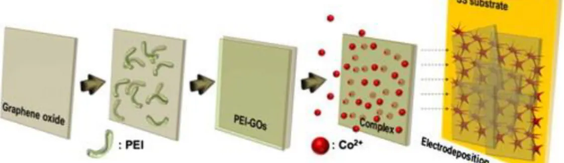
Fig. 1.16. Illustration of a synthesis process of reduced graphene oxide with nickel oxide
nanoparticles developed ... 38
Fig. 1.17. Schematic representation of the co-electrodeposition of cobalt oxide/graphene
composite material ... 42
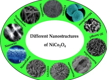
Fig. 1.18. Illustration of the different morphologies that have been reported for nickel
cobaltite ... 45
Fig. 1.19. Schematic representation of (a) Bode diagram with the phase transformations
during charge, discharge, overcharge and aging of Ni(OH)2 and (b) interslab distance
xviii
process. (d) Chemical ageing for phase conversion. (e) Hydrothermal synthesis and treatment. (f) Nickel metal oxidation. ... 51
Fig. 1.21. Electrochemical response evaluation by means of cyclic voltammetry at
100mV·s-1 in KOH 1M of exfoliated nanosheets by lactate route of (a) nickel-cobalt hydroxide, (b) nickel hydroxide, (c) cobalt hydroxide and (d) mixture 1:1 of nickel and cobalt nanosheets. The arrows indicate the evolution of the peaks with continuous cycling until stable response (red) after 40-50 cycles ... 54
Fig. 1.22. Schematic representation of the Co(OH)2/Graphene@Ni Foam symmetric
device, image of one of the electrodes (left) and SEM image of the coated foam at two different magnifications. ... 60
Fig. 1.23. Schematic illustration of the synthesis procedure undertaken to produce cobalt
hydroxide - Er-GO asymmetric supercapacitor. ... 60
Fig. 1.24. On the left there is the cyclic voltammetry of a) CRGO, b) Er-GO and c) GO
films on top of Au-PET substrates using 0.1M KCl as electrolyte and a scan rate of 50 mV s-1. On the right, the galvanostatic charge discharge curves of the Er-GO film in NaNO3 at the potential range of -0.1- 0.9V at a current density ranging from 84.86 to
212.16 A/g. ... 67
Fig. 1.25. Electrochemical characterization of Er-GO electrodeposited at -1.2V for 500s.
a) and b) Cyclic voltammetry at different scan rates. c) Galvanostatic charge discharge curves at different current densities. d) Specific capacity retention at different current densities. e) Capacity retention with continuous scan rate at 500 mV s-1 f) Nyquist plot of electrochemical impedance spectroscopy. ... 68
Fig. 2.1. Simplified representation of (a) the electrodeposition arrangement and (b-d) the
electrodeposition process for a nickel hydroxide film. ... 108
Fig. 2.2. a) Helmholtz double layer model of a double layer. b) Linear variation of
potential in the double layer with distance from the electrode. c) Stern model with d) its variation of potential based on the distance from the electrode. e) Triple-layer Grahame model... 110
Fig. 2.3. Variation of partial current densities (dashed line) and net current density (solid
line) with overpotential η... 111
Fig. 2.4. Potentitostatic current-time transient for the deposition of up to 5 individual
layers. This exemplifies 2D progressive nucleation with overlap. ... 113
Fig. 2.5. Theoretical potentiostatic current-time transient, including the effect of overlap.
... 114
Fig. 2.6. Schematic cross section of a columnar deposit. ... 114 Fig. 2.7. Representation of the different structures of electrodeposited thin films. ... 115 Fig. 2.8. (a) Scheme of galvanostatic current (constant current) applied in a given time.
(b) Variation of potential of the electrode with time when a constant current is applied. (c) Equivalent circuit for a single-electrode reaction taking into consideration the double-layer capacitance and the charge transfer resistance. ... 116
Fig. 2.9. Scheme comparing cathodic electrodeposition versus anodic electrodeposition.
xix
Fig. 2.12. Linear potential sweep voltammetry comparison for the input and output
responses ... 118
Fig 2.13. Exemplification scheme of the exfoliation of graphene into Er-GO via
intercalation of Li+ ions ... 120
Fig. 2.14. a) Cyclic voltammogram showing the evolution of graphene oxide in 0.1M
Na2SO4 at 50 mV s-1in the reduction process. b) Specific capacitance measured with
the evolution of the reduction cycles, measured in the range 0-0.9V vs RHE at 20 mV s-1 ... 123
Fig. 2.15 Deposition behaviour of graphene oxide suspension (0.5 g L-1) with NaCl 0.25M for optimum conductivity at different pH values. Deposited were obtained in a pH range from 1.5 to 12.5 at a potentiostatic deposition performed at -1.2V vs. SCE .. 126
Fig. 2.16. Cyclic voltammetry curves for the electrochemical investigation of Er-GO and
variations with scan rate for the Er-GO electrochemistry ... 127
Fig. 2.17. (a) Variation of mass vs. time for 0.2M Ni(NO3)2, 2.0M Ni(NO3)2 and 0.2M
Ni(NO3)2 saturated with NaNO3. (b) Mass vs. time for deposition of 2.0M Ni(NO3)2 in
basified conditions. (c) Mass vs. time at 0.1 mA in diluted Ni(NO3)2 solutions (<0.2M).
... 130
Fig. 2.18. Effect of (a) nickel concentration, (b) nitrate concentration and (c) temperature
in the current efficiency and density of nickel hydroxide electrodeposited films .... 131
Fig. 2.19. Morphological variations caused by different electrodeposition modes for
cobalt hydroxide ... 133
Fig. 2.20. Morphology of cobalt hydroxide electrodeposited at (A), (B) 0.65V, (C),(D)
-0.75V and (E), (F) -0.85V at 50oC from cobalt nitrates in aqueous electrolyte containing 50% in weight of surfactant Brij 56 ... 134
Fig. 2.21. Illustration of the different groups of 2D nanomaterials whose delamination is
currently under investigation ... 138
Fig. 2.22. Schematic representation the exfoliation process undergone and the
corresponding materials’ structures. (a) Representation of a hydroxide material with d1
as interlayer distance. (b) LDHs structure with inter-slab anions and water molecules. (c) Exfoliated LDH monolayers in colloidal suspension. Each layer corresponds to edge-sharing octahedral MO6 unities where M denotes a metal element. (d)
Transmission electron microscopy image of bulk LDH Ni-Co material. (e) Transmission electron microscopy image of single-layer exfoliated Ni-Co LDH ... 141
Fig. 2.23. Interlamellar expansion process for nickel oxide ... 143 Fig. 2.24. Exfoliation and restacking procedure scheme ... 144 Fig. 2.25. (a) AFM image of [CoO2]- nanosheets dropcasted from the exfoliated
suspension onto mica substrate with the correspondent height profile revealing the presence of individual sheets with 0.35 nm thickness and (b) a bright-field HRTEM image of the cobalt oxide nanosheets revealing hexagonal closed-packed arrangement of cobalt atoms. ... 145
Fig. 2.26. Schematic illustration of the resulting structures after exfoliation, combination
xx
over Stainless Steel. ... 173
Fig. 3.1.2. High-Resolution and fine structure Transmission Electron Microscopy
(HR-TEM) images of (a) Ni-Co(OH)2 (2:1), (b) Ni-Co(OH)2 (1:2), (c) Ni-Co(OH)2/Er-GO
(2:1) and (d) Ni-Co(OH)2/Er-GO (1:2). ... 174
Fig. 3.1.3. Elemental mapping of Carbon, Oxygen, Cobalt and Nickel detected by EDS
analysis for (a) Ni-Co(OH)2 (2:1) and (b) Ni-Co(OH)2/Er-GO (2:1). ... 175
Fig. 3.1.4. Elemental mapping of Carbon, Oxygen, Cobalt and Nickel detected by EDS
analysis for (a) Ni-Co(OH)2 (1:2) and (b) Ni-Co(OH)2/Er-GO (1:2). ... 176
Fig. 3.1.5. Example of the area considered for semi-quantitative analysis calculation by
means of XPS for Ni2p3 and Co2p3 for Ni-Co(OH)2(2:1). Analogous fittings and
calculations were performed for Ni-Co(OH)2(2:1) /Er-GO, Ni-Co(OH)2(1:2) and
Ni-Co(OH)2(1:2) /Er-GO. ... 178
Fig. 3.1.6. Comparative GIXD results for the samples (a) Ni-Co(OH)2(1:2)2 and
Ni-Co(OH)2(1:2)/Er-GO (b) Ni-Co(OH)2(2:1) and Ni-Co(OH)2(2:1)/Er-GO. ... 180
Fig. 3.1.7. Raman Spectra for (a) Ni-Co(OH)2(1:2) and Ni-Co(OH)2(1:2)/Er-GO and (b)
Ni-Co(OH)2(2:1) and Ni-Co(OH)2(2:1)/Er-GO Electrodeposited on Stainless Steel.
... 181
Fig. 3.1.8. Raman Spectra comparison of dropcasted graphene oxide and
electrochemically reduced graphene oxide... 183
Fig. 3.1.9. (a) Cyclic Voltammetry comparison at 50 mV/s and (b) Galvanostatic Charge
Discharge comparison at 1A/g. ... 184
Fig. 3.1.10. Cyclic Voltammetry at different scan rates and Galvanostatic
Charge-Discharge Curves at different current densities for (a,b) Ni-Co(OH)2(2:1) and (c,d)
Ni-Co(OH)2(2:1)/Er-GO. ... 187
Fig. 3.1.11. Cyclic Voltammetry at different scan rates and Galvanostatic
Charge-Discharge Curves at different current densities for (a,b) Ni-Co(OH)2(1:2) and (c,d)
Ni-Co(OH)2(1:2)/Er-GO. ... 188
Fig. 3.1.12. Capacity Retention for different Current Densities for the Ni-Co(OH)2 and
Ni-Co(OH)2/Er-GO composite materials. ... 189
Fig. 3.1.13. Capacity Retention comparison at 10A/g for Ni(OH)2, Co(OH)2, Ni-Co(OH)2
(1:2), Ni-Co(OH)2 (1:2)/Er-GO, Ni-Co(OH)2 (2:1) and Ni-Co(OH)2 (2:1)/Er-GO. 190
Fig. 3.1.14. Cyclic Voltammetry response degradation with cycling for the samples (a)
Ni-Co(OH)2 (2:1) and (b) Ni-Co(OH)2(2:1)/Er-GO composite materials. ... 191
Fig. 3.1.15. (a-b) Bode and (c-d) Nyquist Electrochemical Impedance Spectra of Co(OH)2
, Ni(OH)2, Ni-Co(OH)2(1:2), Ni-Co(OH)2(1:2)/Er-GO, Ni-Co(OH)2(2:1) and
Ni-Co(OH)2(2:1)/Er-GO composite materials. ... 192
Fig. 3.1.16. (a-b) Bode and (c-d) Nyquist Electrochemical Impedance Spectra of the
Ni-Co(OH)2(1:2) and Ni-Co(OH)2(1:2)/Er-GO composite materials at 0, 750 and 5000
cycles of Galvanostatic Charge Discharge at 10 A/g for both discharged (left) and charged (right) potentials of the sample. ... 193
xxi discharge process. ... 194
Fig. 3.1.18. Representation of the reactions in a Ni-Co(OH)2 /Er-GO film in KOH 1M
electrolyte ... 195
Fig. 3.1.19. Scanning Electron Microscopy images of the samples (a), (b) Ni-Co(OH)2
(1:2) and (c), (d) Ni-Co(OH)2/Er-GO before and after cycling. ... 197
Fig. 3.2.1. Scanning Electron Microscopy image of (a) Ni-Co(OH)2 (1:2). ... 212
Fig. 3.2.2. Cyclic Voltammetry at 50 mV·s-1 plot for Ni-Co(OH)2 (1:2) ... 213
Fig. 3.2.3 Bode (a-b) and Nyquist plots, at different magnifications, (c.1 - c.2) of
Impedance Spectroscopy for Ni-Co(OH)2 (1:2) at discharged (-0.2V), intermediate
charge (0.1V) and charged condition (0.4V) of the sample. (d) EIS Equivalent circuit employed to fit the variation of impedance spectra obtained for Ni-Co(OH)2 (1:2) in
the charge process. ... 215
Fig. 3.2.4. Schottky at 1000Hz (blue) and fitting of the linear region of the
Mott-Schottky plots (red) of Ni-Co(OH)2 (1:2). ... 217
Fig. 3.2.5. Electronic and Phase model of the Charging process of Nickel-Cobalt
hydroxide based on the current density (cyclic voltammetry) and charge-space capacitance (Mott-Schottky) as a function of the applied potential. (a) Illustration of the band bend occurring when the Fermi level of the semiconductor is placed higher than that of the electrolyte for a p-type semiconductor. (b) Illustration of the equilibrium state of bands when the Fermi level of the semiconductor is the same of the electrolyte. (c) Illustration of the band bend happening when the Fermi level of the semiconductor is placed lower than that of the electrolyte for a p-type semiconductor. (d-e) Phase transformations occurring during the charging process for the Ni-Co double hydroxide materials. ... 220
Fig. 3.3.1. Physico-chemical characterization of the surface film: a) Scanning Electron
Microscopy image. b) Transmission Electron Microscopy with diffraction rings inset.
c) XRD Spectra and d) Raman Spectra of NixCo1-x(OH)2. ... 232
Fig. 3.3.2. Geometry of the analyzed samples used in the set-up: Stainless steel substrate
embedded in epoxy ... 233
Fig. 3.3.3. Cyclic voltammetry at: a) 5 mV·s-1 and b) 3 mV·s-1 and their expanded version in time c) and d) with the corresponding measurements of pH and dissolved O2 content
variation measured in-situ within a potential range from -0.2V to 1.1V in K2SO4 0.05M.
... 234
Fig. 3.3.4. Cyclic voltammetry at: a) 5 mV·s-1and b) 3 mV·s-1 and their expanded version in time c) and d) with the corresponding in-situ measurements of pNa within a potential ranging from -0.3V to 1.1V in Na2SO4 0.05M. ... 235
Fig. 3.3.5. Schematic representation of the processes occurring during
oxidation-reduction of NixCo1-x(OH)2 in K2SO4/ Na2SO4 0.05M... 241
Fig. 3.4.1. SEM images of (a) NCOx obtained with an upper-electrons detector (UED), (b) and a compositional detector (COMPO). (c) NCOx/Er-GO obtained with an UED
xxii
combination with Er-GO, for the same nickel:cobalt ratio, included for comparison purposes. ... 255
Fig. 3.4.3. Low magnification TEM images of (a) NCOx and (b) NCOx/Er-GO.
HR-TEM images of (c) NCOx and (d) NCOx/Er-GO. ... 256
Fig. 3.4.4. Transmission electron microscopy image of (a) Ni-Co oxide material on top
of electrochemically graphene oxide and (b) the corresponding FFT image of the area. ... 257
Fig. 3.4.5. Electron diffraction spectroscopy mapping for the elements Carbon (blue),
Oxygen (red), Cobalt (yellow) and Nickel (green) for the composites (a) Ni-Co oxide and (b) Ni-Co oxide on top of an electrochemically reduced graphene oxide flake. 259
Fig. 3.4.6. X-ray photoelectron spectroscopy results for the elements Carbon 1s, Oxygen
1s, Nickel 2p3 and Cobalt 2p3 for the composites (a) NCOx and (b) NCOx/Er-GO. ... 260
Fig. 3.4.7. Raman spectra for (a) NCOx and (b) NCOx/Er-GO. ... 262 Fig. 3.4.8. Raman spectra comparison for the signal obtained for (a) dropcasted graphene
oxide with no electrochemical reduction, (b) graphene oxide after electrochemical reduction, (c) graphene oxide in the composite material after electrochemical reduction and thermal treatment, (d) pure GO thin-film after thermal treatment. ... 265
Fig. 3.4.9. Cyclic Voltammetry and Galvanostatic charge-discharge results comparison
at 50 mV/s and 1A/g respectively for (a) NCOx and (b) NCOx/Er-GO measured in KOH 1M. ... 267
Fig. 3.4.10. Cyclic Voltammetry for (a) NCOx and (c) NCOx/Er-GO at scan rates from
10-500 mV·s-1 and Galvanostatic Charge-Discharge Curves at current densities from 1-10 A·g-1 for (b) NCOx and (d) NCOx/Er-GO measured in KOH 1M. ... 268
Fig. 3.4.11. Capacity Retention comparison obtained during cycling at 8 A·g-1 during 5000 cycles measured in KOH 1M. ... 270
Fig. 3.4.12. Scanning electron microscopy images showing the degradation effects in the
initial composites (a) NCOx and (c) NCOx/Er-GO after 5000 cycles of charge-discharge at a current density of 8 A/g for (b) NCOx and (d) NCOx/Er-GO. ... 271
Fig. 3.4.13. Cyclic Voltammetry response degradation at 50 mV·s-1 with cycling for (a) NCOx and (b) NCOx/Er-GO measured in KOH 1M. ... 272
Fig. 3.4.14. Electrochemical impedance spectra comparison for electrodeposited Ni-Co
oxide and Ni-Co oxide measured in KOH 1M in combination with electrochemically reduced graphene oxide in the form of (a) impedance modulus versus frequency (b) phase angle versus frequency and (c) Nyquist plots obtained at two different potentials, namely -0.2V, discharged condition, and 0.45V, charged condition. ... 274
Fig. 3.4.15. (a) and (b) Bode and (c) Nyquist Electrochemical Impedance Spectra for
NCOx composite material after 0, 150, 750, 1500 and 5000 cycles of Galvanostatic Charge Discharge at 8 A/g for both discharged (-0.2V, left) and charged (0.45V, right) potentials. ... 275
Fig. 3.4.16. (a) and (b) Bode and (c) Nyquist Electrochemical Impedance Spectra for
xxiii
Fig. 3.4.17. (a) General equivalent circuit model used in the fitting of the impedance
spectra acquired for NCOx and NCOx/Er-GO for the results obtained at -0.2V (discharged) and 0.45V (charged) and (b) Equivalent circuit model used in the fitting of impedance spectra acquired for NCOx/Er-GO at -0.2V with cycling after 750, 1500 and 5000 cycles. ... 278
Fig. 3.4.18. Graphic analysis of the results obtained for the fitting of EIS spectra. .... 279 Fig. 3.5.1. Diagram of the delamination process undertaken for nickel-cobalt hydroxide.
... 291
Fig. 3.5.2. Schematic of the exfoliation process for γ-NixCo1-xO2 nanoslabs. ... 293
Fig. 3.5.3. X-Ray Diffraction patterns for (a) NCOH taken as reference material, (b)
SDS-NCOH, (c) Lac-NCOH and (d) NCOH-DIAL after exfoliation in H2O and re-stacking
by dialysis. Numbers indicate the inter-reticular distances for each assigned peak, they are deduced by indexation with a hexagonal cell. ... 297
Fig. 3.5.4 Scanning Electron Microscopy images of (a) DS-NCOH, (b) Lac-NCOH and
(c) restacked nickel-cobalt hydroxide nanoslabs by dialysis after exfoliation in distilled water (NCOH-DIAL). ... 298
Fig. 3.5.5 Transmission Electron Microscopy images of (a) DS-NCOH, (b) Lac-NCOH,
(c) delaminated nanoslabs of lactate intercalated Ni-Co(OH)2 in distilled water and (d)
restacked nanoslabs of delaminated Ni-Co(OH)2 slabs obtained by dialysis
(NCOH-DIAL). ... 299
Fig. 3.5.6. HR-TEM images of delaminated lactate-intercalated nickel-cobalt hydroxide
in distilled water. ... 300
Fig. 3.5.7. Fourier-transform infrared spectroscopy results for (a) NCOH taken as
reference material, (b) SDS-NCOH, (c) Lac-NCOH and (d) NCOH-DIAL after exfoliation in H2O and re-stacking by dialysis. ... 301
Fig. 3.5.8. Detail of the 400-1390 cm-1 section of FTIR spectra for the materials obtained during the delamination of nickel-cobalt hydroxide by lactate intercalation. ... 301
Fig. 3.5.9. Raman results for (a) NCOH taken as reference material, (b) SDS-NCOH, (c)
Lac-NCOH and (d) NCOH-DIAL after exfoliation in H2O and re-stacking by dialysis
from 300-1600 cm-1 and from 2600 to 3500 cm-1. ... 302
Fig. 3.5.10. Detail of the 1000-1500 cm-1 section of Raman spectra for the materials obtained during the delamination of nickel-cobalt hydroxide by lactate intercalation. ... 303
Fig. 3.5.11. BET adsorption-desorption isotherm results for Lac-NCOH. ... 304 Fig. 3.5.12. Atomic force microscopy topography (a) 2D image, (b) 3D image, and (c)
height profiles of delaminated lactate-intercalated nickel-cobalt hydroxide obtained in tapping-mode. Each dotted line corresponds to a height profile with the same numeration (d) schematic representation of theoretic values for a nickel-cobalt oxyhydroxide bilayer. ... 305
Fig. 3.5.13. X-Ray Diffraction results for (a) NCOH, (b) NCOx-HNK, (c) NCOx-H and
(d) restacked NCOx-TBA. The numbers correspond to the inter-reticular distances calculated on the basis of indexation with a hexagonal cell. ... 307
xxiv
... 308
Fig. 3.5.15. Transmission Electron Microscopy images of (a) NCOx-HNK and (b)
exfoliated oxide slabs in TBAOH (NCOx-TBA). ... 309
Fig. 3.5.16. FTIR results for (a) NCOH, (b) NCOx-HNK, (c) NCOx-H and (d) restacked
NCOx-TBA. ... 310
Fig. 3.5.17. Raman results for (a) NCOH, (b) NCOx-HNK, (c) NCOx-H and (d) restacked
NCOx-TBA. ... 311
Fig. 3.5.18. BET adsorption-desorption isotherm results for NCOx-H. ... 312 Fig. 3.5.19. BET adsorption-desorption isotherm results for NCOx-TBA ... 312 Fig. 3.5.20. Atomic force microscopy topography (a) 2D image, (b) 3D image, and (c)
height profiles of delaminated tetrabutylammonium-intercalated nickel-cobalt oxyhydroxide obtained in tapping-mode. Each dotted line corresponds to a height profile with the same numeration, (d) schematic representation of theoretic values for a nickel-cobalt oxyhydroxide bilayer. ... 313
Fig. 3.5.21. Exemplification of the evolution of the discharge curves during the activation
process for DS-intercalated nickel-cobalt hydroxide (DS-NCOH) measured at 1A·g-1
in 1M KOH. ... 314
Fig. 3.5.22. Comparison of the electrochemical response by (a) cyclic voltammetry, (b)
galvanostatic discharge, (c) capacity at different applied current densities and (d) capacity evaluated by galvanostatic continuous charge-discharge cycling during 5000 cycles at 4 A·g-1 for the different composites obtained during delamination by lactates route of nickel-cobalt hydroxide in 1M KOH. ... 315
Fig. 3.5.23. Cyclic voltammetries at different scan rates and galvanostatic discharge
curves at different applied current densities for the materials obtained during the delamination of nickel-cobalt hydroxide by lactate intercalation evaluated in 1M KOH. ... 317
Fig. 3.5.24. Comparison of the electrochemical response by (a) cyclic voltammetry, (b)
galvanostatic discharge, (c) capacity at different applied current densities and (d) capacity evaluated by galvanostatic continuous charge-discharge cycling during 5000 cycles at 4 A·g-1 for the different composites obtained during delamination by lactates route of nickel-cobalt hydroxide in 1M LiOH. ... 318
Fig. 3.5.25. Cyclic voltammetries at different scan rates and galvanostatic discharge
curves at different applied current densities for the materials obtained during the delamination of nickel-cobalt hydroxide by lactate intercalation evaluated in 1M LiOH. ... 319
Fig. 3.5.26. Comparison of the electrochemical response by (a) cyclic voltammetry, (b)
galvanostatic discharge, (c) capacity retention at different applied current densities and (d) capacity retention evaluated by galvanostatic continuous charge-discharge cycling during 5000 cycles at 10 A·g-1 for the different composites obtained during delamination of nickel-cobalt oxyhydroxide by TBA+ intercalation in 1M KOH. .. 321
Fig. 3.5.27. Capacity evolution during the first 200 cycles of the materials obtained during
xxv delamination of nickel-cobalt oxyhydroxide by tetrabutylammonium intercalation evaluated in 1M KOH. ... 323
Fig. 3.5.29. Comparison of the electrochemical response by (a) cyclic voltammetry, (b)
galvanostatic discharge, (c) capacity retention at different applied current densities and (d) capacity retention evaluated by galvanostatic continuous charge-discharge cycling during 5000 cycles at 10 A·g-1 for the different composites obtained during
delamination of nickel-cobalt oxyhydroxide by TBA+ intercalation in 1M LiOH .. 324
Fig. 3.5.30. Cyclic voltammetries at different scan rates and galvanostatic discharge
curves at different applied current densities for the materials obtained during the delamination of nickel-cobalt oxyhydroxide by tetrabutylammonium intercalation evaluated in 1M LiOH. ... 326
Fig. 4.1. (a) Galvanostatic discharge curves of nickel-cobalt (i) hydroxide and (ii) oxide
with (b) their corresponding SEM images ... 337
Fig. 4.2. Schematic representation of the main degradation phenomena reported in this
thesis, exemplified in an α phase of nickel-cobalt hydroxide. ... 338
Fig. 4.3. (a) Galvanostatic discharge curves of nickel-cobalt (i) hydroxide and (ii)
xxvii
Table 1.1
Comparison of the average capacitance values displayed by different carbon forms.14
Table 1.2
Summary of some of the reported morphologies for nickel oxide together with their synthesis route and capacity values. ... 36
Table 1.3
Summary of some of the reported morphologies for cobalt oxide together with their synthesis route and capacity values. ... 40
Table 1.4.
Electrochemical performance of cobalt oxide materials used as electrodes for lithium ion batteries. ... 43
Table 1.5
Summary of some reported work on the synthesis of NiCo2O4 and their electrochemical
performance as electrode material in alkali media. ... 46
Table 1.6
Brief summary of the displayed properties for the main commercial nickel-based batteries. ... 49
Table 1.7
Summary of some of the results obtained for nickel hydroxide with different morphologies prepared by different synthesis strategies. ... 53
Table 1.8
Summary of some representative work obtained for cobalt hydroxide prepared by different synthesis strategies with different morphologies. ... 57
Table 1.9
Summary exemplifying the complementary properties that graphene derivatives and metal oxides have and how, by creating a composite material, synergistic effects coming from the interaction can be achieved. ... 70
Table 2.1.
Summary of experimental conditions used in the production of electrochemically exfoliated graphene oxide nanosheets. ... 120
Table 2.2
Summary of experimental conditions for the electrochemical reduction of pre-deposited GO layers. ... 125
Table 2.3.
Summary of some of the main work concerning electrodeposition of cobalt hydroxide presented in literature ... 136
Table 3.1.1
Semi-quantitative mass percentage results obtained by means of Energy Dispersive X-Ray Spectroscopy (EDS) for the electrodeposited samples. ... 177
xxviii
Semi-quantitative atomic percentages with their corresponding errors obtained by means of X-Ray Photoelectron Spectroscopy for the samples Ni-Co(OH)2(2:1),
Ni-Co(OH)2(2:1)/Er-GO, Ni-Co(OH)2(1:2) and Ni-Co(OH)2(1:2)/Er-GO. ... 177
Table 3.1.3
Capacity values for different current densities for Ni-Co(OH)2/Er-GO composite
materials. ... 189
Table 3.1.4
Fitting results for the equivalent circuits shown in Fig. 3.1.17 for the impedance spectroscopy done in Ni-Co(OH)2 electrodeposited layers. ... 199
Table 3.2.1.
Values obtained for the fitting results of the impedance spectra of Ni-Co(OH)2 (1:2)
according to the equivalent circuits presented in Fig. 3.2.3 ... 216
Table 3.4.1
X-ray photoelectron spectroscopy comparison for the fitted results obtained for the nickel-cobalt oxide and the nickel-cobalt oxide combined with electrochemically reduced graphene oxide composites ... 263
Table 3.4.2
Values of capacity calculated at current densities ranging from 1 to 10 A·g-1 for NCOx and NCOx/Er-GO. ... 269
Table 3.5.1
Chemical analysis for the materials obtained during the delamination of nickel-cobalt hydroxide by lactate intercalation in weight percentage and their molar ratio in relation to nickel and cobalt content. ... 297
Table 3.5.2
Chemical analysis for the materials obtained during the delamination of nickel-cobalt oxyhydroxide by tetrabutylammonium intercalation in weight percentage ... 308
Table 4.1
Summary of the main results obtained for the different materials synthesized and presented in the course of this manuscript... 342
xxix
V. Abbreviations and Acronyms
AFM Atomic force microscopy
BET Brunauer-Emmett-Teller
CP Conductive polymer
CPE Constant phase element
CQD Carbon quantum dots
CTAB Cetrimonium bromide
CV Cyclic voltammetry
CVD Chemical vapour deposition
ED Electrodeposition
EDS Energy Dispersive X-Ray Spectroscopy
EFB Flatband potential
EIS Electrochemical impedance spectroscopy
EQCM Electrochemical quartz cristal microbalance
Er-GO Electrochemically reduced graphene oxide
ESD Energy storage devices
FEG-SEM Field-emission gun scanning electron microscopy
FTIR Fourier-transform infrared spectroscopy
GCD Galvanostatic charge-discharge
GIXD Grazing-Incidence X-Ray Diffraction
GO Graphene Oxide
HOPG Highly-oriented pyrolytic graphite
HER Hydrogen evolution reaction
HMT Hexamethylenetetramine
HOPG Highly oriented pyrolytic graphite
HR-TEM High-resolution transmission electron microscopy
LDH Layered double hydroxide
MWCNT Multi-wall carbon nanotube
OER Oxygen evolution reaction
PANI Polyaniline
PEDOT Poly(3,4-ethylenedioxythiophene)
PPy Polypyrrol
PS Polystirene
PTFE Polytetrafluoroethylene
rGO Reduced graphene oxide
SAED Selected area electron diffraction
SCE Saturated calomel electrode
SDS Sodium dodecyl sulphate
SIET Selective ion electrode technique
SSD Solid-state diffusion
TBAOH Tetrabutyl ammonium hydroxide
TMAOH Tetramethyl ammonium hydroxide
XPS X-ray photoelectron spectroscopy
3
1. Materials for Electrochemical Energy Storage
The United Nations has pin-pointed climate change as one of the eighteen global issues of biggest concern in the world, and energy as one of humanity top problems for the next century. As a consequence, more than 3000 international environmental agreements have been developed to raise awareness and shift towards a more sustainable growth [1]. Our lifestyle is sustained by energy production and consumption. However, up to an 80% of the energy production derives from the combustion of fossil fuels, which leads to the formation of CO2, the main driver of climate change [2]. Another big concern is the
depletion of those fossil fuels. According to the U.S. Energy Information Administration, there has been an overconsumption of energy during approximately the last 60 years, as seen in Fig. 1.1. In fact, the main sources used to produce energy are coal, natural gas and crude oil [3], all non-renewable sources.
Fig.1.1. (a) World Energy Consumption and Production and (b) Source of Energy
production overview from 1949 to 2016. Data extracted with copyright permission of the U.S. Energy Information Administration [3].
Thus, to ensure a sustainable development, an energy transition is required. Humanity shall reduce their petroleum, natural gas and coal energy consumption and transition into renewable sources of energy, including geothermal, solar, wind, biomass and hydroelectric. However, there is a major issue concerning renewable energy sources and their production intermittency [4]. Nonetheless, there are three more aspects to sustainable energy usage that shall be optimized apart from production, namely; transport, conversion and storage.
In particular, energy storage plays a key role in the transition to low-carbon economies. Fully-functional energy storage reservoirs that can deliver reliable power to an ever-growing society (Fig. 1b) are crucial [5].To comply with the European Union policy goals for 2030, an increase in the electrification of the energy system is expected. In the past, due to the existence of daily consumption cycles of electricity, mainly based on fossil fuels, nuclear energy and hydrothermal production, the need of variability in the energy production was not relevant. As a consequence, the necessity for energy storage was limited. It is reported that in 2014 the total amount of electricity stored was estimated to 171 GW, a 2% of the total generation. However, energy consumption patterns have been changing relatively fast; nowadays there is an increased demand of energy in electric form and energy for operative off-grid technologies [6].
4
Regarding the delivery of electricity, smart grids and flexible generation are required for a successful societal development. Smart grids are electrical grids in which appliances and metrics are employed, such as renewable and efficient energy resources; being
conditioning and control of the production and distribution of the electric power two of
their most important characteristics [7,8]. An adequate amount of energy can only be efficiently supplied if the corresponding energy storage system has the properties to satisfactory perform that task. For that reason, optimized energy storage systems shall be developed.
Moreover, it is well known that many recent technologic developments rely on mobile energy storage suppliers. Devices such as laptops or mobile phones need to be transported. Most of the devices are not designed to require a constant supply of electricity but to be independent from the general grid. Thus, another risen challenge to consider is how to tailor the properties of an energy storage device so it can comply with the energetic demand of a particular application. Therefore, there is an increasing need to improve the current ability to store energy. If we are unable to capture, manage and store energy efficiently, the only alternative, but unlikely solution, would be to reduce energy consumption [9].
For that reason, different energy storage systems have been developed and are under constant improvement. All the energy storage systems developed so far can be classified in five different groups: mechanical, thermal, chemical, electrochemical and electrical. Fig. 1.2 demonstrates a more accurate categorization of energy storage systems.
Fig. 1.2. Scientific categorization of Electrical Energy storage systems. CAES stands
for Compressed Air Energy Storage; LAES for Liquid Air Energy Storage; SNG for Synthetic Natural Gas. Note that this list is representative of the major electrical energy
storage systems and may not include all of them. Diagram extracted and modified with copyright permission of the E-Storage report on World Energy Resources by the World
Energy Council [10]. Electric Energy Storage Systems Thermal Thermo-Chemmical Sensible Thermal Latent Thermal Mechanical Pump-storage hydropower CAES LAES Flywheels Chemical Hydrogen Storage SNG Electrochemical Li-ion batteries Na-ion batteries Lead Acid Batteries Metal Air Batteries Redox Flow Batteries Hybrid devices Fuel Cells Electrical Supercapacitors Capacitors
5 Depending on the duration and the frequency of the power supply required by an application, different energy storage systems may be used. For example, in applications that require seconds to minutes of power supplies, batteries, supercapacitors or flywheels may be used; whereas for slightly longer periods of times, this is daily usage, batteries, pump hydropower, CAES/LAES, thermochemical or redox flow batteries would be used [10]. This is exemplified in Fig. 1.3.
Fig.1.3. Diagram exemplifying the type of suitable applications for an energy storage
device according to the power and energy required. Reprinted with Copyright permission from Clarke et al. [11]
Regarding mechanical systems, pumped hydro-energy storage has been dominating the energy storage market for over a century. It simply consists on generating electricity by moving water between two water tanks at different levels. Compressed air energy storage uses off-peak electricity to compress air in geological structures that is released to drive a turbine when energy is required. Liquid air energy storage is similar, but the air is compressed and cooled in refrigeration plants. Finally, flywheels store kinetic energy in rotating discs that are suspended on magnetic bearings [10]. However, although mechanical systems are able to bridge short imbalances in energy demand, they are quickly depleted [12].
Thermal systems are classified in three different groups depending on their fundamental principles. Thermochemical are based on reversible temperature-dependent chemical reactions such as sorption-based reactions. Latent thermal storage is based on phase transitions. Sensible thermal storage is based on materials with very high thermal capacities. Thermal storage applications are, unfortunately, very limited [10].
Concerning chemical energy storage, energy can be stored in the form of hydrogen or synthetic natural gas, also called “power gas” technologies, which consist of water splitting followed by the reaction of carbon dioxide with hydrogen by means of an electrolyser to produce synthetic methane [13].
This suite of diverse technologies is constantly evolving, and new energy storage systems are continuously being developed. In fact, exhaustive research is being done on all of the different energy storage systems presented. Nonetheless, it is of particular interest to further develop electrochemical and chemical energy storage devices. Although it is an
6
outdated non-environmentally-friendly technology, lead-acid batteries dominated the market from 1990 to 2015, accounting for a 90% of the total market [14]. Storage in commercial batteries currently fail to reach the required energy storage densities required for the energy reservoirs to supply the whole economy [12]. For that reason, a great focus of research is being done in the field of electrochemical energy storage, impulsed by the tremendous growth of the battery demand during the last decade, as shown in fig. 1.4 [15].
Fig. 1.4. (a) Growth of the market demand for Lithium-ion batteries, reproduced from
Lithium-Ion batteries: Advances and applications, edited by Gianfranco Pistoia [15]. (b) Partition of the technology share that each energy system has exemplifying the diversity of different battery research being conducted. Image obtained with copyright permission
from Aneke et al. [16].
In the pursuit of refined and efficient energy storage systems with tailored properties, many different electrochemical and electrical energy storage systems and combinations thereof have been developed. The fundamental principles of electrochemical energy storage systems and electrical systems shall be understood and are discussed and compared in the following section.
7
Electrochemical Energy Storage
As aforementioned, there is an increased interest in tailoring the properties of energy storage devices (ESD) for specific applications. Among the different energy storage devices, a possible approach towards optimised energy usage is the study of electrochemical and electrical systems.
On one hand, electrical energy storage devices are divided into two main groups, capacitors and supercapacitors. On the other hand, fuel cells and batteries integrate the group of electrochemical ESDs. However, in the development of new energetic solutions, novel electrochemical responses and device configurations are achieved that have intermediate outcomes. For that reason, the division between the two, although clear in their fundamental principles, is not always straightforward when a system response is evaluated. For that reason, an overview to the different ESDs configurations is here introduced.
Furthermore, any given technology has some features that makes it suitable for a specific application. These features determine the best technology to be adopted and shall also be evaluated to understand the extent to which the commercially available devices are different. The properties that determine the functional units of an energy storage system are: energy density and power density, life time, capital and operating costs, storage capacity and duration, round trip efficiency (defined as the “ratio of electricity output from the storage device to the electricity input to the device during one charge/discharge cycle”) and response time [16].
Nowadays, given the different electrochemical responses, this type of energy storage systems can be classified in four groups, as shown in figure 1.5, namely; capacitors, supercapacitors, pseudocapacitors or redox supercapacitors and batteries. Note that fuel-cells are not considered since they are out of the scope of the present work. Moreover, because of the extensive work performed in this topic, only an overview of the main materials and not an in-depth review of all the materials involved in electrochemical energy storage is provided.
Fig. 1.5. Classification of the different electrochemical energy storage devices
depending on the electrochemical response of the electrode materials.
It is worth delimiting the scope of the present work. Many aspects of electrochemical energy storage devices have not been included, such as some less explored materials and
8
composites, different current collectors, an exhaustive review on electrolytes used or an exhaustive study of different synthesis techniques. For example, metal-organic frameworks, quantum dots, nitride-based composites and composites based on organic active materials, beyond conductive polymers, are fascinating fields of study in the field of super- and pseudocapacitive energy storage that have not been included. Some information can be found in the appropriate literature such as the review of Aurback et al. [17] or the review by Wu et al., which summarizes the latest developments in electrode materials for super- and pseudocapacitors [18]. In the same manner, there are appropriate reviews in most of the major components of energy storage devices. This chapter is only intended to provide a review on the state-of-the-art and major developments in the field of materials for energy storage with emphasis in nickel oxides and hydroxide, cobalt oxide and hydroxide, graphene-based materials and combination thereof.
9
1.1 Capacitors
Capacitors, also known as electrostatic capacitors, store electricity by means of charge separation. They are usually made of two parallel metal electrodes that are separated by a dielectric material. The dielectric material acts as an insulator preventing the recombination of both charges. This configuration is shown in Fig. 1.6.
The accumulated charge at the electrode interface comes from two different possible sources. It is either the result of an excess or deficit of conduction-band electrons at the surface (or near-surface) regions of the active material or from the counterbalancing of charge densities accumulated on the electrode-electrolyte interface [19].
The unit for the energy stored in a capacitor is capacitance. Capacitance is mathematically described by the ratio between the positive, or negative, charge stored at each plate and the voltage applied between them, as expressed by equation 1.1:
𝐶 =𝑄
𝑉 (𝑒𝑞. 1.1)
The dielectric plays a key role in the performance of the capacitor since the operating voltage greatly depends upon its strength. Then, the dielectric strength is defined as the maximum electric field that can exist in the dielectric without electrical breakdown. Capacitance is measured in Farads (F), which is the ratio between coulombs (Q) and volts per metre (V/m) [20] and traditional capacitors are at the order of microfarads.
Fig. 1.6. Schematic representation of a capacitor configuration.
The application of capacitors goes from backup circuits of microcomputers to smoothing circuits in power supplies and DC blocking in signal filtering. These applications do not require much energy but depend on fast charge-discharge [21].
Traditional capacitors are usually composed of two metallic plates, traditionally based on aluminium, tantalum or ceramic materials, with a solid electrolyte used to separate two identical electrodes [21]. The non-conductive dielectric is usually glass, ceramic, plastic film, paper, mica or oxide layers. Electrolytic capacitors are a form of capacitors in which the construction is similar to that of a battery, with a conductive electrolyte salt, but with the same electrode materials as regular capacitors [20]. However, traditional capacitors cannot store enough energy in the volume/weight available and research is more focused towards developing electrochemical double layer capacitors, which are of much higher energy density.
![Fig. 1.4. (a) Growth of the market demand for Lithium-ion batteries, reproduced from Lithium-Ion batteries: Advances and applications, edited by Gianfranco Pistoia [15]](https://thumb-eu.123doks.com/thumbv2/123doknet/14599053.730924/37.892.208.679.272.895/lithium-batteries-reproduced-lithium-batteries-advances-applications-gianfranco.webp)