HAL Id: tel-01684744
https://tel.archives-ouvertes.fr/tel-01684744
Submitted on 15 Jan 2018HAL is a multi-disciplinary open access archive for the deposit and dissemination of sci-entific research documents, whether they are pub-lished or not. The documents may come from teaching and research institutions in France or abroad, or from public or private research centers.
L’archive ouverte pluridisciplinaire HAL, est destinée au dépôt et à la diffusion de documents scientifiques de niveau recherche, publiés ou non, émanant des établissements d’enseignement et de recherche français ou étrangers, des laboratoires publics ou privés.
Mingyong Liu
To cite this version:
Mingyong Liu. Optimization of electromagnetic and acoustic performances of power transformers. Solid mechanics [physics.class-ph]. Université Paris-Saclay, 2017. English. �NNT : 2017SACLS256�. �tel-01684744�
NNT : 2017 SACLS 256
1
Thèse de doctorat
de l’Université Paris–Saclay
préparée à l’Université Paris-Sud
Ecole doctorale n 579
Sciences mécaniques et énergétiques, matériaux et géosciences
-SMEMAG
Spécialité de doctorat : mécanique des solides
par
M. Mingyong LIU
Optimization of electromagnetic and acoustic performances of
power transformers
Thèse présentée et soutenue à l’École Normale Supérieure à Cachan, le 25 10 2017. Composition du Jury :
M. Anouar BELAHCEN Professeur (Rapporteur)
Aalto University
M. Fausto FIORILLO Professeur (Rapporteur)
INRIM
M. Nicolas TRIANTAFYLLIDIS Professeur (Examinateur)
Ecole Polytechnique
M. Vincent LANFRANCHI Professeur (Président)
UTC
M. Gérard MEUNIER Professeur (Examinateur)
CNRS
M. Frédéric BOUILLAULT Professeur (Co-directeur de thèse)
Université Paris-Sud
M. Xavier MININGER Professeur (Co-directeur de thèse)
Université Paris-Sud
M. Olivier HUBERT Professeur (Directeur de thèse)
Dans le contexte 'Plus Electrique' ou 'Tout Electrique', les fabricants de véhicules terrestres et aériens cherchent à augmenter la puissance embarquée à masse égale. Une des solutions envisagées est d'augmenter la densité de flux magnétique dans les matériaux magnétiques constitutifs des machines électriques. Cependant, les matériaux présentant les densités de flux les plus élevées ont le désavantage de se déformer sous l'effet du champ magnétique. Cette déformation conduit à une augmentation significative des vibrations, ce qui provoque un bruit acoustique indésirable. L'origine principale de ces déformations est le phénomène de magnétostriction. La magnétostriction provient du réarrangement sous champ magnétique de la microstructure en domaines magnétiques constitutifs de tout matériau magnétique. Les voies explorées pour réduire ce bruit sans nuire aux performances des systèmes sont multiples. Nous nous intéressons ici au développement d'une chaîne de modélisation complète, du comportement local du matériau au calcul de la déformation totale de la structure, à l'aide d'une approche multi-échelle mêlant une loi de comportement locale, une homogénéisation analytique pour la description du milieu multicouche et une modélisation éléments finis pour la résolution du problème de structure mécanique et magnétique.
1. Stratégies de modélisation
Il s'agit de résoudre un problème magnéto-mécanique couplé (un modèle numérique 2D est privilégié). Une approche séquentielle et quasi-statique est d'abord appliquée: nous débutons par la résolution du problème magnétique. La résolution du problème mécanique vient ensuite. Les contraintes induites dans la structure de transformateur sont généralement faibles ; elles influencent néanmoins le comportement magnétique et magnétostrictif du matériau. Un couplage fort est mis en œuvre au sein du modèle multicouche. Ce mode de calcul est adapté pour les matériaux dont le comportement est réputé sensible aux contraintes.
Deux méthodes de résolution itérative (point-fixe modifié et Newton-Raphson) sont implantées pour résoudre le problème magnétique non-linéaire. En envoyant un courant sinusoïdal dans les bobinages (ou un flux magnétique dans le noyau) discrétisé en temps, à la convergence, on obtient une série de solutions constituées par des champs magnétiques (champ, induction, flux, aimantation) et le champ de déformations de magnétostriction libre. L'opération suivante consiste à définir une force volumique équivalente à la déformation de magnétostriction à partir de l'équation d'équilibre mécanique. Le calcul est réalisé à chaque pas de temps sur une période d'excitation puis décomposée en séries de Fourrier. Chaque harmonique est considéré comme l'excitation du problème mécanique pour différentes fréquences. Le déplacement total de la structure en fonction du temps est obtenu en sommant les harmoniques de déplacements (principe de superposition). Le problème mécanique est résolu dans le domaine fréquentiel pour éviter les calculs transitoires et ainsi gagner du temps. Un bloc acoustique de post-traitement est développé, ce qui donne la puissance du bruit. Il est considéré comme un indicateur global du comportement acoustique des transformateurs.
Une phase d’optimisation de la géométrie à masse égale est réalisée, avec flux magnétique triphasé directement imposé dans le noyau du transformateur. Une optimisation de la géométrie afin de réduire le bruit et les pertes à puissance donnée est ainsi rendue possible. Cette procédure
est appliquée pour identifier le facteur de forme idéal d’un transformateur triphasé en fer-silicium à grains orientés à puissance donnée.
2. Développement de lois de comportement
Compte tenu de la complexité du comportement magnétique et magnétostrictif des matériaux (non linéarité, anisotropie, sensibilité à la contrainte, hystérésis…), un modèle multi-échelle simplifié est intégré à la chaîne de calcul éléments finis. Dans ce modèle, le comportement macroscopique du matériau magnétique est représenté par un mono-cristal équivalent. On cherche la probabilité de présence d’un domaine magnétique dans différentes directions à partir de son énergie locale, somme de différents contributions: l’énergie de champ, d’anisotropie magnétocristalline, élastique (magnéto-mécanique), et de configuration. Plusieurs extensions et améliorations de ce modèle sont proposées pour l’adapter à différents matériaux, en particulier, le fer-silicium à grains-orientés fortement anisotrope, le fer-silicium à grains non orientés, le fer-cobalt afk1, et le fer-nickel supra50.
Un modèle multi-échelle complet avec hystérésis est ensuite proposé. Ce modèle est capable de tenir compte du chargement en champ magnétique tournant, et d’estimer les pertes fer associées. Le chargement en champ magnétique tournant est en effet souvent présent dans les machines électriques et au niveau des T-joints des transformateurs de puissance. Disposer d’un modèle d’hystérésis en champ tournant est une point-clé pour réaliser des calculs précis de pertes et accéder aux vibrations des dispositifs. A noter que ce modèle multi-échelle n’a pas encore été proposé dans une version simplifiée et est n’est donc pas implémenté dans la chaîne de calcul éléments finis. Tous les calculs présentés dans cette thèse sont réalisés sans tenir compte de l’effet d’hystérésis.
Un transformateur est généralement constitué d'un empilement de tôles taillées sous forme de E et de I (de manière à refermer le circuit magnétique). Celles-ci sont empilées tête-bêche ce qui conduit à un mélange des comportements de chaque tôle. La résolution 2D nécessite de définir le comportement moyen de l'empilement de tôles. Une loi des mélanges est appliquée: elle utilise une hypothèse de champ magnétique et de déformation totale homogène dans les différentes couches compte tenu des conditions classiques de continuité tangentielle du champ magnétique d'une part et du déplacement d'autre part.
3. Identification et validation expérimentale
Une première série d’expérience doit permettre une identification de la loi de comportement anhystérétique des matériaux. Les éprouvettes sont prélevées suivantes la direction du laminage, transversale et à 45˚ par rapport à la direction du laminage. Elles sont caractérisées dans un banc de mesure magnétique et magnétostrictif, développé au LMT-Cachan. Les paramètres du modèle multi-échelle simplifié sont identifiés à partir des comportements mesurés.
La validation de l’ensemble matériau-structure utilise un transformateur tri-couches (par raison de simplicité) sous forme de ‘8’ constitué des différents matériaux. Sur certaines structures, des jauges de déformation sont collées en différents points caractéristiques du transformateur ainsi formé. La même procédure de caractérisation du comportement anhystérétique est appliquée. Les simulations numériques sont lancées en utilisant les mêmes conditions de chargement et de conditions limites que les mesures pour tous les matériaux. Les résultats numériques sont en global accord avec les mesures expérimentales ce qui permet une première validation du modèle complet.
parasites. Un courant (ou tension) d'excitation sinusoïdale alimente le bobinage central. Des accéléromètres placés en différents points de la tôle doivent permettent une mesure du déplacement local par intégration. Les points de mesure sont choisis de manière à identifier et éliminer les composantes de déplacement de corps solide. Le déplacement du point de mesure en fonction du temps est obtenu à l’aide d’un post-traitement. Les vibrations du transformateur et le bruit émis sont également comparés aux estimations du modèle. Le modèle permet de restituer les grandes tendances du comportement mesuré. Les écarts qui subsistent sont discutés.
Les travaux de thèse ont été réalisés en collaboration avec deux industriels : Aperam-Imphy-Alloys et Thales-AES.
Contents
Contents i
List of Figures v
List of Tables xi
Introduction 1
1 Introduction to Transformer Noise 5
1.1 Introduction to power transformer . . . 6
1.1.1 Working principle . . . 6
1.1.2 Transformer core . . . 7
1.1.3 Electrical steel sheet . . . 8
1.2 Noise source. . . 9
1.2.1 Core noise . . . 9
1.2.2 Winding noise . . . 11
1.2.3 Cooling system noise . . . 11
1.3 State of the art . . . 12
1.3.1 Factors related to core noise . . . 12
1.3.2 Research approaches . . . 14
1.3.3 Research scale . . . 18
1.4 Objective and strategy. . . 22
1.4.1 Material model . . . 23
1.4.2 Homogenization procedure . . . 23
1.4.3 Finite element modeling chain . . . 24
1.4.4 Validation model/measurement. . . 24
1.5 Conclusion . . . 24
2 Constitutive Law by Multiscale Modeling 25 2.1 Introduction: basic ferromagnetism . . . 26
2.1.1 Free energy of magnetic materials . . . 26
2.1.2 Magneto-mechanical coupling . . . 27
2.1.3 Magnetic material composition. . . 29
2.1.5 Real magnetization process: hysteretic behavior. . . 31
2.2 Multiscale magneto-mechanical modeling of anhysteretic behavior . . . . 33
2.2.1 State of the art: anhysteretic model . . . 33
2.2.2 Introduction of the multi-scale model (MSM) . . . 34
2.2.3 Introduction of the simplified multi-scale model (SMSM) . . . . 37
2.2.4 Extension of the simplified multi-scale model (SMSM) . . . 37
2.3 Multiscale magneto-mechanical modeling of hysteresis behavior . . . 40
2.3.1 State of the art: hysteresis model . . . 40
2.3.2 Irreversible Multiscale model (IMSM) . . . 42
2.3.3 Description of the bi-domain in MSM . . . 45
2.3.4 Original Hauser’s model . . . 45
2.3.5 Modified Hauser’s model adapted to the MSM . . . 46
2.3.6 Example of application . . . 48
2.4 Conclusion . . . 53
3 Finite Element Modeling Chain 55 3.1 Modeling of physical phenomena. . . 56
3.1.1 Modeling of magnetic phenomena . . . 56
3.1.2 Modeling of mechanical phenomena . . . 58
3.2 Overview of modeling chain . . . 61
3.3 Two media homogenization . . . 61
3.3.1 Hypotheses . . . 63
3.3.2 Mixing rules . . . 63
3.3.3 Homogenized SMSM . . . 65
3.4 Magnetic resolution . . . 65
3.4.1 Current injection . . . 67
3.4.2 Magnetic flux injection . . . 68
3.4.3 Maxwell stress tensor. . . 71
3.5 Force computation . . . 71
3.6 Mechanical feedback loop . . . 72
3.7 Harmonic mechanical resolution . . . 74
3.8 Acoustic estimation . . . 75
3.9 Summary of the assumptions and approximations . . . 76
3.10 Conclusion . . . 76
4 Identification and Validation in Static Situation 79 4.1 Summary of the material-structure configurations . . . 80
4.1.1 Three-layer core prototype . . . 82
4.1.2 Preparation of the prototype . . . 82
4.2 Constitutive behavior identification . . . 85
4.2.1 Experimental protocol . . . 85
4.2.2 Anhysteretic behavior . . . 87
Contents iii
4.2.4 Behavior under stress . . . 102
4.3 Static structural behavior . . . 103
4.3.1 Experimental protocol . . . 105
4.3.2 Measurement/simulation comparison . . . 105
4.4 Conclusion . . . 108
5 Comparison Modeling/Experiment in Dynamic Situation 111 5.1 Dynamic structural behavior . . . 112
5.1.1 Experimental protocol . . . 112
5.1.2 Measurement/simulation comparison . . . 114
5.1.3 Other experimental study: air-gap sensibility . . . 122
5.2 Simulation and optimization of three-phase power transformer . . . 122
5.2.1 Numerical simulation. . . 124
5.2.2 Comparison of fully/weakly coupled modeling chain . . . 127
5.2.3 Optimization of core geometry . . . 127
5.3 Conclusion . . . 131
Conclusions and Perspectives 133 5.4 Modeling strategies . . . 133
5.5 Development of constitutive behaviors laws . . . 134
5.6 Identification and experimental validation . . . 134
5.7 Perspectives . . . 135
A Vibration mode 137 B Core simulation with mono-phase excitation 141 C Study of mesh-to-mesh projection 147 C.0.1 Introduction and state of the art . . . 147
C.0.2 Theoretical consideration. . . 148
C.0.3 Integration of projection to the modeling chain . . . 148
C.0.4 Application and results . . . 150
D Core vibration under DC bias 155
List of Figures
1 Thales Auto Transformer Unit (source figure from the internet [Thales, ]) 1
1.1 Illustration of the power transformer parts (source figure from the website
[Siemens, ]).. . . 6
1.2 Eddy currents within a solid iron transformer core (left) and a laminated transformer core composed of insulated sheets (right).. . . 7
1.3 Example of an E-I stacked core (RD indicates the rolling direction) . . . . 8
1.4 Rolling process schematic view with indication of rolling direction (RD), transverse direction (TD), and normal direction (ND). . . 8
1.5 Sources of power transformer noise. . . 10
1.6 Example of the winding vibration in power transformers [Ertl et Landes, 2007]. . . 11
1.7 Studied core shapes in [Shuai et Biela, 2015]. . . 12
1.8 Single step lap joints (left); Multi step lap joints (right) [Phophongviwat, 2013]. . . 13
1.9 Schematic of the mechanism for applying compression to a limb of the model core [Mizokami et Kurosaki, 2015]. . . 14
1.10 Modeling process of core vibration [Shuai et Biela, 2015]. . . 17
1.11 Schematic of measurement setup [Shuai et Biela, 2014]. . . 18
1.12 Rotational single sheet tester [Pfützner et al., 2011]. . . 19
1.13 Meshes of the laminated and solid homogeneous core [Gao et al., 2011a]. 20 1.14 Typical surface displacements dn of a core with well compressed MSL corner regions (Magnetic induction equals 1.6T , Number of overlap steps equals 2, number of lamination equals 110, outside core dimension equals 400⇥210mm) [Weiser et Pfützner, 1998, Weiser et al., 2000]. . . 22
1.15 Schematic outline of these three possible mechanisms of the noise gener-ation (a) magnetic flux distribution; (b) forces. [Weiser et al., 2000]. . . . 22
2.1 Longitudinal anhysteretic magnetostrictions of three ferromagnetic mate-rials - measurements carried out at LMT [Fall, 2017]. . . 27
2.2 Stress effect on the magnetization of a low-carbon steel (0,18wt%) [Lol-lioz et al., 2006]. . . 28
2.3 Observation of magnetic domains in FeSi [Hubert et Schäfer, 2008]. . . . 30
2.5 Ideal magnetization process: magnetization curve [Daniel, 2003] and
mag-netostriction curve. . . 31
2.6 Real magnetization process [Rekik, 2014] . . . 32
2.7 Direction of the magnetic field in power transformers [Kulkarni et Kha-parde, 2016]. . . 42
2.8 Modeling stragegy of IMSM. . . 44
2.9 Illustration of magnetization procedure using IMSM. . . 47
2.10 Vector diagram of effective field, reversible field and irreversible field. . . 48
2.11 FeSi NO50: comparison of MSM results (dots) to experimental measure-ment (lines). . . 49
2.12 FeSi NO50: hysteretic magnetization curve. . . 50
2.13 FeSi NO50: hysteretic magnetostriction curve. . . 50
2.14 Hysteresis losses per cycle under alternative magnetization: comparison between IMSM model and literature [Appino et al., 2016]. . . 51
2.15 Illustration of rotational magnetization path (left); Cumulative hysteresis loss for rotational magnetization (right) . . . 52
2.16 Hysteresis losses per cycle under rotational magnetization: comparison between IMSM model and literature. . . 53
3.1 Global modeling strategy. . . 61
3.2 Transformer core layers: layer family 1 (left) with ’I-shaped’ sheet (red region) on top and ’E-shaped’ sheet (yellow region) on bottom; layer fam-ily 2 (right) with ’E-shaped’ sheet on top and ’I-shaped’ sheet on bottom. White arrows indicate the easy magnetization direction. . . 62
3.3 Equivalent 2D model with coils. . . 62
3.4 Homogenized SMSM. . . 65
3.5 Block diagram for magnetic resolution. . . 66
3.6 Modeling strategy for mechanical feedback loop. . . 73
3.7 Modeling strategy for mechanical resolution. . . 74
3.8 Detailed global modeling chain. . . 77
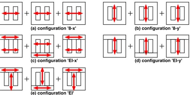
4.1 Ilustration of different configurations of three-layer core, with red arrow indicating the rolling direction (RD). . . 81
4.2 Geometry of electrical sheets of format A: (a) E-sheet; (b) I-sheet; (c) some detailes of format A . . . 83
4.3 Geometry of electrical sheets of format B: (a) E-sheet; (b) I-sheet; (c) 8-sheet; (d) some details of format B . . . 83
4.4 Transformer core structure : ’E-shaped’ sheet (yellow region) + ’I- shaped’ sheet (red region) with indication of RD (white arrows). RD of the ’E-shaped’ sheet is vertical and RD of the ’I-’E-shaped’ sheet is horizontal. (a) sectional view of the top yoke; (b) sectional view of the limb; (c) sectional view of the bottom yoke. . . 84
List of Figures vii
4.6 Illustration of anhysteretic measurement [Rekik, 2014]. . . 86
4.7 Macrograph picture of a standard industrial GO 3% silicon–iron lami-nation (Hi-B from Nippon Steel) (left); Pole figures of GO FeSi (right)
[Buvat, 2000] . . . 88
4.8 GO FeSi: Experimental measurement [Hubert et Daniel, 2008] -
anhys-teretic magnetization curves. . . 88
4.9 GO FeSi: Experimental measurement [Hubert et Daniel, 2008] -
anhys-teretic magnetostriction. . . 88
4.10 Texture of a NO FeSi lamination (left); Pole figures of NO FeSi (right) . . 89
4.11 NO FeSi: Experimental measurement - anhysteretic magnetization curves. 89
4.12 NO FeSi: Experimental measurement - anhysteretic magnetostriction. . . 89
4.13 Texture of FeNi Supra50 (left); Pole figures of FeNi Supra50 (right) [Cetin,
2014] . . . 91
4.14 FeNi Supra50: Experimental measurement [Cetin, 2014] - anhysteretic
magnetization curves. . . 91
4.15 FeNi Supra50: Experimental measurement [Cetin, 2014] - anhysteretic
magnetostriction. . . 91
4.16 Texture of FeCo Afk1 (left); Pole figures of FeCo Afk1 (right) [Savary
et al., 2018] . . . 92
4.17 FeCo Afk1: Experimental measurement [Savary et Hubert, 2017] -
an-hysteretic magnetization curves. . . 92
4.18 FeCo Afk1: Experimental measurement [Savary et Hubert, 2017] -
an-hysteretic magnetostriction. . . 92
4.19 GO FeSi: Comparison between SMSM results (dots) and experimental measurement (lines) [Hubert et Daniel, 2008] - anhysteretic
magnetiza-tion curves. . . 95
4.20 GO FeSi: Comparison between SMSM results (dots) and experimental measurement (lines) [Hubert et Daniel, 2008] - anhysteretic
magnetostric-tion curves. . . 95
4.21 Non-oriented FeSi: Comparison between SMSM results (dots) and
exper-imental measurement (lines) - anhysteretic magnetization curves. . . 97
4.22 Non-oriented FeSi: Comparison between SMSM results (dots) and
exper-imental measurement (lines) - anhysteretic magnetostriction curves. . . . 97
4.23 FeNi Supra50: Comparison of SMSM results (dots) to experimental
mea-surement (lines) - anhysteretic magnetization curve. . . 99
4.24 FeNi Supra50: Comparison of SMSM results (dots) to experimental
mea-surement (lines) - anhysteretic magnetostriction. . . 99
4.25 Magnetostrictive curve of FeCoAAFK1 and FeCoBAFK1 (a)
experimen-tal data (b) numerical results [Savary et al., 2018]. FeCoAAFK1 and
FeCoBAFK1 have been annealed at different temperatures allowing to
enhance or remove the bi-domains structure. FeCoBAFK1 corresponds to
4.26 FeCo Afk1: Comparison of SMSM results (dots) to experimental
mea-surement (lines) - anhysteretic magnetization curve. . . 101
4.27 FeCo Afk1: Comparison of SMSM results (dots) to experimental
mea-surement (lines) - anhysteretic magnetostriction. . . 101
4.28 Simulated magnetic (a) and magnetostrictive (b) behaviors under stress of
GO FeSi along RD. . . 103
4.29 Simulated magnetic (a) and magnetostrictive (b) behaviors under stress of
NO FeSi along RD. . . 103
4.30 Simulated magnetic (a) and magnetostrictive (b) behaviors under stress of
FeNi Supra50 along 45 from RD. . . 104
4.31 Simulated magnetic (a) and magnetostrictive (b) behaviors under stress of
FeCo Afk1 along RD. . . 104
4.32 Selected points for local strain measurements. . . 105
4.33 NO FeSi three-layer core: comparison measurement/simulation of the
lo-cal magnetostriction during anhysteretic procedure. . . 106
4.34 FeNi Supra50 three-layer core: comparison measurement/simulation of
the local magnetostriction during anhysteretic procedure. . . 107
4.35 FeCo Afk1 three-layer core: comparison measurement/simulation of the
local magnetostriction during anhysteretic procedure. . . 108
5.1 Experimental set up for prototype testing. . . 112
5.2 Selected points for acceleration measurements. . . 113
5.3 Comparison between modeled and measured displacements at some
se-lected points . . . 115
5.4 (a) Amplitude of the excitation current as function of magnetic induction in the central limb; (b) THD of the excitation current as function of
mag-netic induction amplitude in the central limb. . . 117
5.5 Measured and simulated amplitude of the relative displacement between several pairs of points on three-layer EI cores: (a)P1-P2; (b)P3-P4;
(c)P3-P5; (d)P4-P6. . . 119
5.6 (a) Measured noise level; (b) Simulated acoustic power . . . 120
5.7 Frequency spectrum of noise level on three-layer EI core with different materials: (a)FeCo Afk1; (b)NO FeSi; (c)FeNi Supra50; (d) background
noise . . . 121
5.8 Frequency spectrum of the relative displacement and velocity between two measuring points on FeCo Afk1 three-layer EI core: (a)displacement
P1-P2; (b)velocity P1-P2; (c)displacement P3-P5; (d)velocity P3-P5. . . . 121
5.9 Noise level of the NO FeSi three-layer core with different configurations. 123
5.10 Amplitude of relative displacement measured on different configurations
of NO FeSi three-layer cores. . . 123
5.11 Current in the three phases of one period of time. . . 125
5.12 Displacement field described by color density at t1 (left) and t2 (right).
List of Figures ix
5.13 Induced stress in-plane components for layer family 1 at instant t2 . . . . 126
5.14 Induced stress in-plane components for layer family 2 at instant t2 . . . . 126
5.15 Examples of modified geometries . . . 128
5.16 Current of three phases with maximum induction of 1.2T (top), 1.3T (middle) and 1.4T (bottom) on different geometries.. . . 129
5.17 Average RMS of current of three phases with different maximum induc-tions and geometries. . . 130
5.18 THD with different maximum inductions and geometries. . . 130
5.19 Acoustic power with different maximum flux density and geometries. . . 130
A.1 In-plane vibration mode for 8-shaped sheet (Format-A). . . 138
A.2 In-plane vibration mode for E-shaped sheet (Format-A). . . 138
A.3 In-plane vibration mode for I-shaped sheet (Format-A). . . 138
A.4 In-plane vibration mode for 8-shaped sheet (Format-B). . . 139
A.5 In-plane vibration mode for E-shaped sheet (Format-B). . . 139
A.6 In-plane vibration mode for I-shaped sheet (Format-B). . . 139
B.1 Distribution of the magnetic induction (left) and nodal equivalent force (right) for three-layer GO FeSi EI-core . . . 143
B.2 Distribution of the induced stress in-plane components for three-layer GO FeSi EI-core . . . 143
B.3 Distribution of the local displacement for three-layer GO FeSi EI-core, with a shape scale factor of 20000 . . . 143
B.4 Distribution of the magnetic induction (left) and nodal equivalent force (right) for NO FeSi 8-shaped core . . . 144
B.5 Distribution of the induced stress in-plane components for NO FeSi 8-shaped core . . . 144
B.6 Distribution of the local displacement for NO FeSi 8-shaped core, with a shape scale factor of 20000 . . . 144
B.7 Distribution of the magnetic induction (left) and nodal equivalent force (right) for FeNi Supra50 8-shaped core . . . 145
B.8 Distribution of the induced stress in-plane components for FeNi Supra50 8-shaped core . . . 145
B.9 Distribution of the local displacement for FeNi Supra50 8-shaped core, with a shape scale factor of 200000. . . 145
B.10 Distribution of the magnetic induction (left) and nodal equivalent force (right) for FeCo Afk1 8-shaped core . . . 146
B.11 Distribution of the induced stress in-plane components for FeCo Afk1 8-shaped core . . . 146
B.12 Distribution of the local displacement for FeCo Afk1 8-shaped core, with a shape scale factor of 2000. . . 146
C.1 Strategy of source tensor projection . . . 150
C.3 Magnetic force density (top); Magnetostriction induced force density (bot-tom) . . . 152
C.4 Displacements due to magnetostriction in direction X (left) and Y (right). 153
C.5 Displacements due to magnetic force in direction X (left) and Y (right). . 153
C.6 Displacements in direction X as a function of time at P2 (left);
Displace-ments in direction Y as a function of time at P1 (right) . . . 154
C.7 Displacements in direction X (left) and Y (right) as a function of time at P3154
D.1 Excitation current in primary coils . . . 156
List of Tables
2.1 Physical constants used for anhysteretic MSM [Daniel et al., 2014, Rekik,2014]. . . 48
2.2 Numerical parameters used for the irreversible field calculation. . . 49
4.1 List of material used in the experimental part and main characteristics . . 80
4.2 List of configuration-material three-layer cores . . . 82
4.3 Physical constants used for SMSM. . . 102
5.1 Resonance mode of structure ’E’, ’I’, ’E+I’ . . . 116
5.2 Numerical parameters and elastic constants used for transformer 2D
mod-eling. . . 124
Introduction
The world of transport, particularly in the aerospace industry, is undergoing deep changes. On one hand, the number of electrical comfort equipment, electronic control systems and navigation systems increases significantly. On the other hand, with the desire to reduce CO2 gas emission, "all electric aircrafts" (so-called carbon-free aircrafts) are developed. The electrical power supplied by the generators plugged to the turbojet has to be increased to feed these systems. Depending on the application, this electrical revolution is spreading to all parts of the energy transmission system, going from the power supply to the actu-ator through the electrical power chain. The electrical power is commonly transformed through power electronic devices and power transformers to adapt voltage, current and frequency to the final on board user. Therefore the increase of the electrical power leads to an increase of the size and mass of these devices at constant power to mass ratio (Fig.1).
The Auto Transformer Unit (ATU) Vac and
Figure 1: Thales Auto Transformer Unit (source figure from the internet [Thales,]) In order to make the switch to a viable solution, many scientific studies focus on optimizing the geometry of the electrical devices, but this single approach seems today not enough innovative to increase the power to mass ratio. The best way to solve this problem is to work on an evolution of both the core structrues and magnetic materials. Ferromagnetic materials have evolved little for several decades. However, research in
metallurgical industries has continued all over the world (and particularly in France at APERAM). Some products currently under development in the laboratories are close to being industrialized and adapted to the various functions mentioned above.
The newly developed ferromagnetic materials presenting a higher power density are often made of iron and cobalt. Power transformers made with these materials generate unfortunately a loud noise in operation. This noise is usually separated into load noise
[Ertl et Landes, 2007] [Wang et al., 2011] and no-load noise. The former is due to
mag-netic interactions (especially Lorentz forces) between the current carrying windings and transformer magnetic stray field. The latter is caused by periodic deformations of sheets linked with the structure of the transformer core [Chang et al., 2011] [Hsu et al., 2012]. This sheet deformation is believed resulting from many phenomena. Up to now, several factors have been claimed to have relevant effects on flux distribution and core vibrations, such as bolt holes [Balehosur et al., 2010], core clamping [Penin et al., 2014b] and core structures [Chang et al., 2011].
Sheet deformation has two origins: i) elastic strain associated with magneto-static forces appearing on the free surfaces and in the volume; ii) magnetostriction depend-ing on the local magnetic state of the material [Du Trémolet de Lacheisserie, 1993a]. Magnetic forces are induced when the medium exhibits inhomogeneous permeability. Magnetostrictive strain is associated with the re-organization of magnetic domains. The domains are characterized by a magnetization vector whose magnitude equals the satu-ration magnetization of the material, and free magnetostriction strain depending on the magnetostriction constants and magnetization direction. When a magnetic field ~H is ap-plied, the domain wall moves and then magnetization vectors rotate toward the direction of the applied field at high magnetic field leading to a displacement of domain walls that separate the magnetic domains, increasing the volume fraction of domains aligned with the field. Thus a deformation appears at the macroscopic scale induced by the free strain ✏µ of the considered domains. The crystallographic texture has a strong impact on the magnetostrictive behavior [Hubert et Daniel, 2008]. It leads to both magnetic and magne-tostrictive anisotropies (coupled magneto-mechanical phenomena with isotropic magnetic and magnetostrictive behavior are studied in [Fonteyn et al., 2010] [Belahcen, 2005]).
Modeling and optimization of the power transformer, in order to reduce the noise emission, involves a multi-physical approach including electromagnetic, mechanical and acoustic aspects. It is so complex that, despite strong recent efforts in this field, there is currently no robust and reliable commercial software nor academic code yet available to estimate and optimize the global deformation and the noise level in laminated trans-former cores, with the consideration of material anisotropy, nonlinearity of the magneto-mechanical behavior and stress dependency. Such a tool is however essential for opti-mization. The goal of this thesis work is to propose a complete numerical modeling of this noise generation to allow an optimization of the transformer with respect to the mass, noise, inrush, efficiency, thermal, cost constraints thanks to the simulation and optimiza-tion of material and design of the devices. It should also be noted that in the context of noise generation, the magnetic circuit can not be considered independently to its
envi-Introduction 3 ronment. It will thus be important to be able to evaluate the magnitudes of the induced forces injected into the structure at the fixing points of the transformer. This aspect of the simulation could ultimately make it possible to optimize the fixations (number, arrange-ment) by minimizing the transmitted vibrations, and/or by reducing the stresses in the material which can lead to a reduction in the magnetic permeability of the material or to an undesirable modification of its magnetostrictive behavior and the global performance.
This dissertation is divided into four chapters. Chapter 1 introduces the basic con-cepts of the noise generation in power transformers, existing studies in this area and presents the strategy to solve the problems. Chapter 2 is dedicated to the modeling of magneto-mechanical behavior, including a full multi-scale model with and without hys-teresis extension, a simplified multi-scale model adapted to the finite element modeling chain. Chapter3addresses the fully coupled modeling chain of power transformer core vibration and noise emission, using finite element method. Chapter 4and 5present the measurements on power transformer prototype and its comparison with simulation. A nu-merical optimization procedure of geometry is finally proposed, allowing better acoustic and electromagnetic performances to be reached.
Chapter 1
Introduction to Transformer Noise
Contents
1.1 Introduction to power transformer. . . 6
1.1.1 Working principle . . . 6
1.1.2 Transformer core . . . 7
1.1.3 Electrical steel sheet . . . 8
1.2 Noise source . . . 9
1.2.1 Core noise . . . 9
1.2.2 Winding noise . . . 11
1.2.3 Cooling system noise . . . 11
1.3 State of the art . . . 12
1.3.1 Factors related to core noise . . . 12
1.3.2 Research approaches . . . 14
1.3.3 Research scale . . . 18
1.4 Objective and strategy. . . 22
1.4.1 Material model . . . 23
1.4.2 Homogenization procedure . . . 23
1.4.3 Finite element modeling chain . . . 24
1.4.4 Validation model/measurement. . . 24
1.1 Introduction to power transformer
1.1.1 Working principle
A power transformer is an electrical device that transfers electrical energy between two or more circuits through electromagnetic induction. It is used to increase or decrease the alternating voltages in the electrical system. The power transformer is typically com-posed of a ferromagnetic core, several current carrying windings, holding structures and accessories such as the cooling system, illustrated in Fig.1.1.
Figure 1.1: Illustration of the power transformer parts (source figure from the website [Siemens,]).
The basic theory of the power transformer is simple. The primary windings that carry varying current creates a varying magnetic flux in the transformer core. The transformer core made of ferromagnetic material guides and keeps the magnetic flux inside the core. Secondary windings get back the corresponding voltage and current by means of elec-tromagnetic flux density. The proportion of the input and output voltage can be easily adjusted by the number of winding turns.
The power transformer comes with various types, from the largest ones used for power grid with thousands of tons to the smallest ones integrated into electronic cards. The clas-sification of power transformers can be carried out from different angles. It could be monophase or polyphase for different electric systems. In terms of cooling type, large transformers used in power distribution are often cooled by oil for better efficiency, while medium and small transformers are normally cooled by air for simplicity. Power trans-formers that amplify the voltage are called step-up transtrans-formers, otherwise, they are called
Introduction to power transformer 7 step-down transformers. The autotransformer has one winding that is tapped at some point along the winding (without Galvanic insulation), making it possible to modify the ratio between the input and output voltage.
1.1.2 Transformer core
The transformer core is usually made of very soft ferromagnetic materials for high ef-ficiency. It comes with different types, such as bulk cores and laminated steel cores. Bulk cores are often made of ferrite, a ferromagnetic ceramic material. It is usually used for high-frequency applications, because of its non-conductivity. This prevents the eddy currents and leads to a low no-load loss for the power transformer. However, the magne-tization saturation of the ferrite is about 0.3T , which is low compared to the iron based ferromagnetic laminations. Meanwhile, in the industry of power transmission, the most widely used is the laminated steel core, which is the studying object of this thesis.
The laminated steel core is made of an assembly of hundreds of thin sheets to ensure a homogeneous magnetic field through the thickness and more importantly to limit the eddy currents. Eddy currents losses in a magnetic core can be greatly reduced by reducing the thickness of the electrical sheet. Instead of having one big solid piece of magnetic material, it is splited into hundreds of thin sheets of 0.2 0.5mm thickness (Fig.1.2). These sheets are insulated from each other by specific coatings or papers, to increase the surface resistance and prevent the flow of eddy currents between electrical sheets.
Figure 1.2: Eddy currents within a solid iron transformer core (left) and a laminated transformer core composed of insulated sheets (right).
Associated to the forming process (hot/cold rolling, heat treatments), transformer sheets usually exhibit anisotropic magnetic and mechanical behaviors. Classical on-board electrical transformers are for example made of Non-Oriented FeSi or FeCo alloys. These sheets exhibit the highest induction (and permeability) at a given magnetic field level along the rolling direction (RD). The transformer core is consequently designed to in-crease the volume of material offering improved permeability in the direction of magnetic field.
One common design of laminated core is made from interleaved stacks of ’E-shaped’ steel sheets capped with ’I-shaped’ pieces, named ’E-I’ core. This solution can reduce
the manufacturing cost and facilitate the winding fabrication. ’E-shaped’ and ’I-shaped’ sheets are cut along the rolling direction of the lamination as shown in Fig.1.3. They are positioned alternatively on top or on bottom of the transformer in order to dilute parasitic air-gaps and limit their effects [Weiser et Pfützner, 1998].
RD
RD
Figure 1.3: Example of an E-I stacked core (RD indicates the rolling direction)
1.1.3 Electrical steel sheet
The electrical steel sheet is an essential component for the fabrication of power trans-formers and electrical motors. The electrical steel sheet is usually manufactured by a process called rolling, in which metal block is passed through a pair of rolls to reduce the thickness. This process is repeated several times to obtain an electrical steel sheet with a thickness of 0.2 2mm. Fig.1.4 gives an illustration of the rolling process, with an in-dication of rolling direction (RD), transverse direction (TD), and normal direction (ND). These sheets are then cut to their final shape by punching, laser, or water jet cutting.
RD TD
ND
Figure 1.4: Rolling process schematic view with indication of rolling direction (RD), transverse direction (TD), and normal direction (ND).
Noise source 9 Electrical steel is usually tailored to produce specific magnetic properties: low hys-teresis loss, small magnetostriction, and high magnetic permeability. Looking for a low magnetostriction is a more recent issue. Electrical steels usually indicate iron based ma-terials that contain a small amount of silicon (up to 6.5%). They are often called FeSi alloy for simplicity reasons. A special process allows crystal size and orientation to be controlled allowing to orient all magnetic domains along RD (grain-oriented (GO) FeSi). This strong anisotropy favors the magnetic and magnetostrictive performances along RD making this material widely used in the large distribution power transformers, where the direction of magnetic flux is constant in most of the parts. Most of the FeSi sheets are processed to develop an isotropic (compared to GO FeSi) behavior. These materials, called Non-Oriented (NO) FeSi, are often used inside rotating machines where the di-rection of the magnetic flux at a given point changes all the time. For the application of low-noise power transformer, other high-end materials are also good candidates, such as FeNi Supra50 and FeCo Afk1. FeNi Supra50 is composed of 50% Iron and 50% Nickel, forming a quasi-single-crystal cubic texture. This creates two easy axes along RD and TD and leads to a low magnetostriction in these directions. FeCo Afk1 develops a low magnetostriction under special (confidential) heat treatment, which is still under devel-opment, in order to obtain the optimized performance. These materials will be presented more extensively in the next chapters.
1.2 Noise source
The noise of the power transformer, or transformer ’humming’, has been known as a big issue for several decades. A common solution, perhaps the easiest one, to reduce noise emission is to stop it from the transmission. For example, a solution is to place sound barriers or to use a full enclosure [Yang et Zhang, 2006]. However, any additional mass is strictly limited for aeronautic power transformers, making it necessary to reduce the noise source itself. The noise source can be sorted into three main categories: core noise, load noise and noise from cooling systems (Fig.1.5).
1.2.1 Core noise
Noise from the transformer core is considered as the dominant source of the noise. It is caused by the periodic deformation/movement of the electric sheets, under the alternative magnetic field [Chang et al., 2011,Hsu et al., 2012]. This deformation is produced by the combination effects of magnetostriction and magnetic forces (or Maxwell forces). Magnetostriction
Magnetostriction is an intrinsic property for all ferromagnetic materials. When a piece of magnetic material is magnetized, it undergoes a small deformation, called magnetostric-tion. It has been first discovered in 1842 by Joule, that the ferromagnetic magnetic
mate-Figure 1.5: Sources of power transformer noise.
rial changes the shape under magnetic field [Williams et Shockley, 1949]. The mechanism of the magnetostriction can be explained by magnetic domain theory. Under external magnetic field, the magnetic domains tend to rotate and reorient to the direction of the magnetic field, in order to minimize the local energy, thus creates deformation. Since the deformation is isochoric, there is an opposite dimensional change in the orthogonal direction.
For applications such as power transformers, magnetostriction creates undesirable vi-brations. For electrical sheets used in electrical motors and power transformers, often made of FeSi, the magnetostrictive strain is normally lower than 10ppm. However, some alloys come with huge magnetostriction under relatively small magnetic fields. One of the most famous ’giant’ magnetostriction material is Terfenol-D, which reaches about 2000ppm at room temperature. Applications based on these ’giant’ magnetostriction ma-terials are sensors and actuators [Anjanappa et Bi, 1917].
Magnetostriction depends on the applied field, mechanical stress, material type, and even temperature. It is important to notice that the magnetostriction is independent of the sign of the magnetic field. This results in a double frequency of magnetostriction compared to its magnetic excitation. Because of its non-linearity, higher harmonics also appear, which may trigger mechanical resonances of the whole transformer structure. Magnetic forces
Magnetic forces appear when magnetic field goes from one medium to another. In the core power transformer, magnetic forces are generally concentrated at the joints [Liu et al., 2016], where magnetic field meets the air-gap. This makes the noise emission of the power transformer highly depended on the fabrication process, such as the flatness of
Noise source 11 the electric sheets, electric sheets cutting method and assembling precision. Admittedly, the core vibration induced by magnetic forces can not be easily reduced, because the transformer core is always assembled by hundreds of electric sheet and there are always parasite air-gaps.
1.2.2 Winding noise
Winding noise, also called load noise or coil noise, is due to the Lorentz forces resulting from the interaction of magnetic leakage fields and the load currents [Ertl et Landes, 2007,
Wang et al., 2011]. Forces acting on the windings can cause vibration. The frequency of
the winding vibration is twice the current frequency [Rausch et al., 2002, Shao et al., 2012]. If it falls within the resonance frequency of the windings, large audible noise will be generated. In general, winding noise makes a limited contribution to the total transformer noise. The difference between no load and full load noise is usually no greater than 1 or 2dB, if the coil is well secured to the circuit board or is well damped. An example of the vibration of the windings on power transformer is given in Fig.1.6.
Figure 6. Qualitative displacement of free-vibration modes of the investigated winding structure at elastic bearing boundary conditions Flexure mode
mixed vibration mode (radial and axial) Axial oscillation 1st eigenfrequency at 28Hz 2nd eigenfrequency at 46Hz 18th eigenfrequency at 119Hz
Investigation of
load noise
generation
795
Downloaded by ECOLE NORMALE SUPERIEURE DE CACHAN At 03:26 27 October 2014 (PT)
(a) 28 Hz
Figure 6. Qualitative displacement of free-vibration modes of the investigated winding structure at elastic bearing boundary conditions
Flexure mode
mixed vibration mode (radial and axial) Axial oscillation 1st eigenfrequency at 28Hz 2nd eigenfrequency at 46Hz 18th eigenfrequency at 119Hz
Investigation of
load noise
generation
795
Downloaded by ECOLE NORMALE SUPERIEURE DE CACHAN At 03:26 27 October 2014 (PT)
(b) 46 Hz
Figure 6. Qualitative displacement of free-vibration modes of the investigated winding structure at elastic bearing boundary conditions
Flexure mode
mixed vibration mode (radial and axial) Axial oscillation 1st eigenfrequency at 28Hz 2nd eigenfrequency at 46Hz 18th eigenfrequency at 119Hz
Investigation of
load noise
generation
795
Downloaded by ECOLE NORMALE SUPERIEURE DE CACHAN At 03:26 27 October 2014 (PT)
(c) 119 Hz
Figure 1.6: Example of the winding vibration in power transformers [Ertl et Landes, 2007].
In order to reduce the winding noise, good damping is often the key point. However, the progressive degradation of damping material (damage, oxidation...) may lead to more noise generation. Studies are also carried out to develop low noise windings, with a resonance frequency far from the current frequency.
1.2.3 Cooling system noise
Power transformers produce a huge amount of energy losses, such as iron losses in elec-trical sheets and joule losses in the windings. These losses act as heat sources, that have
to be removed by the cooling system. Fans and pump are widely used for creating air flow and oil flow to cool the power transformer. As part of the power transformer, the cooling system usually adds a non-negligible contribution to the noise emission. This aspect is rarely studied in the literature. In this thesis, only the core noise is considered.
1.3 State of the art
1.3.1 Factors related to core noise
The noise generated by power transformers and inductors [Krell et al., 2000, Valkovic,
1998,Rossi et Le Besnerais, 2015] has been studied for several decades and the related
lit-erature is abundant. Up to now, several factors have been claimed to have relevance to the flux distribution and core vibrations, such as material core nature, core joints, clamping stress, and electrical excitation.
• Core shape: Power transformers made of the same material can have totally dif-ferent performance, depending on the core shapes [Chang et al., 2011]. Not only does the core shape influence the noise emission, but also has an impact on the winding section, copper fill factor, efficiency, power density, and thermal perfor-mances. Shuai et al. [Shuai et Biela, 2015] compares the performances of four power transformer cores with different shapes, including rectangular, square, oval and ring shape, illustrated in Fig.1.7. Both numerical simulations and experimental measurements are carried out in this work. Compared to the conventional rectan-gular core, the oval core leads to lower vibration and noise emission and further reduction can be achieved by using a ring core. However, the ring core leads to a much lower power density than the other core shapes. There is always a trade-off between different performances of the power transformer, when it comes to a certain application.
Table IV: Comparison of optimal design at maximum power density by using different cores.
Parameter
Core
Rectangular
Square
Oval
Ring
Core cross section area [mm
2]
3403.2
5029.2
2177.6
997.2
Window area [mm
2]
1703.2
1184.5
2663.9
3728.1
Magnetic length [mm]
208.2
175.4
238
291.8
Core volume [dm
3]
0.708
0.882
0.518
0.291
Boxed volume [dm
3]
1.83
1.9
2.25
2.35
Number of turns
28:9
19:6
44:14
97:32
Copper fill factor
26.13%
25.42%
28.28%
30.91%
Core loss [W]
32.32
39.98
23.35
12.83
Winding loss [W]
67.95
76.57
69.01
107.64
Efficiency
99.6%
99.54%
99.63%
99.52%
B
max[T]
0.96
0.957
0.955
0.945
E
max[kV/mm]
7.83
7.94
7.99
7.93
Maximum temperature [ C]
119
119
118
118.6
Power density [kW/L]
13.66
13.16
11.11
10.87
2D View (for rectangular, square
and oval core, only one core
is shown)
much more losses are generated in the winding. Therefore, both the power density and the efficiency of the ring
core based transformers are limited due to the heat dissipation capability.
5 Conclusions
Medium frequency transformers are small in size and weight compared with conventional line frequency
trans-formers. The major challenges associated with MFTs are cooling and isolation as well as the acoustic noise
emission. In this paper, the influence of core shapes on the vibration and acoustic noise emission of magnetic cores
are investigated based on FEM simulation and measurements. The modeling methods of the core vibration are
investigated and a 2D model to calculate the deformation of the core under electrical excitation is implemented
and used to simulate the deformation of several cores with different geometric shapes in static case. The vibration
and acoustic measurements are performed on nanocrystalline material VITROPERM 500F based uncut cores with
rectangular, oval and ring shapes. The measured maximum deformation at the base frequency of magnetostriction
shows good agreement with the results of static simulation. Both vibration and acoustic measurements confirm
that the nanocrystalline material is superior for low noise transformer design. Moreover, this material is also
ad-vantageous in terms of power density and efficiency compare to other core materials, which makes nanocrystalline
alloy the most suitable one for highly efficient, compact and quiet MFT design. Compared to the conventional
rectangular core, oval core has lower vibration and noise emission and further reduction can be achieved by using
a ring core in which case the measured SPL is below 40 dBA by avoiding the excitation near resonant frequency.
For the same specifications, MFTs based on rectangular core can achieve higher power density compared to square
and oval core based transformers. Due to the limitation of heat dissipation, the achievable power density of
trans-formers based on ring core is even lower compared to the aforementioned core shapes. Nevertheless, the pareto
fronts of optimal designs of MFTs based on different core shapes show that the difference is not significant.
There-fore, in case that low acoustic noise emission needs to be considered, nanocrystalline material based uncut core
with oval shape is a good choice for MFT design without sacrificing much power density compared to rectangular
core.
Acknowledgment
The authors would like to thank ECPE, the European Power Electronics Research Network, for financial support of
the research project and VACUUMSCHMELZE GmbH for providing the core samples and valuable information
about the core materials.
(a) Rectangular core
Table IV: Comparison of optimal design at maximum power density by using different cores.
Parameter
Core
Rectangular
Square
Oval
Ring
Core cross section area [mm
2]
3403.2
5029.2
2177.6
997.2
Window area [mm
2]
1703.2
1184.5
2663.9
3728.1
Magnetic length [mm]
208.2
175.4
238
291.8
Core volume [dm
3]
0.708
0.882
0.518
0.291
Boxed volume [dm
3]
1.83
1.9
2.25
2.35
Number of turns
28:9
19:6
44:14
97:32
Copper fill factor
26.13%
25.42%
28.28%
30.91%
Core loss [W]
32.32
39.98
23.35
12.83
Winding loss [W]
67.95
76.57
69.01
107.64
Efficiency
99.6%
99.54%
99.63%
99.52%
B
max[T]
0.96
0.957
0.955
0.945
E
max[kV/mm]
7.83
7.94
7.99
7.93
Maximum temperature [ C]
119
119
118
118.6
Power density [kW/L]
13.66
13.16
11.11
10.87
2D View (for rectangular, square
and oval core, only one core
is shown)
much more losses are generated in the winding. Therefore, both the power density and the efficiency of the ring
core based transformers are limited due to the heat dissipation capability.
5 Conclusions
Medium frequency transformers are small in size and weight compared with conventional line frequency
trans-formers. The major challenges associated with MFTs are cooling and isolation as well as the acoustic noise
emission. In this paper, the influence of core shapes on the vibration and acoustic noise emission of magnetic cores
are investigated based on FEM simulation and measurements. The modeling methods of the core vibration are
investigated and a 2D model to calculate the deformation of the core under electrical excitation is implemented
and used to simulate the deformation of several cores with different geometric shapes in static case. The vibration
and acoustic measurements are performed on nanocrystalline material VITROPERM 500F based uncut cores with
rectangular, oval and ring shapes. The measured maximum deformation at the base frequency of magnetostriction
shows good agreement with the results of static simulation. Both vibration and acoustic measurements confirm
that the nanocrystalline material is superior for low noise transformer design. Moreover, this material is also
ad-vantageous in terms of power density and efficiency compare to other core materials, which makes nanocrystalline
alloy the most suitable one for highly efficient, compact and quiet MFT design. Compared to the conventional
rectangular core, oval core has lower vibration and noise emission and further reduction can be achieved by using
a ring core in which case the measured SPL is below 40 dBA by avoiding the excitation near resonant frequency.
For the same specifications, MFTs based on rectangular core can achieve higher power density compared to square
and oval core based transformers. Due to the limitation of heat dissipation, the achievable power density of
trans-formers based on ring core is even lower compared to the aforementioned core shapes. Nevertheless, the pareto
fronts of optimal designs of MFTs based on different core shapes show that the difference is not significant.
There-fore, in case that low acoustic noise emission needs to be considered, nanocrystalline material based uncut core
with oval shape is a good choice for MFT design without sacrificing much power density compared to rectangular
core.
Acknowledgment
The authors would like to thank ECPE, the European Power Electronics Research Network, for financial support of
the research project and VACUUMSCHMELZE GmbH for providing the core samples and valuable information
about the core materials.
(b) Square core
Table IV: Comparison of optimal design at maximum power density by using different cores.
Parameter
Core
Rectangular
Square
Oval
Ring
Core cross section area [mm
2]
3403.2
5029.2
2177.6
997.2
Window area [mm
2]
1703.2
1184.5
2663.9
3728.1
Magnetic length [mm]
208.2
175.4
238
291.8
Core volume [dm
3]
0.708
0.882
0.518
0.291
Boxed volume [dm
3]
1.83
1.9
2.25
2.35
Number of turns
28:9
19:6
44:14
97:32
Copper fill factor
26.13%
25.42%
28.28%
30.91%
Core loss [W]
32.32
39.98
23.35
12.83
Winding loss [W]
67.95
76.57
69.01
107.64
Efficiency
99.6%
99.54%
99.63%
99.52%
B
max[T]
0.96
0.957
0.955
0.945
E
max[kV/mm]
7.83
7.94
7.99
7.93
Maximum temperature [ C]
119
119
118
118.6
Power density [kW/L]
13.66
13.16
11.11
10.87
2D View (for rectangular, square
and oval core, only one core
is shown)
much more losses are generated in the winding. Therefore, both the power density and the efficiency of the ring
core based transformers are limited due to the heat dissipation capability.
5 Conclusions
Medium frequency transformers are small in size and weight compared with conventional line frequency
trans-formers. The major challenges associated with MFTs are cooling and isolation as well as the acoustic noise
emission. In this paper, the influence of core shapes on the vibration and acoustic noise emission of magnetic cores
are investigated based on FEM simulation and measurements. The modeling methods of the core vibration are
investigated and a 2D model to calculate the deformation of the core under electrical excitation is implemented
and used to simulate the deformation of several cores with different geometric shapes in static case. The vibration
and acoustic measurements are performed on nanocrystalline material VITROPERM 500F based uncut cores with
rectangular, oval and ring shapes. The measured maximum deformation at the base frequency of magnetostriction
shows good agreement with the results of static simulation. Both vibration and acoustic measurements confirm
that the nanocrystalline material is superior for low noise transformer design. Moreover, this material is also
ad-vantageous in terms of power density and efficiency compare to other core materials, which makes nanocrystalline
alloy the most suitable one for highly efficient, compact and quiet MFT design. Compared to the conventional
rectangular core, oval core has lower vibration and noise emission and further reduction can be achieved by using
a ring core in which case the measured SPL is below 40 dBA by avoiding the excitation near resonant frequency.
For the same specifications, MFTs based on rectangular core can achieve higher power density compared to square
and oval core based transformers. Due to the limitation of heat dissipation, the achievable power density of
trans-formers based on ring core is even lower compared to the aforementioned core shapes. Nevertheless, the pareto
fronts of optimal designs of MFTs based on different core shapes show that the difference is not significant.
There-fore, in case that low acoustic noise emission needs to be considered, nanocrystalline material based uncut core
with oval shape is a good choice for MFT design without sacrificing much power density compared to rectangular
core.
Acknowledgment
The authors would like to thank ECPE, the European Power Electronics Research Network, for financial support of
the research project and VACUUMSCHMELZE GmbH for providing the core samples and valuable information
about the core materials.
(c) Oval core
Table IV: Comparison of optimal design at maximum power density by using different cores.
Parameter Core Rectangular Square Oval Ring
Core cross section area [mm2] 3403.2 5029.2 2177.6 997.2
Window area [mm2] 1703.2 1184.5 2663.9 3728.1
Magnetic length [mm] 208.2 175.4 238 291.8
Core volume [dm3] 0.708 0.882 0.518 0.291
Boxed volume [dm3] 1.83 1.9 2.25 2.35
Number of turns 28:9 19:6 44:14 97:32
Copper fill factor 26.13% 25.42% 28.28% 30.91%
Core loss [W] 32.32 39.98 23.35 12.83 Winding loss [W] 67.95 76.57 69.01 107.64 Efficiency 99.6% 99.54% 99.63% 99.52% Bmax[T] 0.96 0.957 0.955 0.945 Emax[kV/mm] 7.83 7.94 7.99 7.93 Maximum temperature [ C] 119 119 118 118.6 Power density [kW/L] 13.66 13.16 11.11 10.87
2D View (for rectangular, square and oval core, only one core
is shown)
much more losses are generated in the winding. Therefore, both the power density and the efficiency of the ring core based transformers are limited due to the heat dissipation capability.
5 Conclusions
Medium frequency transformers are small in size and weight compared with conventional line frequency trans-formers. The major challenges associated with MFTs are cooling and isolation as well as the acoustic noise emission. In this paper, the influence of core shapes on the vibration and acoustic noise emission of magnetic cores are investigated based on FEM simulation and measurements. The modeling methods of the core vibration are investigated and a 2D model to calculate the deformation of the core under electrical excitation is implemented and used to simulate the deformation of several cores with different geometric shapes in static case. The vibration and acoustic measurements are performed on nanocrystalline material VITROPERM 500F based uncut cores with rectangular, oval and ring shapes. The measured maximum deformation at the base frequency of magnetostriction shows good agreement with the results of static simulation. Both vibration and acoustic measurements confirm that the nanocrystalline material is superior for low noise transformer design. Moreover, this material is also ad-vantageous in terms of power density and efficiency compare to other core materials, which makes nanocrystalline alloy the most suitable one for highly efficient, compact and quiet MFT design. Compared to the conventional rectangular core, oval core has lower vibration and noise emission and further reduction can be achieved by using a ring core in which case the measured SPL is below 40 dBA by avoiding the excitation near resonant frequency. For the same specifications, MFTs based on rectangular core can achieve higher power density compared to square and oval core based transformers. Due to the limitation of heat dissipation, the achievable power density of trans-formers based on ring core is even lower compared to the aforementioned core shapes. Nevertheless, the pareto fronts of optimal designs of MFTs based on different core shapes show that the difference is not significant. There-fore, in case that low acoustic noise emission needs to be considered, nanocrystalline material based uncut core with oval shape is a good choice for MFT design without sacrificing much power density compared to rectangular core.
Acknowledgment
The authors would like to thank ECPE, the European Power Electronics Research Network, for financial support of the research project and VACUUMSCHMELZE GmbH for providing the core samples and valuable information about the core materials.
(d) Ring core
Figure 1.7: Studied core shapes in [Shuai et Biela, 2015].
• Core joints: Stacked cores are built up from a stack of electrical sheets, usually cut in form of ’E’, ’I’ or ’C’. To stack these laminations together, an overlap is often
State of the art 13 needed to reduce the core noise. The joint with only one step overlap is called single step lap (SSL). The joint with multi-step overlap is called multi step lap (MSL), shown in Fig.1.8. The MSL is widely used in distribution power transformer, in order to allow a better distribution of the magnetic flux at the joints, and thus reduce the core loss and the noise emission [Mechler et Girgis, 2000]. Zhu et al. [Zhu
et al., 2013] find that filling the multi-joint gaps with nanocrystalline soft magnetic
composite material decreases magnetostriction and vibrations of the core because of an improved distribution of magnetic flux. Hsu et al. [Hsu et al., 2014] propose a new method to reduce the transformer core noise by re-arranging the step-lapped joint structure. They also found that an increasing number of step laps increases the core losses and vibrations.
4
a)
b)
Fig.2-1: The mitred joint constructions [8]
a) Cross-step construction
b) Longitudinal step construction
a)
b)
c)
d)
Fig.2-2: Mitred joint corner
a) Single step lap
b) Side view of single step lap with two laminations per step
c) Multistep lap (four steps)
d) Side view of multi-step lap with two laminations per step
2.2 Study of transformer core noise
It is generally accepted that magnetostriction is a cause of transformer core vibration
and noise. Magnetostriction ( ) is a deformation of magnetic materials due to
magnetisation [9]. It is defined in Eq. 2.1 as follows
Figure 1.8: Single step lap joints (left); Multi step lap joints (right) [Phophongviwat, 2013].
• Clamping stress: The clamping of the power transformer core allows the sheets to be stacked together and provides an additional mechanical rigidity of the struc-ture. Stress reduces the air-gaps between the electrical sheets on the overlap region, and finally has an impact on the core losses and core noise. There are two types of clampings: One in the rolling direction or transverse direction of the electrical sheets, holding the yokes and limbs together. The other, called C-clamp, com-presses the sheets together from their upper and lower surface (normal direction). Mizokami et al. [Mizokami et Kurosaki, 2015] experimentally demonstrates that the compression clamping stress along rolling direction of the electrical steel in-creases magnetostriction and noise level. The schematic of the mechanism for ap-plying compression to a limb is shown in Fig.1.9. Meanwhile, Penin et al. [Penin
et al., 2014b] finds that the C-clamping helps to reduce core noise. The optimized
pressure is around 0.8MPa. A lack of C-clamping or a non-uniform one has a direct and unwanted influence on the core losses and vibrations. However, the clamping of the power transformer is complex and can be difficult to adjust in massive pro-duction.
• Current DC bias: Although power transformers are normally designed to operate under sinusoidal excitation, in some particular cases, a direct current (DC) compo-nent may be superimposed in primary or secondary windings. This is caused by

![Figure 2.1: Longitudinal anhysteretic magnetostrictions of three ferromagnetic materials - measurements carried out at LMT [Fall, 2017].](https://thumb-eu.123doks.com/thumbv2/123doknet/14617755.733306/44.892.279.617.650.923/figure-longitudinal-anhysteretic-magnetostrictions-ferromagnetic-materials-measurements-carried.webp)
![Figure 2.5: Ideal magnetization process: magnetization curve [Daniel, 2003] and mag- mag-netostriction curve.](https://thumb-eu.123doks.com/thumbv2/123doknet/14617755.733306/48.892.133.764.585.763/figure-ideal-magnetization-process-magnetization-curve-daniel-netostriction.webp)


![Figure 4.5: Block diagram and photo of the measuring set-up [Rekik, 2014].](https://thumb-eu.123doks.com/thumbv2/123doknet/14617755.733306/103.892.140.749.231.566/figure-block-diagram-photo-measuring-set-rekik.webp)
![Figure 4.7: Macrograph picture of a standard industrial GO 3% silicon–iron lamination (Hi-B from Nippon Steel) (left); Pole figures of GO FeSi (right) [Buvat, 2000]](https://thumb-eu.123doks.com/thumbv2/123doknet/14617755.733306/105.892.129.766.163.467/figure-macrograph-picture-standard-industrial-silicon-lamination-nippon.webp)

