HAL Id: hal-00951892
https://hal.archives-ouvertes.fr/hal-00951892
Submitted on 25 Feb 2014
HAL is a multi-disciplinary open access
archive for the deposit and dissemination of
sci-entific research documents, whether they are
pub-lished or not. The documents may come from
teaching and research institutions in France or
abroad, or from public or private research centers.
L’archive ouverte pluridisciplinaire HAL, est
destinée au dépôt et à la diffusion de documents
scientifiques de niveau recherche, publiés ou non,
émanant des établissements d’enseignement et de
recherche français ou étrangers, des laboratoires
publics ou privés.
DFM synthesis approach based on product-process
interface modelling. Application to the peen forming
process.
Jawhar El Gueder, Lionel Roucoules, Emmanuelle Rouhaud, Florent
Cochennec
To cite this version:
Jawhar El Gueder, Lionel Roucoules, Emmanuelle Rouhaud, Florent Cochennec. DFM synthesis
approach based on product-process interface modelling. Application to the peen forming process..
20th CIRP Design Conference - Global Product Development, Apr 2010, Nantes, France. pp.265-277,
�10.1007/978-3-642-15973-2_26�. �hal-00951892�
Science Arts & Métiers (SAM)
is an open access repository that collects the work of Arts et Métiers ParisTech
researchers and makes it freely available over the web where possible.
This is an author-deposited version published in:
http://sam.ensam.eu
Handle ID: .
http://hdl.handle.net/10985/7801
To cite this version :
Jawhar ELGUEDER, Lionel ROUCOULES, Emmanuelle ROUHAUD, Florent COCHENNEC
-DFM synthesis approach based on product-process interface modelling. Application to the peen
forming process. - 2011
Any correspondence concerning this service should be sent to the repository
DFM synthesis approach based on product-process interface modelling. Application to
the peen forming process.
J. Elgueder1, L. Roucoules2, E. Rouhaud1, F. Cochennec1
1
University of Technology of Troyes, Laboratory of Mechanical Systems and Concurrent Engineering,
Charles Delaunay Institute – FRE 2848, 12 rue Marie Curie BP2060 10010 TROYES Cedex France.
E-mail: [email protected], [email protected]
2
Arts et Métiers ParisTech ; CNRS, LSIS, 2 cours des Arts et Métiers 13617 Aix en Provence, France. E-mail: [email protected]
Abstract
Engineering design approach are curently CAD-centred design process. Manufacturing information is selected and assessed very late in the design process and above all as a reactive task instead of being proactive to lead the design choices. DFM appraoches are therefore assesment methods that compare several design alternatives and not real design approaches at all.
Main added value of this research work concerns the use of a product-process interface model to jointly manage both the product and the manufacturing data in a proactive DFM way. The DFM synthesis approach and the interface model are presented via the description of the DFM software platform.
Key words:
product-process interface / DFM / virtual prototyping / manufacturing process selection / manufacturing data management, peen forming.
1. INTRODUCTION
For almost 30 years CAD systems have been developed and improved to currently provide very powerful features to support product’s forms modelling. PLM approaches and systems have also been highly developed for the last decade to manage the entire product lifecycle information. Nevertheless CAD and PLM systems are currently used the central systems that make the design process a geometric-centred process. CAD model is indeed very often proposed by one person and is used as an input for product analyses (CAM, FEA...). The design experts therefore react and ask for changes that are propagated according to several relations either in the CAD or the PLM model. The design process is then a “redo until right” process.
The paper aims at presenting a design approach
based on a DFM synthesis by least commitment1
process. This approach provides a more proactive
position of each design expert (particularly
manufacturing) involved in the design process in order to set the CAD model as the result of a collaborative decision making process. The design is then based on a “right the first time” process. This approach is based
1 “Least commitment” has to be understood as “including as less
design constraints as possible”. CAD model is indeed currently
defined thinking of the entire lifecycle (ex. manufacturing, assembly...) but this information is not really explicit in CAD product breakdown. The CAD model is then very often over constrained without any explicit design rationale. The paper focuses on the energetic and manufacturing rationale integrated in design.
on a product-process interface modelling implemented in a laboratory-made DFM_Synthesis software. The process planning expert is then really seen as a designer (see 5.2.2). The global context of IT (CAD and PLM) supported design activity is given in section 2.
Afterward, sections 3 and 4 give details of specific issues and
introduce the DFM approach proposal. Specific
breakthroughs are written regarding the design process and the product modelling.
The following section 5 focuses on managing manufacturing information based on the product-process interface. This manufacturing information is definitely linked to product data in order to address CAD modelling and product behaviour and manufacturing simulation according to the selected process plan. The DFM_Synthesis software architecture is illustrated in an example of the aeronautic industry (called
Wing Cover in the following text).
Finally the conclusion and the perspectives for further work are given.
2. OVERVIEW OF INFORMATION SYSTEMS IN A
CURRENT INDUSTRIAL CONTEXT
Most of CAD systems (ex. CATIA, Pro-Engineer, solidworks ...) currently provide very interesting B-Rep or CGS based algorithms to create forms as edges, wires, faces, shells or solids, to seek those form features (ex. topological explorer, ...) and to change those forms (ex. draft angle, radius...). PLM solutions have also been developed to provide advanced functions for information management (ex. files versioning, files maturity, files access rights...) even if they are only able
to manage persistent files and not the given specific data contained in it.
This design approach based on PLM and CAD systems has shown its great interest in industry to link specific information (i.e. analysis) to a unique geometrical kernel. Figure 1 shows some of those links (ex. CAD-CAM, CAD-FEA). It is therefore possible to propagate the impact of form features modifications to the analyses whenever in the product development process. Actually, this propagation is really effective in specific “integrated” software during the embodiment and detail design phases and. The problem is still open in the requirements specification and conceptual phases.
3. PLM AND CAD-CENTRED DESIGN PROCESS
ISSUES
3.1. Engineering design process
While CAD and PLM solutions are providing very good supports for information management [1], new design methods and theories have been proposed in the last fifteen years as explained in a recent sate of the arts [2].
The first phases of design (requirements specification, conceptual and embodiment design) aims at assessing requirements and functions in order to define the product structure breakdown and the associated CAD models (parts and assembly CAD models). In those phases of design, the process is based on some fundamental concepts such as FBS [3] and sometime axiomatic design [4] when the solution tends to provide independent relation among functional and structural parameters. Afterwards (cf. Figure 1), the detail design phase (CAM, FEA...) other “designers” are assessing this first solution and react by giving some new recommendations (i.e. information integration) for improving the design solution. A lot of collaborative decision-making processes are then beginning to finally converge to a common agreement. A lot of interesting concepts with respect to integrated design [5, 6] and advanced product modelling [7, 8] have also provided real advances in design methodology and information modelling. They give opportunity to really set relations as soon as possible among the whole product information related to its entire lifecycle. Nevertheless the process is still based on a “redo until right” action and those concepts could have even more benefits through tackling the following issues2:
1. How to integrate detail design information by least commitment on a “partially” defined CAD model in order to be more proactive (vs. reactive).
2. How to work with multiple-CAD models in order to really have multiple solutions with respect to every expert’s design intents (manufacturing intent, assembly intent...) ; instead of a unique central CAD model which is the support of the decision making process.
Point 2 has already been introduced in [9] and nevertheless should be discussed in more detail in the future. The present paper only focuses on points 1
2
Those issues are obviously not exhaustive. They are the ones currently treated by the authors.
which has also been discussed in some references that give the fundamental concepts of the research work:
Form features can be generated from detailed FBS information modelled in multiple-perspectives product modelling. It is then very useful to understand the
mapping between product’s functions and form features
[10].
That approach by least commitment is interesting to foster innovation coming from every expert involved in the design process and not only the “designer” that creates the CAD model [11, 12].
The key issues treated in this paper are the follow up to those references dealt in point 1. The objective is to provide a DFM approach to support manufacturing information synthesis in the design phase. That information is then used to generate part of the product CAD model.
Figure 1: Current engineering design process taking into account advanced design concepts (collaboration,
integration, PLM...) of the state of the arts.
3.2. Design For Manufacturing approach and Design synthesis proposal
In most of papers on Design For Manufacturing [13, 14], the objective was to compare several design solutions with respect to various technical or economical criteria. Those results are very interesting to give a global “cost” seen as a weighted global equation to find the “best” solution (Figure 2). Manufacturing information based on rules or guidelines are then given in order to know how the product could be changed to reach a lower “cost”.
Figure 2: example of global efficiency assessment in DFX approaches.
3.2.1. Manufacturing information: identification vs. integration
As far as manufacturing information is concerned, the DFM approach has to be based on product-process relationships (ID) that aim at linking a vector of product parameters (PD) and a vector of process parameters (PF).
{PDi} = [IDij]*{PFj} It is nevertheless important to distinguish:
Identification approaches that aims at modelling the relationships matrix ID. The literature provides a lot of results of identification related to specific manufacturing processes (ex. [16]).
Integration approaches that aims at using the relationships for information synthesis in design. The main added value of the proposed DFM approach is actually to identify {PD} vector with respect to the choice of {PF} vector.
Since this research work is part of a larger project regarding fatigue analysis of the designed component the authors actually state that product vector {PD} is composed of four parameters:
Dimensional tolerancing Form quality
Roughness
Residual stress field
Obviously, other parameters also impact the fatigue behaviour (ex. micro-structural effect, micro-cracking, voids...) and should be treated in the future. Authors started by studying residual stresses as it is the main parameters involved in peen forming process.
Concerning manufacturing vector {PF}, parameters are depending on the selected manufacturing processes. This paper will present the model of the product-process database in which those parameters are defined and on which the ID matrix is based. Authors then assume the existence of such database since references have already presented ways to identify the ID matrix [17].
3.2.2. Breakthrough of the DFM synthesis proposal
As presented in 3.1, authors clearly assume that currently CAD modelling is then realised by practising designers thinking of manufacturing as any other
information (ex. Assembly, recycling...). It is
nevertheless modified in a “redo until right” process once manufacturing simulation is done because of some aspects of the model that could be inappropriate for the process.
The breakthrough of the proposal lies on the co-modelling of Manufacturing plan and CAD model. It
then provides a real information support to “think of
manufacturing” in design. That means manufacturing activities have to be assessed concurrently to the product development and the CAD modelling activity. This is totally in coherence with computational synthesis methods as defined in [15].
This paper therefore presents an original DFM Synthesis approach for manufacturing information synthesis in design. The originality is related to the proactive and by least commitment characteristic of the DFM method. It gives some results to manage the data of the whole manufacturing process plan and to
integrate those data (i.e. knowledge synthesis approach) to generate the CAD model.
The CAD model and process parameters are then jointly defined that totally fits with concurrent and integrated design concepts.
The main advantages of that design approach are detailed in the following section considering the fact that:
The CAD model is defined taking into account manufacturing information.
The manufacturing simulations do take into account the history of the whole process plan. Since the CAD model is the input of the simulation, it has not to be seen as virgin of any previous manufacturing operation. On the contrary it has to embed manufacturing parameters and product-process relationships.
4. FUNDAMENTS OF THE DFM SYNTHESIS
APPROACH
The developed model of integration (i.e. product-process interface model) is based on the research work done by Roucoules and Skander [18]. They showed that taking manufacturing information into account as soon as possible in the design process is of great interest for manufacturing process selection. That indeed supports the emergence of product geometry [9] and goes towards a limited number of iterations between design and manufacturing decisions; the term “right the first time” is used for such approaches versus
the approaches “do until right”.
Considering that the manufacturing domain can be extended to other product lifecycle phases (e.g. assembly, recycling, dismantling, etc.), the assumption is that the design process should then be centred on multiple-views product modelling and expert analyses instead of being CAD-centred. One of the main limits of that CAD-centred approach remains in the unique product breakdown that does not reflect the design intentions of every expert designers involved in the design group. Figure 3 shows the form features breakdown used to obtain the CAD model of a Wing Cover. Obviously, this breakdown gives the way to draw the entire form but does not represent what should or could be the real manufacturing process plan. It does not make any sense for the engineers in charge of the manufacturing activities. For instance, the three
slots are designed using the “extrusion” feature based on a
2D sketch while they should be manufactured as three machining operations. The information structure should therefore include both the manufacturing and form breakdowns (i.e. multiple-views).
a)
b)
Figure 3: a) Physical Wing Cover – b) Incoherency between
4.1. Design process by least commitment
Product design process usually starts with functional analysis and goes quite quickly to CAD modelling. This CAD model is defining the topological information on the product but this information is very often defined without “thinking” of the manufacturing plan. Moreover, CAD model does not embed tolerancing, roughness... of the product at all.
That limit seems obvious since manufacturing processes are not yet selected. Manufacturing information can then be integrated only after the manufacturing process is selected.
4.1.1. Functional specifications modelling
Nevertheless, a better design process would be to select a manufacturing process earlier and to integrate manufacturing information straight to the right product breakdown. In order to know when the manufacturing process selection can be achieved, the authors propose to model the DFM process (cf. Figure 4) and to really look for manufacturing functions identification. Those functions are seen as specific required
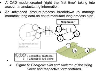
energetic surfaces (i.e. skins) connected by specific energetic skeletons. For further details, this Skin and
skeleton model is fully detailed in [12 & 18] and is very
similar to the skeleton [19] or “Working Pair Surfaces
and Channel” concepts given in [20]. Figure 5 gives the energetic skin and skeleton model concerning the CAD model of the Wing Cover given in figure 3. This model is only giving functional information (i.e. least commitment) without assuming what could be the manufacturing process that will be selected by the manufacturing expert. A1 Characterize interface model Design requirements Manufacture requirements A2 Select processes and identify manufacturing plans and their
constraints Materials requirements
List of manufacture processes alternatives Manufacturing processes List Humans resources : DFM Actor Humans resources : DFM Actor
List of plans alternatives List of manufacture processes
constraints Resources product-processes Resources product-processes Interface model (evolve in the synthesis loop)
Manufacturing constraints synthesis (data flow)
List of products alternatives solutions (definition of : geometry, tolerance, etc)
Design and manufacture requirements Attributes values of Manufacturing interface model
Attributes values of Manufacturing interface model
Figure 4: The DFM activity model.
4.1.2. Manufacturing process selection and information synthesis
From that usage Skin and Skeleton manufacturing expert can select the more adequate process plan that obviously have to respect the initial energetic
specifications. Actually, several manufacturing
solutions (i.e. alternatives) can be selected.
Manufacturing skins and skeletons are then used to
model the product-process interface and to generate the CAD models (or CAD alternatives) with respect to the process plan alternatives. Once again this CAD model is co-created using manufacturing information synthesis by least commitment (i.e. only with manufacturing constraints and no other constraint at this time).
5. PRODUCT-PROCESS INTERFACE TOWARDS
ADVANCED CAD MODELLING LINKED TO
MANUFACTURING DATA MANAGEMENT
This section gives the details of the product-process interface used in a DFM synthesis approach. As already introduced the added value lies in:
A CAD model created “right the first time” taking into account manufacturing information
An advanced product-process breakdown to manage manufacturing data on entire manufacturing process plan.
1 2 Wing Cover 3 Wing mechanical structure 1 2 3 3 1 2 « Energetic » Surfaces « Energetic » Skeletons
Figure 5: Energetic skin and skeleton of the Wing
Cover and respective form features.
5.1. Product-process interface modelling
The product-process interface model comes from the assumption that every manufacturing operation is based on a material flow called manufacturing skeleton in the following. This flow (or skeleton) (cf. Figure 6) is then defined with:
Sections defining the initial and final surfaces through which the material is going (i.e. transversal surfaces). A trajectory on which the material is formed.
An envelope surface which is generated. The link between envelopes generated in the process plan will provide manufacturing skins.
Flow trajectory Transversal initial surface Envelope surface Flow trajectory Transversal initial surface Envelope surface
Figure 6: Material flow (i.e. manufacturing skeleton) definition for product-process interface.
Based on that flow (called manufacturing skeleton) the material can be added (ex: injection), removed (ex: machining) or deformed (ex: forging, peen forming) to obtain the final part surfaces (called manufacturing skin). In the “added” and “removed” categories those surfaces are equal to the envelope surface.
Beyond very good results presented in [21] which concern the current results of that approach for nominal aspects, figure 7 gives the novelties of that paper. The new results concern the capabilities of that product-process interface:
To manage product tolerances coming from
manufacturing operations. Each level of tolerancing features (dimensional tolerances, form tolerances and roughness) is concerned. Figure 7 shows how those features are integrated in the product-process interface (i.e. manufacturing skeleton) characteristics.
To manage material heterogeneity coming from
manufacturing operations. It is also obvious that material flows (cf. above assumption) generate some gradients inside the manufactured product. Those gradients (ex: residual stresses) can, for instance, come from:
o Thermal phenomena in the skeleton’s sections that
come from a cooling phase which is not always homogeneous during casting operations.
o Mechanical deformation on the skeleton’s trajectory coming from forming processes (ex: forging, peen forming...).
The example of peen forming is given in the following section which is indeed one of the operations used to manufacture the Wing Cover. This example is also very interesting to show the added value of the approach with respect to manufacturing data management (cf. 5).
Figure 7: Example of product information issued from manufacturing process and managed by the
product-process interface.
5.2. Generation of advanced CAD model based on product-process interface
Keeping in mind both the CAD model presented in
figure 1 and the “by least commitment” CAD model
given in figure 5, the generation of an advanced CAD model which takes into account manufacturing plan is presented.
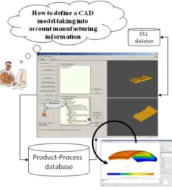
5.2.1. DFM_Synthesis plateform
This generation of the advanced CAD model is currently supported by a DFM_Synthesis platform that can be seen as a KBE application (Figure 8). The architecture of the software is made of:
A DFM_sythesis software that manages the product-process breakdown and the form features algorithms that generate the CAD model from manufacturing skeleton. The skin and skeleton data model of the KBE application is currently implemented using Open CASCADE Application Framework (OCAF) encapsulated in Microsoft Foundation Class objects and Open CASCADE geometric algorithms.
A product-process database that stores
information concerning the ID matrix presented in 3.2.1. This ad-hoc database is so far developed with MS Access. The identification is assumed, in this paper, to be already done. Three ways of identification are however treated: analytical
models, experimental data, and numerical
simulations.
A Finite Elements Analysis software that is used to assess the product topology (cf. 5.3.1). Indeed, as
previously presented, the product-process
interface model manages the heterogeneity coming from manufacturing operation that created residual stresses. Those residual stresses have to be treated at each step of the manufacturing process to calculate the elastic equilibrium of the entire part.
The “designers” is then using the DFM_Synthesis application which sends requests to the database in order to constrain the product parameters variability. The design is done “thinking of” manufacturing.
Figure 8: Overview of the KBE application.
5.2.2. CAD model generation scenario
Authors fully assume that the DFM_Synthesis scenario is processed by a manufacturing expert. There is no automatic process selection at all. Nevertheless, as already-introduced, the CAD model is co-generated once the process is selected. This manufacturing expert is then seen in this approach as a “designer”.
The expert therefore:
Realises the first mapping between product requirements and manufacturing processes. Shey matrix (cf. Figure 9) [22] is used to map initial partial CAD model (as presented in figure 5) to a manufacturing process list. Selects the first primary process from this list.
o The database therefore returns the process
parameters and a list of potential manufacturing skeleton features.
Selects one of the manufacturing skeletons and gives values to each parameter (i.e. process vector {PF}).
o The database returns the product values (i.e.
product vector {PD}) with respect to [ID] matrix.
o The open CASCADE algorithms generate the CAD
model according to the manufacturing skeleton features.
Figure 10 presents the manufacturing plan with regard to the Wing Cover already shown:
An extrusion operation as primary process. Extrusion tolerances are given by the product-process database and are integrated in the section of the extrusion skeleton that provides extra product information. Radius value of the section are also coming from the database to really take into account manufacturing constraints of the extrusion process (Step 1)
Three machining operations are then proposed by the manufacturing expert as secondary processes. (Step 2)
So far the final CAD module seems to be equal to a
classic CAD model. However, it has been
automatically generated while defining manufacturing plan and constraints. That is the main added value of the DFM approach. Other process plan alternatives could have been selected (cf. figure 11) that would then have generated other CAD alternatives.
A third peen forming operation is therefore defined and is presented in the following to focus on the residual stress. That is also one of the major issues tackled by the approach in order to link product and process information. This cannot be done using current commercial CAD software.
Figure 10: Illustration of the proposed DFM approach (from initial form feature to a complete CAD model).
5.3. Product-process interface for product and manufacturing data management
The final structure breakdown created actually gives
every product alternatives according to the
manufacturing alternatives (cf. breakdown tree in Figure 11). The solution is chosen by the manufacturing expert in the KBE application which then provides the respective CAD solution and respective material characteristics.
The evolution of the CAD model according to each manufacturing operation is then managed using the
product-process interface. This approach of
manufacturing data management is clearly an added-value facing the current commercial CAD software.
5.3.1. Product behaviour management
The first interest of managing product-process interface lies in the mechanical analysis of the
product. Product behaviour is indeed strongly related to material characteristics that are most often considered as homogeneous in the global volume of the part. Unfortunately, that homogeneity does not exist at all since most of manufacturing processes generate gradients of material characteristics (ex: forging, casting, shot peening, peen forming...).
Figure 11: OCAF structure for product and manufacturing process information management (example of the extrusion
operation among several alternatives).
Based on this KBE application it is then possible to know what is the exact initial state of the product (topology, quality, material heterogeneity) regarding each manufacturing operation. This initial state obviously encapsulates the product behaviour issued from previous manufacturing operations. Indeed each manufacturing interface (i.e.
manufacturing skeleton) gives that information.
Let us now talk about the Wing Cover part that should actually have a curved surface in order to fit fluid mechanic specifications. It is then possible to create a CAD model with respect to this curved surface but it does not make any sense without thinking of the manufacturing operation that physically generates that deformation. The proposed DFM_Synthesis approach then provides a great benefit for that.
The impact of material change (specifically residual stresses) based on manufacturing processes can be taken into account in the product-process interface (cf. Figure 12) and automatically processed to calculate the product deformation (cf. Figure 13). The Finite Element calculation is based on an elastic analysis of the part and the solver has to reach the global equilibrium of the residual stresses in it.
Since the KBE software manage the entire process plan, manufacturing expert acting as a designer can assess the product deformation with respect to each specific manufacturing operation (ex: extrusion, milling, peen forming) or to the entire process plan.
[x] x [y] : [ - 38 , 38 ] x [ -9,375 , 9,375 ] [x]spx [y]sp: [ - 38 , 38 ] x [ -9,375 , 9,375 ] e : « shell » ; [e] = [1,29] ep xx(z)= (z + 0,174)(0,0153 – 0,0753.z + 1,611.z2 ) ep yy(z)= (z + 0,174).(0,022 – 0,105.z + 1,93.z2 )
Manufa cturing skeleton « spherical shaped » x y [x] x [y] : [ - 38 + ? x , 38 - ? x ] x [ -9,375 + ? y , 9,375 - ? y ] [x]RSx [y]RS: [ - 38 + ? x , 38 - ? x ] x [ -9,375 + ? y , 9,375 - ? y ] e : « shell » ; [e] = [1,29 - ? e] R (x , y) : « bi-plane » ; [Rx] x [Ry] : [728 +/- ? Rx] x [581 +/- ? Ry] sR : « uniform » ; sR xx (z) .txt , sR yy(z) .txt
Manufacturing skin « spherical shaped »
sR (z) [x] x [y] : [ - 38 , 38 ] x [ -9,375 , 9,375 ] [x]spx [y]sp: [ - 38 , 38 ] x [ -9,375 , 9,375 ] e : « shell » ; [e] = [1,29] ep xx(z)= (z + 0,174)(0,0153 – 0,0753.z + 1,611.z2 ) ep yy(z)= (z + 0,174).(0,022 – 0,105.z + 1,93.z2 )
Manufa cturing skeleton « spherical shaped » x y [x] x [y] : [ - 38 , 38 ] x [ -9,375 , 9,375 ] [x]spx [y]sp: [ - 38 , 38 ] x [ -9,375 , 9,375 ] e : « shell » ; [e] = [1,29] ep xx(z)= (z + 0,174)(0,0153 – 0,0753.z + 1,611.z2 ) ep yy(z)= (z + 0,174).(0,022 – 0,105.z + 1,93.z2 )
Manufa cturing skeleton « spherical shaped » x y [x] x [y] : [ - 38 + ? x , 38 - ? x ] x [ -9,375 + ? y , 9,375 - ? y ] [x]RSx [y]RS: [ - 38 + ? x , 38 - ? x ] x [ -9,375 + ? y , 9,375 - ? y ] e : « shell » ; [e] = [1,29 - ? e] R (x , y) : « bi-plane » ; [Rx] x [Ry] : [728 +/- ? Rx] x [581 +/- ? Ry] sR : « uniform » ; sR xx (z) .txt , sR yy(z) .txt
Manufacturing skin « spherical shaped »
sR (z) [x] x [y] : [ - 38 + ? x , 38 - ? x ] x [ -9,375 + ? y , 9,375 - ? y ] [x]RSx [y]RS: [ - 38 + ? x , 38 - ? x ] x [ -9,375 + ? y , 9,375 - ? y ] e : « shell » ; [e] = [1,29 - ? e] R (x , y) : « bi-plane » ; [Rx] x [Ry] : [728 +/- ? Rx] x [581 +/- ? Ry] sR : « uniform » ; sR xx (z) .txt , sR yy(z) .txt
Manufacturing skin « spherical shaped »
sR (z)
Figure 12: illustration of manufacturing skeleton of a peen forming operation to embed residual stresses
information.
As presented in the figure 13, the main difficulty of the
calculation currently remains in “summing up” each
residual stresses field from every manufacturing operation.
Assuming that meshing is actually only used to solve the Finite Element Analysis, the authors argue the benefit of using the proposed product-process interface (i.e. manufacturing skeleton) to solve that issue. Manufacturing skeletons are, indeed, not based on meshing and the gradient of information can then be linked to the topological parameters that have a strong physical meaning for manufacturing experts. That is not the case of any meshes that are only dedicated to specific simulation models.
Keeping the link between manufacturing parameters and product information is very useful to notify every change concerning product definition. They can therefore be quickly propagated to manufacturing information without processing any new FEA.
The proposed solution based on the presented product-process interface is to link residual stresses field to each manufacturing skeleton. This is represented by topological features linked to manufacturing parameters (cf. figure 12); each skeleton being adequate for each material flow of the given manufacturing operation.
Figure 13: KBE and data management supporting field transfer for product deformation analysis. Finally, once the entire manufacturing process plan is defined and the respective product information (form + residual stresses field) is generated, all this
information can be exchanged with fatigue analysis software; which therefore takes into account the heterogeneity of the part to assess the global product behaviour.
5.3.2. Manufacturing data management for manufacturing process simulation
So far we have presented how product-process interface is used in a DFM approach for CAD modelling taking into account information of material heterogeneity (i.e. residual stresses - cf. figure 7) to better simulate product deformation according to the process plan.
Manufacturing data management via product-process interface modelling is actually also used to simulate each manufacturing operation (extrusion, milling, peen forming). Once again, process simulations very often assume the initial residual stresses as null whereas it is not the industrial and physical situation.
The proposed product-process interface is then also
interesting to “chain” every process simulation. Every
simulation can indeed integrate an initial state of residual stresses with respect to the history of previous operations of the process plan (ex: stresses coming from forging, casting…).
Figure 14 illustrates how product-process interfaces with respect to former manufacturing operation are used as input information in the following simulation of the peen forming process. The simulation is currently processed with Zebulon as Finite Elements solver.
The first manufacturing operation consists in extruding material that create the parallelepiped CAD model, attached tolerances and residual stresses as previously presented. The second operation is a peen forming operation. The ball impacts all the upper face and generates plastic deformations. This simulation of the peen forming operation solves the elastic spring-back of the entire part and provides the curve part. The final residual stresses gradient is integrated in the manufacturing interface model to be used for potential further manufacturing operations as milling or drilling for instance.
Figure 14: Illustration of transferring residual stresses embedded in skeleton from first manufacturing simulation to
the next one.
6. CONCLUSION AND RECOMMENDATIONS FOR
FUTURE WORK
This paper presents a product-process interface model for a DFM synthesis approach.
This model based on material flow modelling with respect to skeleton and skin concepts is first used to integrate manufacturing information as soon as possible in the product design process (i.e. “by least commitment design approach”). This integration strongly leads the CAD modelling and by the
way centres the design process on expert designers’ knowledge and not on form features any more. The second objective of that interface model is to manage manufacturing information linked to product characteristics (ex: topology, tolerances, residual stresses…). It is then profitable to simulate manufacturing processes taking into account the evolution of the product characteristics with respect to the manufacturing plan. The whole history of each manufacturing operation is then linked to the product definition that is not currently the case in CAD-centred design approach.
The main recommendations for future work are: The application of the KBE software to more
complicated academic and industrial case studies.
The implementation of product-process
relationships database that could further take into
account more manufacturing physical and
technological phenomenon that are already-known; for instance vibration, or dynamic behaviours during machining operations.
7. ACKNOWLEDGMENTS
This research work is partly supported by SNECMA industry. It is part of the MAIA project.
The experimental peen forming process on the Wing
Cover part has been carried out in the Sisson
Lehmann (Wheelabrator group) industry.
8. REFERENCES
[1] Liu W., Matez M., Zeng Y., Brisson D., 2009,
Product Lifecycle management: a review, Proceedings of the ASME 2009 International Design Engineering Technical Conferences & Computers and Information in Engineering Conference IDETC/CIE 2009, August 30-September 2, 2009, San Diego.
[2] Tomiyama T., Gu P., Jin Y., Lutters D., Kind Ch.,
Kimura F., 2009, Design methodologies:
Industrial and educational applications, CIRP Annals - Manufacturing Technology (2009), doi:10.1016/j.cirp.2009.09.003
[3] Gero, J S., 1990, Design prototypes: a
knowledge representation schema for design, AI Magazine Vol 11 No 4 (1990) 26–36
[4] Suh N., Suh N.P., 1999, Applications of
Axiomatic Design », Integration of process Knowledge into Design Support, ISBN 0-7923-5655-1, Kluwer Academic Publishers.
[5] Andreasen M., Hein L., 1987, Integrated product
development, Springer-Verlag, London, 1987.
[6] Tichkiewitch S., 1996, Specification on integrated
design methodology using a multi-view product model, ESDA Proceedings of the 1996 ASME System Design and Analysis Conference, PD-Vol. 80, pp. 101-108.
[7] Krause F.-L., Kimura F., et al., 1993, Product
Modelling. Annals of the CIRP 42(2).
[8] Yan X.-T., 2001, A multiple perspective product
modeling and simulation approach to
engineering design support, Concurrent
Engineering Research and Application Journal (CERA): 221-234.
[9] Roucoules L., Lafon P. et al. 2006, Knowledge intensive
approach towards multiple product modelling and geometry emergence to foster cooperative design. Proceedings of the CIRP Design seminar, Kananaskis. [10] Roucoules L., Tichkiewitch S., 2000, CoDE: a
Co-operative Design Environment. A new generation of CAD systems. In Concurrent Engineering Research and Application Journal (CERA) 8(4): 263-280.
[11] Tichkiewitch S., Roucoules L., 1999, Methodology for innovative design, CIRP Design Conference, Twente (NL).
[12] Klein Meyer J.S, Roucoules L., De Grave A. and Chaput J., 2007, Case study of a MEMS switch supported by a FBS and DFM framework. In proceedings of the 17th CIRP Design Conference, Berlin. ISBN 978-3-540-69819-7.
[13] Boothroyd G. et al., 1994, Product design for manufacture and assembly. Marcel Dekker, ISBN 0-82479-176-2.
[14 ] Swift K.G, Brown N.J, 2003, Implementation strategies for DFM, Journal of Engineering Manufacture, vol.217, p. 827-833.
[15] Cagan J., Campbell M., Finger S., Tomiyama T., 2005, A Framework for Computational Design Synthesis: Model and Applications, Journal of Computing and Information Science in Engineering SEPTEMBER 2005, Vol. 5.
[16] Zhao Z., Shah J., 2005, Domain independent shell for DfM and its application to sheet metal forming and injection molding, Computer-Aided Design, Volume 37, Issue 9, August 2005, Pages 881-898.
[17] Cochennec F., Roucoules L., Rouhaud E., 2006, Mechanical Analysis to identify knowledge for a DFM approach. Application to Shot Peen-forming process. In Proceedings of Virtual Concept 2006 conference, Playa Del Carmen, Mexico.
[18] Roucoules L., Skander 2003, A. Manufacturing process selection and integration in product design. Analysis and synthesis approaches. Proceedings of the CIRP Design seminar, Grenoble (Fr).
[19] Muh-Cerng Wu., Wu T.Y., 1993, A skeleton approach for modelling assembly products. In Journal of Design and Manufacturing. 3: 121-133.
[20] Albers A., Braun A., Clarkson J., Enkler H.G., Wynn D., 2009, Contact and channel modelling to support early design of technical systems, International Conference on Engineering Design, Iced'09, 24 - 27 august 2009, Stanford university, Stanford, USA.
[21] Skander A, Roucoules L., Klein Meyer JS, 2008, Design
and manufacturing interface modelling for
manufacturing processes selection and knowledge synthesis in design. In International Journal of
Advanced Manufacturing Technology, DOI
10.1007/s00170-007-1003-2, n°37, 2008.
[22] Schey J., « Introduction to manufacturing Processes », McGraw-Hill, Co., Singapore, 1987.