HAL Id: hal-02095941
https://hal-amu.archives-ouvertes.fr/hal-02095941
Submitted on 22 May 2020
HAL is a multi-disciplinary open access
archive for the deposit and dissemination of
sci-entific research documents, whether they are
pub-lished or not. The documents may come from
teaching and research institutions in France or
abroad, or from public or private research centers.
L’archive ouverte pluridisciplinaire HAL, est
destinée au dépôt et à la diffusion de documents
scientifiques de niveau recherche, publiés ou non,
émanant des établissements d’enseignement et de
recherche français ou étrangers, des laboratoires
publics ou privés.
Embedding intelligent image processing algorithms : the
new safety enhancer for helicopters missions
Zoppitelli Pierre, Sébastien Mavromatis, Jean Sequeira, Guillaume Anoufa,
Nicolas Belanger, François-Xavier Fillias
To cite this version:
Zoppitelli Pierre, Sébastien Mavromatis, Jean Sequeira, Guillaume Anoufa, Nicolas Belanger, et al..
Embedding intelligent image processing algorithms : the new safety enhancer for helicopters missions.
44th European Rotorcraft Forum - ERF 2018, Sep 2018, DELFT, Netherlands. �hal-02095941�
Paper 130
EMBEDDING INTELLIGENT IMAGE PROCESSING ALGORITHMS: THE NEW SAFETY
ENHANCER FOR HELICOPTERS MISSIONS
Pierre Zoppitelli, [email protected], Airbus
Sébastien Mavromatis, [email protected], Aix Marseille Université Jean Sequeira, [email protected], Aix Marseille Université
Guillaume.Anoufa, [email protected], Sogeti HighTech Nicolas Belanger, [email protected], Airbus François-Xavier, [email protected], Airbus
Abstract
Over the last two decades, image processing technologies rapidly emerged from the shadows to become one of the most important field of interest in computer science. Although image analysis is a hot topic in the automobile industry and for some aircraft applications (drones, airplane, space probes...), the certification of any vision based autopilot system for helicopter missions remains an ongoing challenge. Indeed, such a system would be required to perform complex missions with a high success rate while possibly facing adverse weather conditions. However the rapid increase of processing power, the development of image analysis algorithms, as well as the miniaturization of high resolution cameras, are allowing new technical solutions for autonomous flight. Facing this new technological deal, helicopters manufacturers can no longer ignore that vision based systems are about to become a key enhancer for versatile rotorcraft missions. Airbus Helicopters is committed to put the safety of its aircrafts at the highest standards. For this purpose, Airbus Helicopters has initiated the development of advanced systems integrating many disciplines like sensor acquisition, scene understanding, situation awareness, and artificial intelligence. As a contribution to this company objective, the EAGLE project (Eye for Autonomous Guidance and Landing Extension) was launched 2 years ago to develop a generic optronic platform facilitating integrations of algorithms for different applications. The system aims to improve safety and reduce the pilots’ workload during flights in oil and gas and SAR missions. This paper presents the latest results that have been obtained by Airbus Helicopters and the LIS-lab in the development of a landing platform detector in the frame of this project. We will first introduce the general methodology applied for the determination of the platform position. The approach is hierarchical and based on a collection of hints to determine, refine and validate suitable locations for the presence of a helipad. We will then present the strategy for the selection of regions of interest. The aim is both to determine the right size of portion of the image to be analyzed, and to enable the real-time adaptation of the selection and sequencing of the regions to be explored.
This article will then detail the methods used to determine the areas susceptible to contain a landing platform. The algorithm mainly relies on flat ellipse detection as it is the most visible feature of a helipad seen from long distances. An adaption of the Hough transform proved to be the most reliable method in the specific case of very flat ellipses. A validation step using many other properties and visual clues performs the verification of the presence of the helicopter landing platform in the research areas delimited by the obtained ellipses. Having presented the algorithm for the detection of a helicopter landing platform, we will discuss some approaches to increase the system’s accuracy, robustness and integrity (detection of failure). In particular, safety and certification considerations are used to select the human-machine interfaces and overall design of the system. A result section will show how this system demonstrated to be capable of detecting landing platforms from a distance of 1500 meters and tracking it without interruption until the landing phase. Last but not least, this paper will introduce an open view of identified image processing technologies continued path for the upcoming years. Our vision of this technological field as a mandatory brand new core competency to be strengthened within Airbus Helicopters, and the way we intend to build up the necessary ecosystem with Airbus’ other business units, will be the epilogue of the article.
Paper 130
1. OVERVIEW 1.1. Introduction
As drones’ autopilots are becoming more and more complex, the field of possible missions is getting larger and larger: drones may now deliver packages, they monitor large portions of territorial waters, also spread fertilizers over crops and do many other different and difficult tasks. It would be natural to expect that helicopters would follow the same path towards completely autonomous missions. However, many challenges proper to the helicopter Industry needs be solved: some missions tend to be extremely demanding (search and rescue, transportation to offshore platform) and safety and certifiability concerns are of the utmost importance.
To achieve this goal, a complex system of sensors is required. Indeed, a drone has to be able to assess a situation before making any decision. Among the possible sensors we may cite: day and night cameras, infrared sensors, LIDAR, RADAR, and GPS. There is also the solution to have the sensors in a ground station instead of on-board the aircraft. In the frame of the EAGLE project the solution chosen was to have a set of cameras mounted on the helicopter. It has the advantage to be cheaper than LIDAR and RADAR solutions while not requiring the installation of specific systems on a ground station. GPS cannot be used alone as it requires the communication with other systems and lacks the precision to handle most missions.
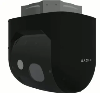
Fig 1: The EAGLE system.
1.2. General methodology
Our algorithm is based on human perception. It is divided into many processes with limited scope. Each process has a single task with one clearly defined objective. At each step of the algorithm we look for visual properties verified by the desired object in order to remove all candidates who do not have those properties. We continue this process until only the desired objects remain. It is very important that none of the tasks remove a correct candidate. This approach has several advantages: it is always possible to know at which point the algorithm failed, it is easy to improve (we know the expected results at each step), we need limited data to start working (we may add some steps to tackle new difficult problems) and it is easier to prove that the algorithm has found a correct solution.
A landing platform which follows the norm described in the CAA (Civil Aviation Authority) CAP437 must have a thick yellow circle painted on a green platform; moreover, a white "H" is painted at the centre of the circle. The authorized lengths of each one of these elements are described in this document. We can assert that there are a few important visual properties: the circle which will be seen as an ellipse from afar, the presence of the H at the centre of the circle, the homogenous regions of the same colour. We can also expect that the landing platform will be on an offshore rig which will be heavily contrasted compared to the uniform sea landscape. It would be too time consuming to search for all visual clues in the whole image; instead, we focus on the most dominant visual clues which allow us to identify interesting regions or portions of the image to which we apply more compute-intensive algorithms.
The proposed methodology for the detection of a landing platform in sea background includes the following steps: first, we locate potential oil platforms, then in these areas we will search for ellipses to define very precise regions of interest and eventually we validate the presence of the helipad with all visual clues available (homogenous colours, presence of the H, etc...). This approach mimics how the human vision operates; first, we search for something that looks like the desired object, then we focus our attention into it, and finally we determine if it is indeed the sought object.
2. THE DETECTION OF THE LANDING PLATFORM
2.1. Related work
Several papers about helipad detection techniques have been published for the autonomous landing of drones [12-15]. However, none of these addresses the specificities of the landing of helicopters. In particular, many common hypotheses made by the authors do not hold for the application domain we are targeting:
• They assume the helipad is viewed directly from above and not masked by other structures
• They do not take into consideration safety and certification requirements of helicopter systems
• They assume the videos are of good quality and taken in favourable lighting conditions.
As all these limitations cannot be disregarded for our application, we need to look for new solutions. These innovative methods should be able to detect helipad in difficult conditions such as grazing angle views, very far helipad and low quality images.
Since a helipad consists of an H within a circle and circles are transformed into ellipses by perspective projection, the largest visual clue of the presence of the helipad will be a flat ellipse. We chose to decompose our landing platform detector algorithm into two steps: first we look for potential helipad candidates by searching ellipses in the image; then, we verify for each candidate ellipse if there is a helipad at this location.
To detect potential helipad candidates, several techniques, based on ellipse detection, are available. They can be classified into several categories:
• Curve fitting techniques • Arcs grouping methods • Active contour techniques • Hough transforms approaches
Let us detail briefly the advantages and drawbacks of each category of solutions.
Curve fitting methods are very efficient, but they fail when there is a large number of points of the processed image which do not belong to the ellipse. The most used technique is based on the least square optimization technique [2]. Several advances have increased the resistance to outliers; however, the limitation still exists.
The adjacent arcs and lines grouping method consists of linking edges to produce arcs and then merging arcs belonging to the same ellipse. It was first described by Kim et al. [11]. Jia et al. [1] improved this method by using a projective invariant that allows them to quickly assess if two arcs have to be merged. These techniques produce good results even for very complex images with a multitude of ellipses. However they fail when the ellipses are heavily occluded, dashed or extremely flat.
Active contours techniques let evolve an elliptic curve under some constraints. One major problem of these methods is their inability to deal with complex images: the contours may converge to suboptimal solutions.
The methods relying on the Hough transform ([5], [10]) map the input image into a parametric space and then take the peaks in this space as candidates for the ellipse. The principle of the Hough transform is to explore all minimal combination of points that produce a parametric model and count how often each model appears. For example, when used to detect ellipses, five points are required to determine an unique ellipse and by exploring all combination of five points we may see which ellipses are recurrent and thus which ellipses are in the image. In practice, a five point Hough Transform is very inefficient and solutions had to be found to reduce the complexity of the approach ([10], [6]).
Hough transforms are very effective even on the most difficult conditions. They can produce good results with partial, flat or dashed ellipses as it was proven in [16]. On the other hand, they are compute-intensive and difficult to parametrize even though several advances have reduced these shortcomings.
To solve our problem, we chose the Hough transform approach, as it is the only one robust enough to address the specificities of the helicopter domain. Furthermore, several techniques are available to reduce processing time:
• Reduction of algorithm complexity by separating the computation of the parameters [6],
• Hardware specific parallelization techniques (GPU/FPGA) ([3], [4]),
• Data reduction by using a multi-resolution or sub sampling approach ([9], [16]).
The following sections will describe the proposed helipad detector algorithm. They will comprise: the methodology adopted for the selection of the portion of the image to be analysed, the detection
of potential helipad candidates through the research of ellipses, and, the checking of the presence of the helipad at the location of each candidates.
2.2. Selection of the regions of interest
In this section, we present the method to select the right portion of the image to be more deeply analyzed. We first describe an algorithm to extract the oil & gas platform from the image, and then we propose a method to select the region of interest based on many factors like computation time and previous results of the detection algorithm.
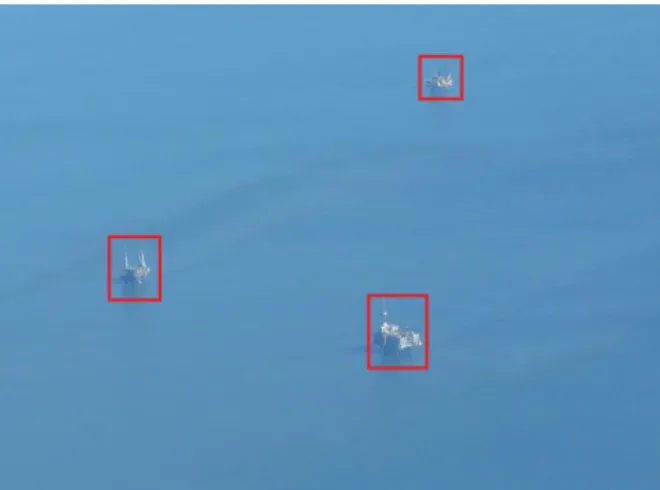
To reduce the portion of the image to be analyzed we remove the sea background in the image. The segmentation procedure is based on texture analysis and on two properties of the sea texture in the image. The sea is preponderant in the image and it is lightly contrasted compared to the sought entities (oil & gas platforms). Haralick proved that the texture of an image could be described by the statistical relationships between neighbor pixels [8]. He proposed a set of features to extract some visual properties from those statistical relationships; those features include contrast, homogeneity, variance, correlation and many others. Our algorithm uses the contrast texture descriptor and an automatic segmentation method to precisely locate the offshore platforms (see Fig 2).
Fig 2: The detected platforms using Haralick features.
However, once the helicopter is getting close to the oil & gas rigs, the platforms can take a huge portion of the image which would make the exhaustive research of landing platforms difficult. Instead of spending a lot of time and resources to produce a solution capable of detecting all kind of platforms in all kind of images, we developed an
algorithm which only detects the landing platform on very specific conditions; and we adapt (by cutting or resizing) the input image to fit those criteria. Basically, we transform a difficult problem into a set of smaller and easier problems. More precisely, we have an algorithm that can only detect a landing platform whose size is comprised between one half and one sixth of an image with a fixed width and height; we decompose the portion of the image encompassing the rig in a multitude of sub-images which will be then resized to fit the above criteria. By using a multi-resolution approach, the algorithm is able to find both small and big landing platforms in the image.
Fig 3 : The resizing of the sub-image to fit the criteria.
Fig 4: The multi-resolution approach. The input image is divided into many overlapping sub-images.
The multi-resolution approach provides several advantages. We do not have to adjust the parameters to handle specific edge cases: every problem comes down to solving the same simple problem. Another desirable feature is the bounded computation time; this is due to the fixed size of sub-images to be examined. Finally, one major advantage of the solution is to allow the parallelization of those processes: the computation of one sub-image is independent to the one of another which massively reduces the overall computation time on parallel architecture.
Even though the computation time has been significantly reduced thanks to the previously described techniques, we still cannot process all the sub-images at each frame. We therefore define a priority list which organizes the list of sub-images based on previous results of the detection algorithm. For example, if a sub-image produces a positive result it is sent to the top of the priority list and the detection will be done at each frame. On the other hand, if we are certain that there isn't anything interesting in the sub-image, it will be sent to the bottom of the priority list, and the computations on this area will be done at a lower frequency than the video frame rate.
2.3. The selection of potential helipad through the research of ellipses
In this section, the techniques used to locate the region of interests likely to contain a landing platform will be described. First, will be detailed the techniques used to extract the pixels likely to belong to the circle of a helipad. Then the Hough transform and the techniques used to obtain the candidate ellipse centre will be presented. Lastly, the methodology for the reconstruction of the ellipses will be described.
Fig 5: Input sub image used for the testing.
Several image pre-processing techniques are used before applying the Hough transform to improve the signal to noise ratio. They are all based on visual properties of the helipad. These processes include:
• A high-pass filter to extract the edges of the image as we look for the contours of the ellipse,
• A texture-based filter, since the helipad is homogenous around the circle,
• A colour separation scheme, as all points of the circle of the helipad have the same
colour,
• A speckle noise filter to remove sparse points.
Fig 6: The binary image.
For each Hough transform, we need a function that maps a set of points to a model. Instead of using five points to compute all five parameters of the ellipse at once (which is costly), we chose to use only three points and compute only the centre of the ellipse. Let us describe the property of tangent lines of conics that we employ to compute the ellipse centre.
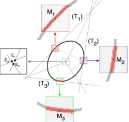
7: A property of ellipses. C, M and T are on the same line.
If P and Q are two points of an ellipse with M the middle of [PQ] and T the intersection of the tangents passing through P and Q, then the centre C of the ellipse is on the line passing through M and T.
We may combine this property with a Hough transform to compute the ellipse centres of the image. We can improve furthermore this method to increase the signal to noise ratio. When we apply this property to two points, we assume that they belong to the same ellipse which is most likely not the case. In order to check that the computed centres are valid, we may use three
points instead of two and verify that the three lines intersect close to a unique point (the centre).
Fig 8: When three points belong to a same ellipse, the three lines form a very small triangle close to the centre.
We may further refine the centres by looking at the orientation of the arcs around the tangent. If three arcs belong to the same ellipse, each one of them should face the computed centre.
Fig 9: Example of badly oriented arcs.
Fig 10: Computed centre using the Hough transform. Once the ellipse centres are detected, we need to find the remaining parameters which are the two axes and the angle. To produce the desired ellipses, we group points that voted together for
the centre while also grouping those that are close spatially. The main idea is that if almost every triplet of points from one subset produced the same centre, then they are likely to be part of a unique ellipse. A method of ellipse fitting is applied to each subsets of points to produce the same number of ellipses. We then merge the ellipses that have similar parameters.
The selection of the best candidate ellipse is based on two criteria: the completeness of the ellipse and the resemblance to an ellipse. To evaluate the first criterion, we compute the expected number of points of the ellipse (if it were complete) and we compare it to the total number of points used in the ellipse fitting process. The second descriptor is computed by evaluating the dispersion of the pixels around the ellipse.
After the best ellipses are selected, we need to verify if they belong to a helipad. These validation steps are detailed in the next section.
Fig 11: The computed best ellipse.
2.4. The validation of the candidate helipads
In the previous section, we presented the methods used to obtain a set of regions of interest through the research of ellipses in the image. Since the portion of the image to be analyzed is heavily reduced after this first phase of image processing, we may perform some compute-intensive processing. The clues used to perform the validation of the landing platform are:
• Detection of the inner and outer contours of the circle of the helipad
• Verification of the coherence of the colors of each region of the helipad
• Detection of the H inside the circle
The first validation step of the helipad is the detection of the elliptic ring of the helipad. From the areas of the ellipses previously detected, we can define an enlarged zone in which we can look
for the inner and outer contours of the helipad elliptic ring. The collected points of these boundaries can then be processed with curve-fitting algorithms based on the least-square method. We may then check that the detected ellipses correspond to those of a helipad: they should have the same center and orientation.
Fig 12: The enlarged research zone in light red. And a specific research zone in orange.
Fig 13: The inner and outer ellipses of the helipad elliptic ring.
In the following validation step, we check the coherence of the colors of the different areas of the helipad. Thanks to the previously identified contours, we can define 3 different zones: the inner part of the circle, the outer part and the circle itself.
We then verify that each of these areas has homogeneous color distribution and that the color inside the circle is different from those of the other areas.
Fig 14: The three regions that need to be examined.
The last step of our validation process is the detection of the “H” in the inner area of the circle. However, depending on the distance of the camera to the helipad, the “H” may be more or less visible and sometimes barely detectable. In order to make the best use of available information and get the most reliable method of helipad detection, we chose to have two different methods for the validation of the presence of the “H”. Each one tailored to the size of the helipad in the processed image.
When the « H » is barely visible, we rely on an implicit detection method based on a skeletonization process and the usage of 2D shape descriptors (perimeter, surface, number of holes, etc). This is due to the fact that we cannot extract the complete H structure and we can only assess the global shape of the H.
When the « H » is clearly visible, we determine its boundaries with line detection techniques. We then verify that the detected lines can be classified into two sets of parallel lines and that when joined they form the shape of an H.
3. IMPROVING THE OVERALL SAFETY BY INTELLIGENT DESIGN SOLUTIONS
The final objective of the system Airbus is developing is to enable the safe automatic landing of a helicopter on an offshore platform. As for any system, Airbus Helicopters follows ARP4754 methodology to describe the system in terms of functions and analyse the consequences of function failures. Wrong helipad position determination can lead to a catastrophic event, and for this reason the functions developed require very stringent reliability performance or mitigations factors to insure the safety of the system.
To provide the most reliable autonomous landing system we propose a set of principles that we divide into three categories: multiple independent validation steps within the algorithm, automatic real-time verification of the results outside of the algorithm and lastly validation and supervision through interaction with the pilot.
Within the algorithm, the methodology to decrease the chance of producing a false alarm relies on several independent validations steps mentioned in the section 2.1.4. We will quickly remind all those requirements. The first one is to have two concentric circles on an area. Then, the colours of the circle and the surrounding area should match that of a landing platform. Furthermore, the inner area of the circle should have an H. Thus, for a false detection to be validated, the object needs to have all the properties of a helipad while not being a helipad which is extremely unlikely. We also propose several solutions to automatically detect when the system fails to detect the desired objects. A generic 2D tracking system provides an independent method to predict the position of the helipad in the screen at each frame. By comparing the results of the 2D tracking with those of the landing platform detector, it is possible to verify that the system is indeed tracking the desired object. By extension, we may know in real-time when the detection starts to produce incorrect results. Additionally, the AFCS verifies that the real-time evolution of the computed relative position of the helipad is coherent with the 3D motion of the Helicopter. This enables another independent verification of the provided results.
To reduce the criticality level of the functions implemented, our system includes a human machine interface that mitigates the risk of false detections. A symbology is presented to the pilot that enables him to validate in real-time the results
given by our algorithm. Additionally, the pilot only can trigger the coupling of the system with the AFCS, which means that the automatic landing mode will be only activated when the pilot is certain that the provided information is reliable.
4. TESTING THE HELIPAD DETECTON ALGORITHM ON DIFFICULT IMAGES
In the following section, we will present the results obtained with the detection algorithm on images chosen to accurately represent the most difficult conditions our system is expected to face. These include: rapidly moving cameras, vibrations, and very low contrast.
Five images were used. For each one of them we present the results obtained in the full image and in a zoomed image of the helipad with the inside and outside contours displayed.
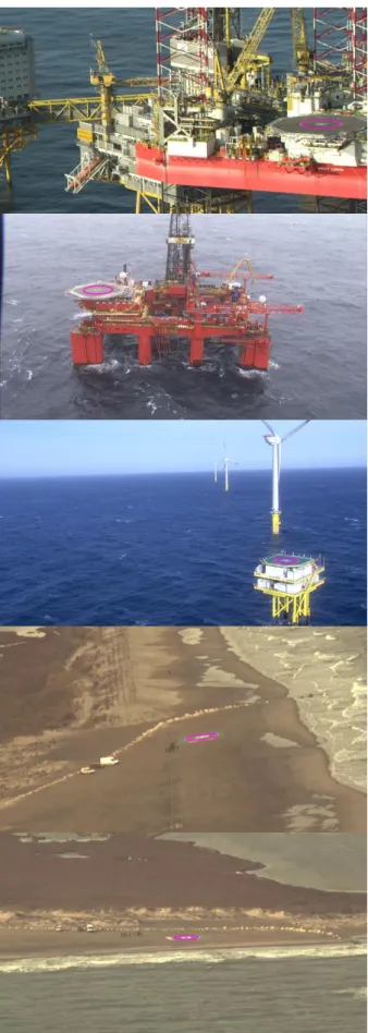
The first three images were taken from videos provided by offshore operators as the cameras of our system were still being specified. The last two images were captured by the EAGLE system on flight. We will quickly describe the difficulties of each image presented.
Let us first describe the images provided by our offshore partners. The first image was taken during an approach for an oil & gas transport mission. The image is blurry due to the rapid movement of the camera. The sensor quality is low and the helipad has a much lower contrast than the rest of the offshore rig. The second image has the worst overall contrast as the lighting conditions were extremely poor during the recording. The third one was taken during the maintenance of wind turbines; its difficulty is much lower than the two previous images. However, we can see that the colours of the helipad have shifted to the green.
The last two images were taken with the EAGLE system. They were taken from very far (above one km) with a low angle camera and consequently the vibrations are much more perceptible while the colours have less variations. The fourth image was taken with a forbidden approach direction landmark in front the helipad; this severely reduces the portion of the elliptic ring to be detected. The last image was taken during an advance towards to the landing platform. The approach angle is estimated to be under 7° while the helipad was at a distance farther than 1500m.
Fig 16: Detection results in the full image.
Fig 17: Inside and outside contours for each previously shown image.
We can see (Fig 16) that our algorithm is able to detect the helipad even for the most difficult conditions. We can also note (Fig 17) that the detection has a high accuracy. The detected contours of the helipad are very precise despite the blurry and little contrasted images.
5. CONCLUSION AND PERSPECTIVES
Significant progress in the detection of helipads has been achieved in the frame of the EAGLE project to allow safe helicopters automatic landing on offshore platforms.
It has been shown that techniques and algorithms already available for the detection of norms compliant helipads have shortcomings and that innovative computer vision methods had to be developed to enable a robust automatic detection of helipads in representative environmental conditions. Specific difficulties had to be addressed:
Detection of helipads with grazing angle views and adverse weather conditions, Real time and hardware specific constraints,
Compliance to stringent safety requirements and certification rules of the rotorcraft industry.
The innovation of our methodology relies on a set of requirements or criteria that a platform should abide to. First we look for ellipses in the image as it is the most visible property of the landing platform. Then we search for the other visual features at each potential location of the helipad. Each criterion, when observed, reinforces the probability that the detected object is indeed the researched landing platform. Consequently, relying on a high number of criteria makes wrong detection hardly possible.
Our system was evaluated with videos obtained by the EAGLE optic system to provide the most representative conditions of real operations through tests which demonstrated remarkable detection performance:
• Efficient detection from distances above 1500m with a 7° approach angle,
• High precision of 3D pose estimation, differences to the ground truth lower than 3% of the distance to the helipad,
• Every helipad, once detected, is tracked until the landing of the helicopter.
Having validated the system performance on conditions representative of real operations, the next step will be to test the system on real-time situations. This requires the integration of the various algorithms on a platform linked to the optronic system, namely: the ellipse detection, the image stabilization software, the generic 2D tracker and the supervisor. A human machine interface is also being developed and a direct link with the automatic flight control system is to be implemented. It will enable the execution of automatic landings with minimal interactions with the pilot.
To continue our investigations in this domain and ensure that our system is effective even in the worst possible environmental conditions, we will test our algorithms with data generated by a 3d
graphic engine. Indeed a simulation environment will enable the assessment of our system’s performance over a wider range of environmental and flight conditions at a low cost and a fast paced development.
Recent breakthroughs in image processing are providing new perspectives for flight safety. We can imagine, in the near future, systems combining information from different sensors (GPS, IMU, computer vision) for automatic ship deck landing, emergency landings, hoist operations, collision avoidance and many others. Computer vision is expected to have more and more applications in the near future as progress in algorithms and hardware processing power are expected to continue at an ever increasing pace. In the automotive industry, computer vision is already very present in different ways: autonomous vehicles, emergency braking systems, automatic parking…
As the helicopters industry is now very mature and few breakthroughs are expected in the mechanical or structural domains, the development of systems, and in particular computer vision-based systems, will become key differentiating features.
It is expected that the coupling of these and other systems to the automatic flight control system will revolutionize the way helicopters and drones will fly in the future. For this reason, it is of the utmost importance for Airbus Helicopters to secure a leading role in the development of new vision systems and their software.
6. REFERENCES
[1] JIA, Qi et al. (2017). « A Fast Ellipse Detector Using Projective Invariant Pruning ». In : IEEE Transactions on Image Processing 26.8, p. 3665– 3679.
[2] FITZGIBBON, Andrew, Maurizio PILU et Robert B. FISHER (1999). « Direct Least Square Fitting of Ellipses ». In : IEEE Trans. Pattern Anal. Mach. Intell. 21.5, p. 476–480.
[3] BRAAK, Gert-Jan van den et al. (2011). « Fast Hough Transform on GPUs : Exploration of Algorithm Trade-Offs ». In : Advanced Concepts for Intelligent Vision Systems. Springer Berlin Heidelberg, p. 611–622.
[4] TAGZOUT, Samir, Karim ACHOUR et Oualid DJEKOUNE (2001). « Hough transform algorithm for FPGA implementation ». In : Signal Processing 81.6, p. 1295–1301.
[5] HOUGH, P. V. C. (1959). « Machine Analysis of Bubble Chamber Pictures ». In : Conf. Proc. C590914, p. 554–558.
[6] YUEN, H.K., J ILLINGWORTH et J KITTLER (1989). « Detecting partially occluded ellipses using the Hough transform ». In: Image and Vision Computing 7.1, p. 31–37.
[7] ZHANG, Si-Cheng et Zhi-Qiang LIU (2005). «A robust, real time ellipse detector» In Pattern Recognition38.2,p.273– 287.
[8] Haralick, Robert & Shanmugam, K & Dinstein, Ih. (1973). Textural Features for Image Classification. IEEE Trans Syst Man Cybern. SMC-3. 610-621.
[9] CHIEN, Chung-Fang, Yu-Che CHENG et Ta-Te LIN (2011). « Robust ellipse detection based on hierarchical image pyramid and Hough transform ». In: Journal of the Optical Society of America A 28.4, p. 581.
[10] TSUJI et MATSUMOTO (1978). « Detection of Ellipses by a Modified Hough Transformation ». In: IEEE Transactions on Computers C-27.8, p. 777–781.
[11] KIM, Euijin, Miki HASEYAMA et Hideo KITAJIMA (2002). « Fast and Robust Ellipse Extraction from Complicated Images ». In: Proceedings of the IEEE International Conference on Information Technology and Applications. [12] Lee, Sewon & Jang, Jinwon & Baek, Kwangryul. (2012). « Implementation of vision-based real time helipad detection system ». International Conference on Control, Automation and Systems. 191-194.
[13] Cosimo Patruno, Massimiliano Nitti, Ettore Stella, and Tiziana D’Orazio 2017 « Helipad detection for accurate UAV pose estimation by means of a visual sensor » International Journal of Advanced Robotic Systems
[14] Prakash, R Om & Chandran, Saravanan. (2016). “Autonomous Robust Helipad Detection Algorithm Using Computer Vision”. 10.1109 / ICEEOT 2016 7755163.
[15] A. Rodriguez-Ramos, C. Sampedro, H. Bavle, Z. Milosevic, A. Garcia-Vaquero and P. Campoy, "Towards fully autonomous landing on moving platforms for rotary Unmanned Aerial Vehicles," 2017 International Conference on Unmanned Aircraft Systems (ICUAS), Miami, FL, USA, 2017, pp. 170-178.
[16] P. Zoppitelli, S. Mavromatis and J. Sequeira (2017). “Ellipse detection in very noisy environment”. In : Proceedings of the Computer Science Research Notes [CSRN] 2703 ISSN
2464-4617, International Conference in Central Europe on Computer Graphics, Visualization and Computer Vision 2017 p. 31–40.
[17] BASCA, C.A., M. TALOS et R. BRAD (2005). « Randomized Hough Transform for Ellipse Detection with Result Clustering ». In: EUROCON 2005 - The International Conference on "Computer as a Tool"