HAL Id: tel-01829962
https://hal.laas.fr/tel-01829962
Submitted on 4 Jul 2018
HAL is a multi-disciplinary open access archive for the deposit and dissemination of sci-entific research documents, whether they are pub-lished or not. The documents may come from teaching and research institutions in France or abroad, or from public or private research centers.
L’archive ouverte pluridisciplinaire HAL, est destinée au dépôt et à la diffusion de documents scientifiques de niveau recherche, publiés ou non, émanant des établissements d’enseignement et de recherche français ou étrangers, des laboratoires publics ou privés.
A distributed modular self-reconfiguring robotic
platform based on simplified electro-permanent magnets
Li Zhu
To cite this version:
Li Zhu. A distributed modular self-reconfiguring robotic platform based on simplified electro-permanent magnets. Networking and Internet Architecture [cs.NI]. Universite Toulouse 3 Paul Sabatier (UT3 Paul Sabatier), 2018. English. �tel-01829962�
TH `
ESE
TH `
ESE
En vue de l’obtention du
DOCTORAT DE L’UNIVERSIT´
E DE TOULOUSE
D´elivr´e par : l’Universit´e Toulouse 3 Paul Sabatier (UT3 Paul Sabatier)
Pr´esent´ee et soutenue le Vendredi 16 f´evrier 2018 par :
LI ZHU
A distributed modular self-reconfiguring robotic platform based on simplified electro-permanent magnets
JURY
Nadine Le Fort Piat Professeur Universit´e de Bourgogne, Franche-Comt´e
France Julien Bourgeois Professeur Universit´e de
Bourgogne, Franche-Comt´e
France Patrick Danes Professeur Universit´e de Toulouse
III Paul Sabatier
France Didier El Baz Charg´e de Recherche CNRS,
LAAS-CNRS
France
´
Ecole doctorale et sp´ecialit´e :
MITT : Domaine STIC : R´eseaux, T´el´ecoms, Syst`emes et Architecture Unit´e de Recherche :
Laboratoire d’Analyse et d’Architecture des Syst`emes - CNRS Directeur(s) de Th`ese :
DIDIER EL BAZ, LAAS-CNRS, Toulouse, France
et HUANGSHENG NING, Professeur Universit´e des Sciences et Technologies de P´ekin, Chine Rapporteurs :
NADINE LE FORT PIAT, Professeur Universit´e de Bourgogne Franche-Comt´e, France et DANGXIAO WANG, Professeur Universit´e Beihang, Chine
Acknowledgments
I would like to take this chance to express my sincere thanks to the people who have guided and helped me to accomplish my thesis, as well as to the people who have supported me and shared the pleasant time during my PhD study. Because of you, I could have learned a lot of things in the professional area and got so many shining memories.
First of all, I would like to thank the head of LAAS-CNRS, Liviu Nicu, for permitting me to do my research work in such a wonderful lab. LAAS is the best lab I've ever worked in, it has first-class equipment, good working environment and friendly atmosphere. The researchers and staff of LAAS are also very kind, like Philippe Owezarski the head of the networks and communication department, he supports me to continue my work after PhD; Marie-Agnès Bellieres who always helps me with patient.
Then I would like to thank the people work in the Paul Sabatier University and the doctoral school MITT. Isabelle Izarie and Agnès Requis helps to do the inscriptions every year. Martine labruyere helps me a lot to paper the files for PhD defense and explain the rules to us kindly.
I wish to give my deepest gratitude to my supervisor, Didier El Baz for his excellent guidance, caring and encouragements. He not only taught me vast knowledge, but also showed me the correct way of working, always be rigorous, be active and be patient. His advice on both research and on my career, is invaluable. Except for the research work, he is more like my father in France, he always takes care of me, thinks about my family and helps me solve the problem of my daily life. I’m not a person who is good at expressing, when Didier helps me, I always say “thank you” to him, but I always think these two words are too far from the meaning I want to express.
I would also like to say a heartfelt thank you to my co-supervisor Huansheng Ning for all the helps and supports that he provided. I've known him for many years, each time I need to make big decisions or face problems, he always be my side and helps me to make the right decisions.
Many thanks also to my committee members for their interest in my work. Thanks to the reporters, Nadine Le Fort Piat and Dangxiao Wang, for their precious advice and feedback that were helpful to ameliorate my current work. Thanks to the examiners, Julien Bourgeois and Patrick Danes, they are experts in my area, their attendance of my PhD defense supervises me to review my
work repeatedly.
Regards and gratitude go out to my colleges and friends at LAAS. Thanks to Li Zheng for finding a nice apartment before I arrive France and also her help during my stay in here. Thanks to Lunde Chen for not only helping me with daily problems but also my research work, his unique insights on the subject also inspire me from time to time. Thanks to Bilal Fakih for giving me advise on many things, helping me to translate some materials, and all the enjoyable moments we spent together. Thanks to my college Bastien Plazolles and other PhD students for bringing me so many happy and wonderful moments, they are Rui Wang, Min Zhu, Zukun Qu and so on.
Lastly, I would like to give my most gratitude to my parents; they always stand by my side and give me the strongest support. I would like to specially acknowledge my wife Huilan Luo who just give birth to our lovely son. She suffered a lot, and nearly didn’t sleep in these days. Now, it’s a really challenging period for us, we will certainly overcome the difficulties just as ever.
I am so grateful for living in the lovely city-Toulouse, and so luck to meet so many nice persons. To anyone that I may have forgotten. I apologize and thank you as well.
i
Abstract
Specialty: NETWORKS, TELECOM, SYSTEM AND ARCHITECTURE Family name: ZHU
Given name: Li
Thesis delivered at: LAAS, UPS Toulouse
Title: A distributed modular self-reconfiguring robotic platform based on simplified
electro-permanent magnets
A distributed modular self-reconfiguring robotic (MSRR) system is composed of many repeated basic modules with certain functions of motion, perception, and actuation. They can adapt to environment and goals by connecting and disconnecting to achieve the desired configuration and shape. MSRRs often contain two hardware systems: one is for actuation (motion), another one is for connection. At present time many institutions work on MSRRs; structural design, miniaturization, energy saving, control algorithms have been the focus of research in this area. However, only a few of them work on both the hardware and the corresponding algorithms. This thesis describes the design, fabrication, experimental results, distributed algorithm, and simulator of a MSRR platform. Via theoretical calculation and numerical simulation, we present the simplified electro-permanent (SEP) magnet which can change the magnetic field direction and does not require energy consumption while connected. A new concept of linear motor based on SEP is proposed. Then we construct DILI, a cubical MSRR, the length of each module is 1.5cm. DILI module can slide on a flat surface; the maximum speed can reach 20mm/s. With the new actuator, DILI can achieve the functions of motion and connection with only one system inside. Finally, a distributed algorithm is proposed in order to build a smart conveyor, and a simulator is designed that permits one to perform distributed simulations, test and validate distributed algorithms.
ii
Résumé
Spécialité : RESEAUX, TELECOM, SYSTEME ET ARCHITECTURE Nom : ZHU
Prénom : Li
Thèse effectuée au : LAAS, UPS Toulouse
Titre de la thèse en français : Plate-forme robotique distribuée et auto-reconfigurable basée
sur un aimant électro-permanent simplifié
Un système robotique distribué et reconfigurable (MSRR) est composé de plusieurs modules ayant certaines fonctions de mouvement, de perception et d’action. Ils peuvent s'adapter à l'environnement et aux objectifs en se connectant et en se déconnectant pour obtenir la configuration et la forme désirées. Les MSRR contiennent souvent deux systèmes : l'un constitué d’actionneurs pour le mouvement, l'autre pour la connexion. A l'heure actuelle, de nombreuses institutions travaillent sur les MSRR ; la conception, la miniaturisation, l'économie d'énergie, les algorithmes de contrôle ont fait l'objet de recherches dans ce domaine. Cependant, il existe peu d’études conjointes sur le matériel et les algorithmes correspondants.
Cette thèse décrit la conception, la fabrication, les résultats expérimentaux, l’algorithmique distribuée et un simulateur d'une plate-forme MSRR. En nous appuyant sur le calcul et la simulation numérique, nous présentons un aimant électro-permanent simplifié (SEP) qui ne consomme pas d'énergie lorsque le module est connecté à un autre module. Un nouveau concept de moteur linéaire basé sur les SEP est également proposé. Ensuite, nous présentons DILI, un MSRR cubique, de longueur 1,5cm. Le module DILI peut coulisser sur une surface plane, la vitesse maximale pouvant atteindre 20mm/s. Avec le nouvel actionneur, DILI peut réaliser les fonctions de mouvement et de connexion. Un module DILI peut se connecter avec quatre autres modules. Enfin, un algorithme distribué est proposé et un simulateur est conçu pour permettre de simuler le système distribué, de tester et valider les algorithmes distribués.
iii
Content
Table of content ... vii
List of Figures ... vii
List of Tables. ... xi
Chapter I. General Introduction ... 1
I.1. Context ... 1
I.2. Contributions ... 3
I.3. Manuscript Organization ... 4
References in Chapter I ... 7
Chapter II. Related Work ... 9
II.1. The Smart Surface and Smart Blocks Projects ... 9
II.2. Modular Reconfigurable Robots (MRR) ... 10
II.2.1. Applications of MRR ... 11
II.2.2. MRRs from 1988 to 2017 ... 13
II.3. Classification and State of the Art ... 18
II.3.1. Classification via actuation mechanism ... 19
II.3.2. Classification via connection mechanism ... 20
II.4. Methods for Miniaturization ... 24
II.4.1. Method 1: modules without actuation system ... 24
II.4.2. Method 2: substitution of the actuation system for an affiliate system ... 26
II.4.3. Method 3: multi-system multiplexing ... 27
II.5. Distributed Algorithms and Simulators for MSRR ... 28
II.6. Cellular Automata Theory Applied to MSRR ... 30
II.6.1. Cellular automata ... 30
II.6.2. Applications to MSRR ... 31
iv
References in Chapter II ... 35
Chapter III. New Concept of Linear Motor... 45
III.1. Introduction ... 45
III.2. Electro-Permanent (EP) magnet ... 45
III.2.1. Magnetic Materials ... 45
III.2.2. Electro-Permanent (EP) Magnet ... 46
III.3. Analysis of Magnetic Field in the Solenoid ... 49
III.4. Linear Motor Based on Simplified Electro-Permanent (SEP) Magnets ... 53
III.4.1. Principle of Simplified Electro-Permanent (SEP) magnet ... 53
III.4.2. Motion and connection mechanisms ... 54
III.4.3. Enhanced magnetic field ... 57
III.5. Fabrication of a SEP Magnet and Tests ... 57
III.6. Conclusion ... 58
References in Chapter III ... 59
Chapter IV. Design and Numerical Simulation of Simplified Electro-Permanent Magnet………… ... 61
IV.1. Introduction ... 61
IV.2. Hysteresis Loop ... 61
IV.3. Jiles-Atherton Model ... 63
IV.4. Numerical Simulation with COMSOL Multiphysics ... 66
IV.4.1. Model ... 66
IV.4.2. Physical parameters ... 68
IV.4.3. Mesh ... 69
IV.4.4. Study and model calibration ... 70
IV.5. Simulation Results ... 77
IV.5.1. Effect of the number of coil turns ... 77
v
IV.5.3. Effect of the coverage area of coil... 79
IV.5.4. Effect of the diameter of copper wire ... 80
IV.6. Conclusion ... 81
References in Chapter IV ... 82
Chapter V. Hardware Design: Circuit and Structure ... 84
V.1. Introduction ... 84
V.2. Pulse Signal Generation Circuit ... 85
V.2.1. Capacitance pulse discharge... 85
V.2.2. H-bridges for controlling the magnetization direction ... 87
V.2.3. Dead-time in H-bridges ... 89
V.2.4. Drawbacks of dead-time ... 90
V.2.5. Dead-time controllable H-bridge ... 91
V.3. Microcontroller and Circuit ... 93
V.4. Structure of DILI Robot ... 95
V.5. Motion and Connection Principle of DILI Robot ... 99
V.6. Experiments ... 100
V.6.1. Speed test ... 101
V.6.2. Holding force test ... 102
V.6.3. Vertical force test ... 104
V.7. Conclusion ... 105
References in Chapter V ... 105
Chapter VI. Distributed Algorithms and Simulation Software for DILI Robot System . 106 VI.1. Introduction ... 106
VI.2. Capabilities of DILI Module ... 107
VI.2.1. Elementary motion ... 107
VI.2.2. Extended motion capabilities of DILI module ... 108
vi
VI.2.4. Pull capability ... 111
VI.2.5. Combined push and pull... 111
VI.2.6. Carry capability ... 112
VI.2.7. Tests of DILI module ... 112
VI.3. Distributed Algorithm ... 113
VI.3.1. Basic principle of the distributed algorithm ... 114
VI.3.2. Details ... 115
VI.3.3. Step 1: distributed election ... 116
VI.3.4. Step 2: definition of square domain centered at the selected module ... 117
VI.4. Simulator of Smart Modules (SSM) ... 120
VI.4.1. Interface ... 121
VI.4.2. Usage of SSM ... 122
VI.4.3. Results ... 124
VI.5. Conclusion ... 126
References in Chapter VI ... 127
Chapter VII. Conclusion and Perspectives ... 128
VII.1. Conclusion ... 128
VII.2. Perspectives ... 129
vii
List of Figures
Figure I-1 Thesis structure ... 6
Figure II-1 A rescue application by M-TRAN ... 11
Figure II-2 Catoms scanning a complex environment... 12
Figure II-3 Two MRRs for education ... 13
Figure II-4 Some examples of modular robot architectures ... 18
Figure II-5 Several classifications of MRRs ... 19
Figure II-6 Mechanical connections and their real applications... 22
Figure II-7 Trend of the connection methods ... 23
Figure II-8 Some MRRs without actuation system ... 26
Figure II-9 Automatic Modular Assembly System ... 27
Figure II-10 Two prototypes of Catoms modular robot system ... 28
Figure II-11 Example of simulation of reconfiguration for cubical MSRR. ... 29
Figure II-12 Different cellular automata neighborhoods ... 31
Figure II-13 Rules for eastward locomotion with obstacles ... 32
Figure II-14 Four snapshots of a simulation ... 32
Figure II-15 Boing 747 in CAD ... 33
Figure III-1 Principle of Electro-permanent (EP) magnet ... 47
Figure III-2 EP magnets in a Ara (Google modular phone) module ... 48
Figure III-3 EP magnets on Robot Pebbles (MIT) ... 48
Figure III-4 Structure of solenoid ... 50
viii
Figure III-6 Motion mechanism of new linear motor ... 54
Figure III-7 Status of magnetic filed of SEP magnets in motion ... 55
Figure III-8 Circular motion, NdFeB is the rotor ... 56
Figure III-9 Circular motion, SEP is the rotor ... 56
Figure III-10 Possibilities of motion ... 56
Figure III-11 Principle of enhanced magnetic field ... 57
Figure III-12 Alnico5 magnet reversely magnetized ... 58
Figure IV-1 Hysteresis loop ... 63
Figure IV-2 2D domain of the numerical simulation including Alnico5, coil and surrounding air ... 67
Figure IV-3 Three views at SEP magnet model ... 67
Figure IV-4 Mapped mesh of Alnico5 and copper coil ... 69
Figure IV-5 Meshed model ... 70
Figure IV-6 Calibrated hysteresis loop by COMSOL ... 71
Figure IV-7 Relationship of the coil current intensity I (unit is 10 A) and internal average magnetic field Bz in function of the time (s). ... 72
Figure IV-8 3D magnetic flux density view ... 72
Figure IV-9 Magnetic flux density (in Tesla) at four representative times for sinusoidal excitation. ... 73
Figure IV-10 Positive pulse signal: rect1... 74
Figure IV-11 Positive pulse signal: rect2 ... 74
Figure IV-12 The complete pulse signal: pw1 ... 75
Figure IV-13 B-H curve of the pulse signal ... 76
Figure IV-14 Relationship between internal average magnetic field Bz and the coil current intensity I (pulse case, unit is 10A) ... 76
ix
Figure IV-16 Effect of number of coil turns ... 78
Figure IV-17 Effect of pulse peak ... 78
Figure IV-18 Effect of the coverage area of coil ... 79
Figure IV-19 Effect of the diameter of copper wire ... 80
Figure V-1 Schematic diagram of capacitance pulse discharge ... 85
Figure V-2 Waveforms of the three states of the capacitance pulse discharge ... 87
Figure V-3 Principle of H-bridge ... 88
Figure V-4 Scheme of H-bridge circuit ... 89
Figure V-5 Timing diagram showing the effect of dead-time ... 91
Figure V-6 Dead-time controllable semi-H-bridge ... 92
Figure V-7 Half-bridge multiplex design... 92
Figure V-8 Circuit of the main board ... 94
Figure V-9 PCB and the real main board for controlling our robot ... 94
Figure V-10 Bridge circuit board ... 95
Figure V-11 Structure of DILI robot ... 96
Figure V-12 Details of big holes on DILI for SEP magnets ... 97
Figure V-13 Details of small holes on DILI for NdFeB magnets ... 97
Figure V-14 Real DILI module ... 98
Figure V-15 Relative positions of two DILI modules for working purpose ... 99
Figure V-16 Status of SEP magnets in one complete movement process ... 100
Figure V-17 Speed test ... 102
Figure V-18 Holding force test with pulse signal ... 103
Figure V-19 Holding force test with sinusoidal signal ... 104
x
Figure VI-1 Structure of centralized and distributed control ... 107
Figure VI-2 Elementary motion of DILI module ... 108
Figure VI-3 Elementary motion of DILI module without expansion capability ... 108
Figure VI-4 Three extended motion capability of DILI module ... 109
Figure VI-5 Push function providing the possibility of expansion ... 110
Figure VI-6 Turning strategy ... 110
Figure VI-7 Pull capability providing contraction ... 111
Figure VI-8 Push and pull cooperative capability ... 112
Figure VI-9 Tests on the loading capacity of DILI module ... 113
Figure VI-10 Deformation diagram ... 114
Figure VI-11 Steps of the distributed algorithm ... 115
Figure VI-12 Module motion coordinate system ... 115
Figure VI-13 Position of module and associated Presence Matrix ... 118
Figure VI-14 Tree of possible motions ... 119
Figure VI-15 Four areas of the graphics interface ... 122
Figure VI-16 Setting the Input (occupied by module 3), Output and initial shape ... 123
Figure VI-17 Modules (in green) in the domain around the elected module ... 124
Figure VI-18 Simulation results of the shortest path problem ... 124
Figure VI-19 Complete solution of the shortest path problem via distributed algorithm displayed with SSM simulator ... 125
xi
List of Tables
stable mode -1 Modular robots characterized by their connection and actuation ... 14
Table II-2 Qualitative comparison of several connection methods for MRRs ... 23
Table II-3 Some simulators of modular robotic systems ... 30
Table III-1 Residual magnetism and coercivity of NdFeB and Alnico5 ... 46
Table IV-1 Global parameters for simulation with COMSOL ... 68
Table IV-2 Mesh data ... 70
Table IV-3 Definition of positive pulse signal: rect1 ... 73
Table IV-4 Definition of positive pulse signal: rect2 ... 74
Table IV-5 Definition of the complete pulse signal: pw1 ... 75
Table IV-6 AWG wire sizes ... 81
Table V-1 Status of switches of H-bridge ... 88
Table V-2 Capacitance parameters of two MOSFET ... 90
Table V-3 Key features of STM32F103 microcontroller ... 93
1
Chapter I. General Introduction
This chapter presents the context of this study and significance of this thesis as well as the research work that has been done. This thesis was carried out in the Distributed Computing and Asynchronism (CDA) team of the Laboratory for Analysis and Architecture of Systems of National Center for Scientific Research (LAAS-CNRS), Toulouse, France with the funding of Chinese Ministry of Education.
I.1. Context
The first two industrial revolutions aimed essentially at increasing human productivity thanks to mechanization and use of steam engines (1760-1840) or electric motors (1860-1950). The third industrial revolution featured systematization and faster management thanks to automatic data processing via computers (1960-2010). Those three revolutions have changed the very nature of our societies, the way people work, live, communicate as well as organize themselves. The fourth industrial revolution that aims at the fusion of physical, digital world and the Internet (starting 2010) also promises important changes in the way people work and live. This revolution may lead to dramatic changes in the operation of companies and the factory of the future leading to more automatization, the cooperation of robotics systems and workers, flexibility and better adaptation to client’s demand.
Factory of the future will feature more efficient assembly lines like reconfigurable systems that can adapt to new goals or faulty situations in real time. This will lead to distributed, sustainable and economic robotic systems, like smart conveyors, which are an important part of the industry. Conveyors are usually designed as monolithic entities solving one problem at a time. They lack the flexibility to goals and environmental changes as well as robustness to failures that occur at small scale. To solve the problems, self-reconfigurable distributed modular robot systems are potential solutions, which are also new trends in robotics. The Smart Surface [1-3] and Smart Blocks [4-6] projects are two examples in this domain. The Smart Surface project gave rise to a unique concept of modular smart conveyor with distributed intelligence. The Smart Blocks project aimed at conveying and positioning fragile micro-parts by means of a dynamically reconfigurable distributed system consisting of modules with
2
Micro Electro Mechanical Systems (MEMS) that can move. This thesis is an extension of the Smart Blocks project, which aimed at building a distributed Modular Self-Reconfiguring Robotic (MSRR) system.
Since the year 1954, the world's first industrial robot UNIMATE invented by George Devol [7], the application of robot is no longer confined to workshop lines, factories. It has been used in hospitals, military industry, science and technology museums, entertainment venues, automobiles, textiles and homes and other places [8]. With the rapid development of science and technology, people have higher requirements for the automation and intelligence of robotics. Sometimes in order to take full advantage of resources, a robot is used to achieve different tasks, which requires the robot to quickly change its configuration to meet the requirements. Unfortunately, the mechanical structure of each robot limits what it can do. In addition, due to the risk that people may incur, more and more robots are applied in uncertain environments. However, in this kind of environment, it is difficult to determine the task of the robot in advance, and its working environment also has unpredictable conditions. Traditional robots are not capable of doing this because of their poor ability to adapt to changing circumstances and tasks. In view of the above problems, the researchers have put forward the theory of Modular Reconfigurable Robots (MRR) and modular self-reconfigurable robots (MSRR), which can also be called as modular self-reconfiguring robotic systems.
MRRs can change their shape and position by reorganizing the position and connection of the modules in the system. In a MRR system, a damaged module does not affect the overall normal operation; it can be replaced by other modules. Since the invention of the first MRR, more than one hundred kinds of MRRs have been invented.
MSRRs may have many applications. For example, they can be produced for the educational purpose. They can be used in smart manufacturing (like smart conveyors for drug manufacturing or tiny systems, e.g. clockwork manufacturing) or smart robots that evolve on difficult terrain. They can be used for programmable matter, e.g. furniture, tools, artworks.
So far, MRR systems are used in the lab as demonstrators or prototypes or in the education area. When designing a MRR, several principles need to be considered, for instance, the module should have a spatial symmetry that satisfies the motion requirements; the module should have sufficient freedom and drive capability (actuation); there must be a reliable connection between the modules; the moving
3
parts in the module must be able to be individually controlled; the modules should have data processing and communication capability.
On what concerns software aspect, MRRs are difficult to control. The control algorithm needs to match the structure of the modules, as the number of modules increases; the complexity of the algorithm also increases.
This thesis firstly presents a new type of actuator for distributed modular self-reconfiguring robotic (MSRR) systems. This actuator is based on simplified electro-permanent magnets, which can change its magnetic field direction and provide holding force without continuous power supply. A series of simulations have been made to figure out the impact of different parameters on the design of actuator.
Based on this actuator, we construct a new modular self-reconfigurable robot system. We call this cube-shaped modular robot system DILI, the length of each module is 1.5 cm. DILI can slide on a flat surface; the maximum speed can reach 20mm/s. With the new actuator, DILI can achieve the functions of both actuation (motion) system and connection system with only one system inside. A DILI module can connect with four other modules. The independent motion of a module also meets the rules of cellular automata.
Finally, a distributed algorithm and a simulator are designed for DILI. DILI is more like a platform, because of its structural and kinematic advantages; people can study complex robot design and algorithms based on it.
I.2. Contributions
This thesis completed the design and fabrication of a distributed modular self-reconfiguring robotic system. This system is a platform which presents the advantage of being easy to manufacture. The main work includes actuator design, actuator simulation, circuit design, modular robot structure design, conception of distributed algorithm, simulation software design.
In particular, the following work was done:
• Formalization of the new concept of simplified electro-permanent (SEP) magnet, which can change its polarity by a pulse current.
4
• Accurate design of the SEP magnet model with COMSOL Multiphysics and series of numerical simulations to observe the effects of different parameters. The numerical simulation results play a guidance role in designing and validating SEP magnet. Some laws of making SEP have also been summarized.
• The conception of a new type of linear motor (actuator), based on SEP magnet, and characterization of its performance. This linear motor can achieve both motion and connection with only one system; there is no energy consumption when modules are connected.
• Development of a dead-time controllable pulse circuit for the SEP magnet, and experimental verification.
• Construction of a new modular self-reconfigurable robot system: DILI, which can have 2D motion (four directions).
• Study of the performance of DILI robotic system through a series of experiments.
•Design of three capabilities of motion related to a possible load of a module, and proof of feasibility via experiments.
• Proposal of a distributed algorithm for controlling the motion of modules.
• Development of a simulation software for DILI modular robotic system that permits one to test and validate distributed algorithm.
I.3. Manuscript Organization
The structure of this thesis is shown in Figure I-1, details are presented as follows:
·Chapter II is a brief presentation of modular robot systems in state of the art. We then present a
summary of the actuation and connection mechanisms and miniaturization methods of MRRs.
·Chapter III presents the theoretical design of a linear motor based on Simplified
5 one system.
·Chapter IV puts forward a series of numerical simulations of SEP magnet. These simulation
results play a guidance role in designing and validating SEP magnet.
·Chapter V concentrates on the hardware design and fabrication of the circuit and the structure
of DILI module. Experiments on real DILI modules are also given in this chapter.
·Chapter VI begins with the capabilities of DILI module. Afterwards, it presents a distributed
algorithm for DILI. Finally, a simulator is presented, which allows people to test and validate distributed algorithms.
·Chapter VII summarizes the thesis, exposes the remaining questions to be addressed, and gives
6 Chapter I General Introduction Chapter II Related Works Chapter III New Concept of Linear Motor Chapter IV
Design and Numerical Simulation of Simplified Electro-Permanent Magnet
Chapter V
Hardware Design: Circuit and Structure
Chapter VI
Distributed Control Algorithm and Simulation Software for DILI Robot System
Chapter VII General Conclusion and Perspectives Brief survey on MRR systems Different classfication Connection mechanisms Actuation mechanisms Miniaturization methods
Motivation: Design and build a MSRR system with new connection and actuation mechanism. Design distributed
algorithm and simulator for this MSRR system.
Circuit design for SEP magnet
Structure design for our MSRR system: DILI
Manufacture and test of circuit and DILI modules
Simulator for DILI Smart Surface & Smart Blocks Brief survey on distributed algorithms and simulator of MRRs
Theory and numeral calculations of EP magnet
Design the SEP magnet and a new linear motor (actuator)
Numerical simulation of SEP magnet
Hardware
Software Research context
MRR: Modular Reconfiguring robotic MSRR: Modular Self-Reconfiguring robotic
The complete system
EP magnet: Electro-Permanent magnet
SEP magnet: Simplified Electro-Permanent magnet
DILI robot system
Distributed algorithm for DILI
7
References in Chapter I
[1] Matignon L, Laurent G J, Le Fort-Piat N, and Chapuis, Y. A. Designing decentralized controllers for distributed-air-jet mems-based micromanipulators by reinforcement learning [J]. Journal of intelligent & robotic systems, 2010, 59(2): 145-166.
[2] El Baz, D., Boyer, V., Bourgeois, J., Dedu, E., and Boutoustous, K. Distributed part differentiation in a smart surface [J]. Mechatronics, 2012, 22(5): 522-530.
[3] Delettre A, Laurent G J, and Le Fort-Piat N. A new contactless conveyor system for handling clean and delicate products using induced air flows [C]. Intelligent Robots and Systems (IROS), 2010 IEEE/RSJ International Conference on. IEEE, 2010: 2351-2356.
[4] El Baz D, Piranda B, Bourgeois J. A distributed algorithm for a reconfigurable modular surface [C] Parallel & Distributed Processing Symposium Workshops (IPDPSW), 2014 IEEE International. IEEE, 2014: 1591-1598.
[5] Delettre A, Laurent G J, Haddab Y, and Le Fort-Piat, N. Robust control of a planar manipulator for flexible and contactless handling [J]. Mechatronics, 2012, 22(6): 852-861.
[6] Dahroug B, Laurent G J, Guelpa V, and Le Fort-Piat, N. Design, modeling and control of a modular contactless wafer handling system [C]. Robotics and Automation (ICRA), 2015 IEEE International Conference on. IEEE, 2015: 976-981. [7] Nof, Shimon Y. Handbook of Industrial Robotics (2nd ed.) [M]. John Wiley & Sons. 1999: pp. 3–5.
9
Chapter II. Related Work
In this chapter, we would like to present the general context, state of the art and proposed methodology of this thesis, which can help to clarify the current states, locate the PhD thesis in the correct context and have a global view of our work.
The purpose of this thesis is to build a modular self-reconfigurable robot system; the work is related to structure design, the actuation system, the connection system, miniaturization, distributed algorithm, and simulator. In the following sections, we present state of the art in these areas.
Section II.1 describes the background and the previous works. In Section II.2, we study some characteristics of modular robots; details on 121 modular robot systems are presented in this subsection. Section II.3 concentrates on two classifications of robotic systems; they are based on actuation mechanism and connection mechanism, respectively. Section II.4 deals with several methods for miniaturization, which is one of the challenges of modular self-reconfiguring robotic systems. Section II.5 concentrates on distributed algorithms and simulators for modular self-reconfiguring robotic systems. Section II.6 introduces the cellular automata and its application in modular self-reconfiguring robotics. Conclusions of this thesis are given in Section II.7.
II.1. The Smart Surface and Smart Blocks Projects
This work is an extension of the Smart Surface [1-4] and Smart Blocks [5-7] projects, which were funded by the French National Agency of Research (ANR) and that federated three French research laboratories and Japanese laboratory. The Smart Surface project gave rise to a unique concept of the modular smart conveyor with distributed intelligence which was essentially a static device. The Smart Blocks project aimed at conveying and positioning fragile micro-parts by means of a dynamically reconfigurable distributed system consisting of modules with Micro Electro Mechanical Systems (MEMS) that can move. It combined new results in microtechnology, control theory, and computer science to create a modular self-reconfiguring conveyor based on a contact-free technology. This conveyor is composed of centimeter-size blocks, called smart blocks that can connect in order to form a conveying surface. Each block also includes a MEMS actuator array in the upper face in order to move the objects.
10
II.2. Modular Reconfigurable Robots (MRR)
Nowadays, robotic systems have become an indispensable part of the human production process; many current human activities have been replaced by robots. In general, these robots are designed for specific-use according to the environment and mission requirements. At the beginning of the design, they are assigned a specific mission that is difficult to adapt to changes in the environment and goal.
It is a huge investment for redeveloping robots, and it takes a lot of time. In addition, people cannot accurately predict some of the working conditions in advance, and therefore a kind of robot which can change its own structure based on the environment and tasks is required. Thus, some principles which originally belonged to software engineerings like reusability and reconfiguration have been used in robotic hardware research. With the developing of electronic, MEMS and microsensor technologies, the processors, actuators, and sensors have become smaller and smaller. The control, actuation, connection and communication systems can be integrated into a single module. Then, with further researches, the initial simple Modular Robots gradually developed into Modular Reconfigurable Robots (MRR). MRR is composed of a large number of repeated basic modules with certain functions of motion, perception, and actuation. They can adapt to environment and goals by connecting and disconnecting to achieve the desired configuration and shape. For example, worm-like robots can pass through narrow holes, can cross the rugged terrain by transforming into quadruped robots, and also can form a ring-shaped configuration in a planar environment to achieve high-speed rolling motion [8]. Compared with traditional robots, MRR has the following characteristics: versatility, adaptively, extensibility, robustness, redundancy and low cost. According to the reconfiguration process, MRR can also be divided into Modular Manual Reconfigurable Robots (MMRR) and Modular Self-Reconfigurable Robots (MSRR). The former class requires manual participation. The biggest advantage of the MSRR is the adaptability, that is, MSRR can change their own configuration based on the environment, and achieve goal changes without external interference [9, 10].
The MRR concept can be traced back to the late 1980’s; it was first introduced by Toshio Fukuda at the Science University of Tokyo with the name CEBOT (an abbreviation for ‘cellular robotic system’) [11]. The size of CEBOT is 18x9x5cm; the weight is about 1.1kg. After more than 30 years of development, more than one hundred MRRs have been developed, they are different in shape and size, some weight a few kilograms (3D Unit is 7kg [12], ModReD is 3.17kg [13]), and some only weight a
11 few grams (Pebbles is 4g [14], Tribolon is 3.7g [15,16]).
II.2.1. Applications of MRR
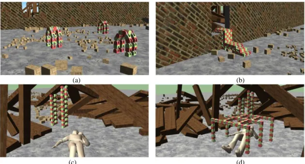
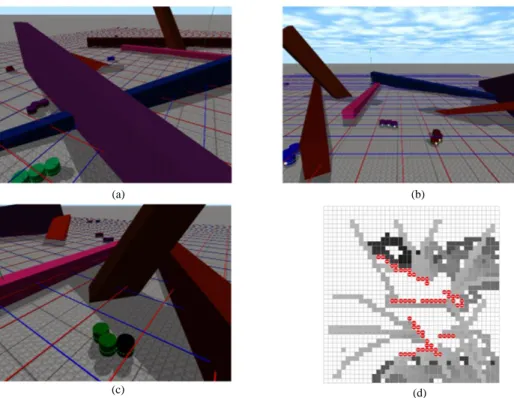
MRR has been studied in a number of areas, such as bionic, adaptive toolset, drug-delivery, inspection, rescue, exploration (satellite), mapping, and education and so on [17]. Figure II-1 gives an example of rescue application by M-TRAN [18]. M-TRAN can change its shape to achieve some tasks, such as locomotion in terrain through a four-legged gait, locomotion among debris through flow, supporting a beam, and to shelter survivors. Figure II-2 shows the Catoms [19] (in green, purple and blue). The Catoms collaboratively explore an unknown physical environment and inform a “macro” user through a data sink. Since groups of moving Catoms are able to share the map of the environment while transmitting it to the sink, a fast and detailed exploration of an unknown environment is facilitated [20].
(a) (b)
(c) (d)
Figure II-1 A rescue application by M-TRAN: (a) Locomotion in terrain through a four-legged Gait; (b) Locomotion among debris through flow; (c) Supporting a beam; (d) Shape formation to shelter survivors.
12
(a) (b)
(c) (d)
Figure II-2 Catoms scanning acomplex environment: (a) Snapshot of the environment (rear view); (b) Snapshot of the environment (front view); (c) Example of a Catom escaping a cavity trap with backtrack; (d) Map overview at tick 14940.
In the field of education, two MRRs have been successfully commercialized: Cellrobot [21] and Cubelets [22] (see Figure II-3).
Cellrobot. Cellrobot is a spherical shaped MSRR that consists of two kinds of modules, one called
“Heart” whose diameter is 88mm another one called “Cell” whose diameter is 80mm. Each module has eight joint faces which can be connected to each other through a simple twist movement. The joints will snap together for secure attachment. Cellrobot allows one Heart unit to be connected up to 20 Cells, including wheels and vision devices; each individual cell has a full 360-degree rotation. People can program and control Cellrobot through a smartphone.
Cubelets. Cubelets is a cubical shaped MSRR, which is designed for kids age 8 and up. Cubelets
modules connect to each other through permanent magnets, these modules can be divided into three categories based on their functions:
· Sense blocks, this type of module is equipped with sensors for temperature, light, etc.; · Think blocks, this type of module handles the information collected by the perceptual
modules, which determines how the robot responds;
13
Action modules receive instructions from the thinking modules and then respond. People also can program Cubelets via a computer.
(a)
(b)
Figure II-3 Two MRRs for education: Cellrobot (a), Cubelets (b)
II.2.2.MRRs from 1988 to 2017
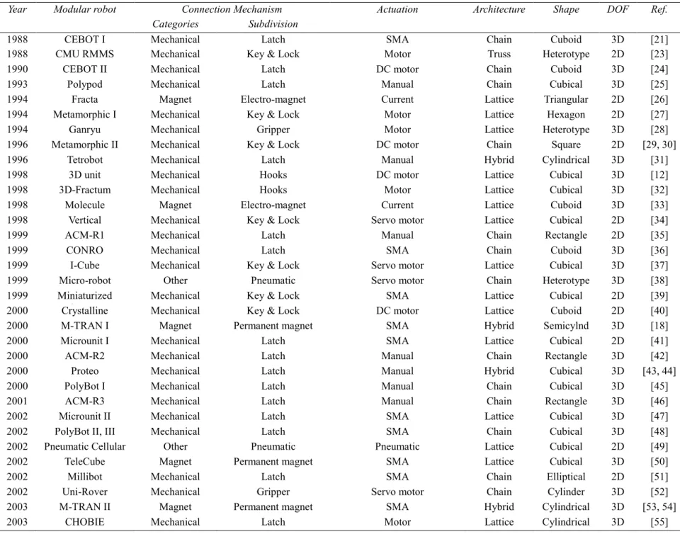
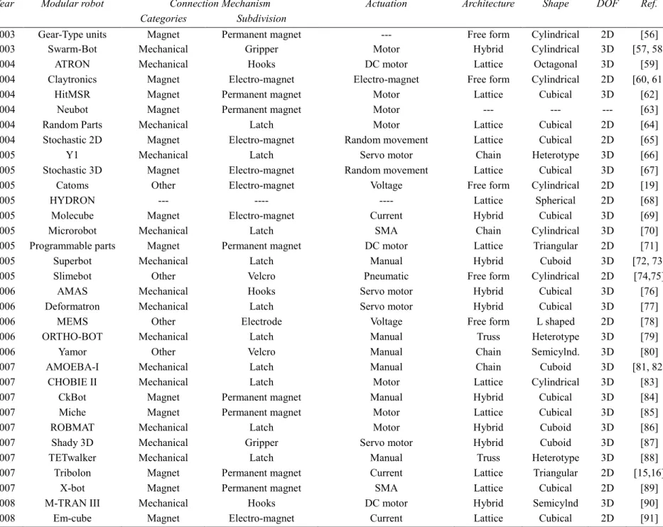
We present now MRR. We counted 121 types of MRRs. Table II-1 gives details on these MRRs, the information about connection mechanism, actuation mechanism, architecture, shape, and Degree Of Freedom (DOF) is also given here. Sometimes we present several versions of some MRRs when they had an important revolution.
14
Table II-1Modular robots characterized by their connection and actuation
Year Modular robot Connection Mechanism Actuation Architecture Shape DOF Ref.
Categories Subdivision
1988 CEBOT I Mechanical Latch SMA Chain Cuboid 3D [21]
1988 CMU RMMS Mechanical Key & Lock Motor Truss Heterotype 2D [23]
1990 CEBOT II Mechanical Latch DC motor Chain Cuboid 3D [24]
1993 Polypod Mechanical Latch Manual Chain Cubical 3D [25]
1994 Fracta Magnet Electro-magnet Current Lattice Triangular 2D [26]
1994 Metamorphic I Mechanical Key & Lock Motor Lattice Hexagon 2D [27]
1994 Ganryu Mechanical Gripper Motor Lattice Heterotype 3D [28]
1996 Metamorphic II Mechanical Key & Lock DC motor Chain Square 2D [29, 30]
1996 Tetrobot Mechanical Latch Manual Hybrid Cylindrical 3D [31]
1998 3D unit Mechanical Hooks DC motor Lattice Cubical 3D [12]
1998 3D-Fractum Mechanical Hooks Motor Lattice Cubical 3D [32]
1998 Molecule Magnet Electro-magnet Current Lattice Cuboid 3D [33]
1998 Vertical Mechanical Key & Lock Servo motor Lattice Cubical 2D [34]
1999 ACM-R1 Mechanical Latch Manual Chain Rectangle 2D [35]
1999 CONRO Mechanical Latch SMA Chain Cuboid 3D [36]
1999 I-Cube Mechanical Key & Lock Servo motor Lattice Cubical 3D [37]
1999 Micro-robot Other Pneumatic Servo motor Chain Heterotype 3D [38]
1999 Miniaturized
System Mechanical Key & Lock SMA Lattice Cubical 2D [39]
2000 Crystalline Mechanical Key & Lock DC motor Lattice Cuboid 2D [40]
2000 M-TRAN I Magnet Permanent magnet SMA Hybrid Semicylnd 3D [18]
2000 Microunit I Mechanical Latch SMA Lattice Cubical 2D [41]
2000 ACM-R2 Mechanical Latch Manual Chain Rectangle 3D [42]
2000 Proteo Mechanical Latch Manual Hybrid Cubical 3D [43, 44]
2000 PolyBot I Mechanical Latch Manual Chain Cubical 3D [45]
2001 ACM-R3 Mechanical Latch Manual Chain Rectangle 3D [46]
2002 Microunit II Mechanical Latch SMA Lattice Cubical 3D [47]
2002 PolyBot II, III Mechanical Latch SMA Chain Cubical 3D [48]
2002 Pneumatic Cellular Other Pneumatic Pneumatic Lattice Cubical 2D [49]
2002 TeleCube Magnet Permanent magnet SMA Lattice Cubical 3D [50]
2002 Millibot Mechanical Latch SMA Chain Elliptical 2D [51]
2002 Uni-Rover Mechanical Gripper Servo motor Chain Cylinder
arm 3D [52]
2003 M-TRAN II Magnet Permanent magnet SMA Hybrid Cylindrical 3D [53, 54]
15 Table II-1 Continue
Year Modular robot Connection Mechanism Actuation Architecture Shape DOF Ref.
Categories Subdivision
2003 Gear-Type units Magnet Permanent magnet --- Free form Cylindrical 2D [56]
2003 Swarm-Bot Mechanical Gripper Motor Hybrid Cylindrical 3D [57, 58]
2004 ATRON Mechanical Hooks DC motor Lattice Octagonal 3D [59]
2004 Claytronics Magnet Electro-magnet Electro-magnet Free form Cylindrical 2D [60, 61]
2004 HitMSR Magnet Permanent magnet Motor Lattice Cubical 3D [62]
2004 Neubot Magnet Permanent magnet Motor --- --- --- [63]
2004 Random Parts Mechanical Latch Motor Lattice Cubical 2D [64]
2004 Stochastic 2D Magnet Electro-magnet Random movement Lattice Cubical 2D [65]
2005 Y1 Mechanical Latch Servo motor Chain Heterotype 3D [66]
2005 Stochastic 3D Magnet Electro-magnet Random movement Lattice Cubical 3D [67]
2005 Catoms Other Electro-magnet Voltage Free form Cylindrical 2D [19]
2005 HYDRON --- ---- ---- Lattice Spherical 2D [68]
2005 Molecube Magnet Electro-magnet Current Hybrid Cubical 3D [69]
2005 Microrobot Mechanical Latch SMA Chain Cylindrical 3D [70]
2005 Programmable parts Magnet Permanent magnet DC motor Lattice Triangular 2D [71]
2005 Superbot Mechanical Latch Manual Hybrid Cuboid 3D [72, 73]
2005 Slimebot Other Velcro Pneumatic Free form Cylindrical 2D [74,75]
2006 AMAS Mechanical Hooks Servo motor Hybrid Cubical 3D [76]
2006 Deformatron Mechanical Latch Servo motor Hybrid Cubical 3D [77]
2006 MEMS Other Electrode Voltage Free form L shaped 2D [78]
2006 ORTHO-BOT Mechanical Latch Manual Truss Heterotype 3D [79]
2006 Yamor Other Velcro Manual Chain Semicylnd. 3D [80]
2007 AMOEBA-I Mechanical Latch Manual Chain Cuboid 3D [81, 82]
2007 CHOBIE II Mechanical Latch Motor Lattice Cylindrical 3D [83]
2007 CkBot Magnet Permanent magnet Manual Hybrid Cubical 3D [84]
2007 Miche Magnet Permanent magnet Motor Lattice Cubical 3D [85]
2007 ROBMAT Mechanical Latch Motor Hybrid Cuboid 3D [86]
2007 Shady 3D Mechanical Gripper Servo motor Hybrid Cuboid 3D [87]
2007 TETwalker Mechanical Latch Manual Truss Heterotype 3D [88]
2007 Tribolon Magnet Permanent magnet Current Lattice Triangular 2D [15,16]
2007 X-bot Magnet Permanent magnet SMA Lattice Cubical 2D [89]
2008 M-TRAN III Mechanical Hooks DC motor Hybrid Semicylnd 3D [90]
16 Table II-1 Continue
Year Modular robot Connection Mechanism Actuation Architecture Shape DOF Ref.
Categories Subdivision
2008 JL-1 Mechanical Latch DC motor Chain Trapezoid 3D [92]
2008 GZ-I Mechanical Latch Manual Chain Cubical 3D [93]
2008 Morpho Mechanical Latch Manual Truss Cubical 3D [94]
2008 Odin Mechanical Latch Manual Truss Cylindrical 3D [95]
2008 SYMBRION Mechanical Latch Motor Hybrid Cylindrical 3D [96]
2009 Hinge Mechanical Threads Manual Truss Cylindrical 3D [97]
2009 Raupi Mechanical Gripper Servo motor Hybrid Cylindrical 3D [98]
2009 Roombots Mechanical Hooks Manual Hybrid Cuboidal 3D [99]
2010 Factory Floor Mechanical Gripper Manual Truss Cylindrical 3D [100]
2010 JL-2 Mechanical Gripper DC motor Chain Trapezoid 3D [101]
2010 iMobot Mechanical Latch Manual Hybrid Cuboid 3D [102]
2010 Modular-Expanding Mechanical Threads Manual Chain Cylindrical 3D [103]
2010 Mod-Leg Mechanical Latch Servo motor Chain Cylindrical 3D [104]
2010 Responsive Truss Mechanical Key & Lock Manual Truss Cylindrical 3D [105]
2010 Sambot Mechanical Hooks Servo motor Lattice Cubical 3D [106]
2010 Single-material Mechanical Latch Random movement Lattice Cubical 3D [107] 2010 Pebbles Magnet Electro-permanent
magnet Random movement Lattice Cubical 2D [14]
2010 Stochastic fluidic Other Binder material Manual Lattice Cubical 3D [108]
2010 M3 Mechanical Hooks DC motor Hybrid L shaped 3D [109]
2010 Thor Mechanical Gripper DC motor Chain Cuboid 3D [110]
2010 UBot Mechanical Hooks DC motor Hybrid Cubical 3D [111]
2010 Vaccubes Other Pneumatic Manual Hybrid Cubical 3D [112]
2011 Steering Mechanical Latch --- Chain Cuboid 2D [113]
2011 Blinky blocks Magnet Permanent magnet Manual Lattice Cubical 3D [114]
2011 Anibot Mechanical Latch Heat Chian Cuboid 2D [115]
2011 Cross-ball Magnet Electro-magnet Motor Lattice Spherical 3D [116]
2011 Cubelets Magnet Permanent magnet Manual Lattice Cubical 3D [22]
2011 Heterogeneous
modules Mechanical Latch Motor Chain Cubical 3D [117]
2011 HitMSR II Mechanical Hooks Servo motor Chain Cubical 3D [118]
2011 M-Cubes Mechanical Latch DC motor Lattice Cubical 3D [119]
2011 M-Lattice Mechanical Latch Servo motor Lattice Triangular 2D [120]
2011 HexBot Magnet Electro-magnet DC motor Lattice Hexagonal 3D [121]
17 Table II-1 Continue
Year Modular robot Connection Mechanism Actuation Architecture Shape DOF Ref.
Categories Subdivision
2011 X-Cell Magnet Electro-magnet Motor Lattice Cubical 2D [123]
2012 ModRED Mechanical Latch Motor Chain Cuboid 3D [13]
2012 M3Express Mechanical Latch SMA & servo Hybrid L shaped 3D [124]
2012 Neurobot Mechanical Latch DC motor Hybrid Cubical 3D [125]
2012 Smart Blocks Magnet Electro-permanent magnet
Electro-permanent magnet Lattice Cubical 3D [5,6]
2012 SMORES Magnet Permanent magnet DC motor Hybrid Cubical 3D [126]
2012 Transmote Mechanical Key & Lock Manual Chain Cubical 3D [127]
2013 M-blocks 2D Magnet Permanent magnet Electro-permanent magnet Lattice Cubical 2D [128]
2013 USS Mechanical Latch Servo motor Chain Cubical 3D [129]
2013 Fable Magnet Permanent magnet Manual Chain Cylindrical 3D [130]
2014 Petro Mechanical Latch Manual Lattice Tetrahedral 3D [131]
2014 Cellrobot Mechanical Latch Manual Chain Spherical 3D [21]
2014 Soldercubes Other Binder material Current Hybrid Cubical 3D [132]
2015 M-blocks 3D Magnet Permanent magnet Electro-permanent magnet Lattice Cubical 3D [133]
2016 Trimobot Mechanical Hooks DC motor Hybrid Hexagonal 3D [134]
2016 HyMod Mechanical Latch Manual Lattice Cubical 3D [135]
2016 MHP Mechanical Latch Pump Lattice Cubical 3D [136]
2016 Diamobot Mechanical Latch Manual Hybrid Cubical 3D [137]
2016 Larva-Bot Mechanical Hooks Servo motor Lattice Cubical 3D [138]
2016 Pitch-pitch Mechanical Hooks Servo motor Chain Cubical 3D [139]
2017 EMeRGE Magnet Permanent magnet Manual Lattice Cubical 2D [140]
18
II.3. Classification and State of the Art
MRR can be classified into various categories and subcategories, among which the widely accepted classifications are based on architecture, scale, locomotion, and structure. The categories based on architecture are the primary and best-known classifications. Murata and Kurokawa [8] studied the architecture of modular robots and formally classified their architecture into the chain, lattice, hybrid, and truss. Some examples of these architectures are shown in Figure II-4, which could give people an intuitive vision. Then, Gilpin and Rus [142] introduced free-form architecture in order to cover a few unique systems that do not fit into conventional architectures.
(a) (b)
(c) (d) (e)
Figure II-4Some examples of modular robot architectures: (a) iMobot (hybrid) [102], (b) ATRON (lattice) [59], (c) YaMoR (chain) [80], (d) Odin (truss) [95], (e) Gear-Type Units (free-form) [56]
19
there is no cross, no corner in the structure when modules connect to each other. This structure is mainly used in some snake-shaped or warm-shaped modular robots, such as ACM [35]. The plane structure is a kind of modular robots that can only move in the plane, such as Fracta [26]. Spatial structure means that the modular robots can move in three-dimensions, such as Tetrobot [31], TeleCube [50], M-TRAN [18] and SuperBot [72, 73].
On what concerns aspects related to composition, actuation and connection are two main systems of a MRR. Therefore, we classified the MRR according to these two properties, as shown in Figure II-5. Details will be given in the following two sub-sections.
Figure II-5 Several classifications of MRRs
II.3.1. Classification via actuation mechanism
20
embedded in modules to enable gait locomotion, self-reconfiguration, self-assembly. Typically, actuators occupy more than 50% of the volume and weight of modules. We also note that actuation systems constitute major obstacles in downsizing modules [89].
When classifying MSRR based on actuation, we introduce the following classes: motor, manual and others (see Figure II-5). We detail now the different classes.
Motor
From the invention of modular robots to the present, the motor has been the most widely used actuation system. Furthermore, motor can also be subcategorized into brushless direct current (BLDC) motor like Telecube [50], PolyBot [45, 48], and Odin [95], brushed DC (BDC) motors like SMART [122], M3Express [124], and Roombots [99], stepper DC (SDC) motors like X-Cell [123] and ModRed [13], servo motor like CKBot [84].
Manual
In order to reduce the complexity of the controller and docking interfaces, some modular robots are sometimes assembled manually from an ensemble of different modules and connectors. They require human intervention at the time when reshaping of the morphology is desired. Since such kind of modular robots does not have to consider a complex actuation process, they are mainly designed to work with fixed topologies rather than for self-reconfiguration.
We stress that, even if this kind of modular robots is assembled manually, then they still may have the moving possibilities, GZ-I [93] is one example of modular chain robots with a manual configuration that can also achieve movement by cooperation.
Others
In addition to the motor and manual, with the development of materials science, sensor technology, there have been some interesting ways of actuation. Such as Shape Memory Alloy (SMA), pump, current, random movement, voltage and electro-permanent magnet.
II.3.2.Classification via connection mechanism
21
modules. Based on Connection mechanism, MRR can be categorized into mechanical, magnet, others (see Figure II-5).
Mechanical
Mechanical can be subcategorized into the latch, gripper, key & lock, hooks, and treads (examples are shown in Figure II-6). These methods have a big advantage of stability and can provide strong connecting force; but they also have some drawbacks, such as the complexity of structure and response time is relatively long. These drawbacks limit their application in robots, especially at a small scale.
Magnet
Magnet connection methods contain the permanent magnet (Miche [85]), electro-magnet (Hexbot [121]), and Electro-Permanent (EP) magnet (Pebbles [14]). Permanent magnets can provide a tight connection between modules, but they require manual intervention which is contrary to the idea of autonomous robots. Electro-magnet is easy to control and act fast; however, the limit is that it requires a continuous power supply. EP magnet can also act fast and does not need continuous power supply during working, which is a new concept of connector for modular robots.
Others
Mechanical and magnet can be seen as the traditional connection methods. Some new methods have been used in recent years. In Stochastic Fluidic Robot system, Tolley et al. present a novel reversible module connection mechanism using a low melting point alloy which is soldered to a fluid environment [107]. Meanwhile, other methods such as Velcro (Simebot [74]), binder material (Soldecubes [132]),
random movement (single-material [107]), pneumatic (Vaccubes [112]), electrodes (MEMS [78], where
MEMS is here the name of a robot) have also been used in MRR. We summaries them into others due to the limited applications.
22 (a) (b) (c) (d) (e)
Figure II-6 Mechanical connections (shown in the left of each subfigure) and their real applications (shown in the right of each subfigure): (a) HexaMob(latch) [141], (b)SWARM-BOT (gripper), (c) Transmote (key&lock), (d) Trimobot
(hooks), (e) Hinge (threads)
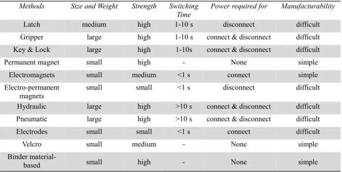
A qualitative comparison of several main connection methods for MRR can be seen in Table II-2. This table can provide a reference for choosing the connection method.
23
Table II-2Qualitative comparison of several connection methods for MRRs Methods Size and Weight Strength Switching
Time Power required for Manufacturability
Latch medium high 1-10 s disconnect difficult
Gripper large high 1-10 s connect & disconnect difficult Key & Lock large high 1-10s connect & disconnect difficult
Permanent magnet small high - None simple
Electromagnets small medium <1 s connect simple
Electro-permanent
magnets small small <1 s disconnect difficult
Hydraulic large high >10 s connect & disconnect difficult Pneumatic large high >10 s connect & disconnect difficult
Electrodes small small <1 s connect difficult
Velcro small medium - None simple
Binder
material-based small high - None simple
Through the analysis of Table II-1, we get the trend of the development of connection methods from the year 1988 to 2017 (see also Figure II-7). Obviously, mechanical is the most widely used connection method, the ratio of magnet systems is increasing.
Figure II-7 Trend of the connection methods
0 2 4 6 8 10 12 14 1988 1990 1993 1994 1996 1998 1999 2000 2001 2002 2003 2004 2005 2006 2007 2008 2009 2010 2011 2012 2013 2014 2015 2016 2017 N u m b er o f M o d u larro b o ts Year
24
II.4. Methods for Miniaturization
At present, most MRRs are in the research stage; they are rarely used in practical applications. One of the grand challenges of self-reconfiguring modular robotics is the assembly of a functional system from tens or hundreds of components. However, only systems comprised of small numbers of modules have been demonstrated. Miniaturization is one of the main reasons that stop MRR to be actually applied. One approach to scaling to large numbers of modules is to simplify module design by relieving the modules of the typical power, control, and actuation requirements necessary for locomotion like fluidic manipulation [107]. Scientists have made many attempts on this aspect. Therefore, some interesting design appears. There are three main methods for miniaturization.
II.4.1.Method 1: modules without actuation system
Since actuators occupy more than 50% of the volume and weight of modules, people developed some MRRs without actuation system. These MRRs are mainly used to study the communication between modules or control algorithms.
Miche. The Miche robots [85] (see Figure II-8 a) were invented by Kyle Gilpin, Keith Kotay, Daniela
Rus at MIT. Miche robots are a set of robots that consists of 28 1.8-inch autonomous cube-shaped robots which are able to connect to and communicate with their immediate neighbors. Modules can disengage their magnetic couplings and fall away under the influence of gravity. Miche robots starting from an amorphous arrangement can be assembled into arbitrary shapes and then commanded to self-disassemble in an organized manner to form complex 3D shapes. When assembled into a structure, the modules form a system that can be virtually sculpted using a computer interface via a distributed process.
In addition to gravity, random movements are also often used for modular combinations as in the following examples:
Pebbles. The Pebbles [14] (see Figure II-8 b) is also developed by Kyle Gilpin and Daniela Rus’s team
at MIT. With the assistance of external stochastic force which comes from a vibration table, Pebbles is capable of self-assembling into a uniform structure from a loose collection of disjoint modules. During the random movement, once a module meets with another one as desired, they will connect to each other
25
via electro-permanent magnets. Pebbles system forms an initial uniform grid of modules, and then subtracts the unnecessary modules until the goal structure is obtained.
material. Michael T. Tolley and Hod Lipson at Cornell University [107] developed the
Single-material system; it is composed of 15 mm scaled cubic modules which are made by 3D printing Single-material. Single-material can assemble 3D target structures stochastically within a 1.3 litter assembly tank by manipulating the fluid flow at an active assembly substrate using external valving. The modules connect to each other by a mechanical structure and do not have any electronic equipment or power supply (see Figure II-8 c).
Stochastic 2D and 3D. P.J. White et al. also from Cornell University [65, 67] presented several
modular robot systems in both 2D and 3D, all these robot systems do not have actuation system. The 2D system (see Figure II-8 d) has two prototype units, a square-shaped unit which uses electromagnets for connection and a triangle-shaped unit which use swivelling permanent magnets instead. The modules were shuffled randomly on an oscillating air table, when two modules collide properly, they bond one to another via the magnets, and release from each other if the configuration is not desired. The 3D system (see Figure II-8 e) uses electromagnets for connection, like Single-material robot, Stochastic 3D also moves thanks to the random fluid.
For the above modular robot systems, there are obvious drawbacks, they take time to reach the desired configuration, and they have a low success rate for configuration.
26
(a) (b) (c)
(d) (e)
Figure II-8 Some MRRs without actuation system: (a) Miche, (b) Pebbles, (c) Single-material, (d) Two prototype of Stochastic 2D units, (e) Stochastic 3D
II.4.2. Method 2: substitution of the actuation system for an affiliate system
Automatic Modular Assembly System (AMAS). Yuzuru Terada and Satoshi Murata at Tokyo
Institute of Technology [76, 143] developed AMAS to simplify construction work by introducing modularity into both structural components and means of assembly. AMAS is mainly composed of cubical modules; the modules can connect to each other by mechanical hooks on their surface. The AMAS modules do not contain actuation system. Thus, an affiliated system whose name is assembler robot was introduced (see Figure II-9). The assembler robot with four degrees of freedom can walk on the modules by using an inchworm motion, repeating connection and disconnection actions. The assembler robot can carry a module with its hand (L shaped part). Thus, the assembler robot can construct nearly any structure by combining basic assembly actions.
27
(a) Assembler robot
(b) Rotation (c) Inchworm motion Figure II-9 Automatic Modular Assembly System
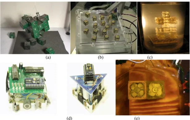
II.4.3. Method 3: multi-system multiplexing
Catoms. Catoms robot [19] provides a good idea about miniaturization of robots. Catoms belong
to Claytronics project carried out by Goldstein et al. at Carnegie Mellon University. Catoms is a series of cylindrical-shaped modular robots which had eight versions; the Planar Catom V8 is the newest one. The architecture of Catoms is free-form. The novel feature of Catoms is their ability to reconfigure (move) relative to one another without classical actuation methods presented in subsection II.3.1. Electromagnets are arranged around the robots, by controlling the state of electromagnets, a module can move and connect to other modules. Thus, one system can achieve both actuation and connection (see Figure II-10). This method is innovative; it can save size and weight. The drawbacks of Catoms are: the electro-magnets need a continuous power supply, and their cylindrical structure makes the movement tricky.
28
Figure II-10 Two prototypes of Catoms modular robot system
II.5. Distributed Algorithms and Simulators for MSRR
In this subsection, we deal with the different aspects related to control, distributed algorithm, software, and simulator of the reconfigurable modular robot. The reassembly process of MSRR has proven to be difficult to control because it involves the control of a distributed system with many mechanically coupled modules connected in time-varying ways [144]. Thus, a variety of distributed algorithms for MSRR has been developed.
In order to facilitate the task of programming ATRON, U. P. Schultz [145] presented a concept of distributed control diffusion: distributed queries are used to identify modules that play a specific role in the robot, and behaviours that implement specific control strategies are diffused throughout the robot based on these role assignments. Kamimura et al. developed both centralized and decentralized control method for M-TRANN III [90]. W M Shen et al. have presented a biologically inspired approach to distributed collaboration between the physically coupled modules for CONRO. This approach was used to accomplish global effects such as locomotion and reconfiguration [146]. Miao et al. [147] proposed a distributed algorithm for enveloping an object inside a hexagonal lattice environment based on local communications among neighboring modules and between modules and the lattice node containing a target object.
Julien Bourgeois’s team contributed a lot on distributed self-reconfiguration algorithm for cylindrical modular robots, such as Catoms. In 2014, they proposed a flexible distributed algorithm allowing the reorganization of a set of modular micro-robots into the desired target shape. Since their algorithm does not need an explicit description of the final shape, it shows a great flexibility concerning the range of target shapes [148]. In 2016, they proposed a parallel, asynchronous and fully decentralized
29
distributed algorithm to self-reconfigure robots from an initial configuration to a goal one. They also evaluated their algorithm at the millimetre-scale, which indicates that the number of communications, the number of movements and the execution time of their algorithm is highly predictable [149].
El Baz at LAAS-CNRS developed a distributed algorithm based on distributed election for establishing quickly a smart conveyor made of smart modules. This research work was done in the framework of the ANR Smart Block project [6].
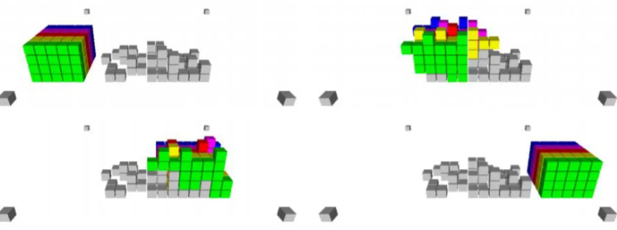
Robert Fitch et al. present both centralized and decentralized algorithms for cubical MSRR, which plans module trajectories through the volume of the structure. They define free space by an arbitrarily-shaped bounding region. This addresses the important problem of reconfiguration among obstacles, and reconfiguration over a rigid surface [150]. By using this algorithm, they successfully simulated a transformation from a chair to a table (see Figure II-11).
Figure II-11 Example of simulation of reconfiguration for cubical MSRR
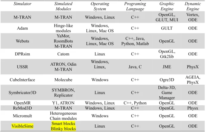
Meanwhile, many simulators for MRRs have been developed, such as Adam [151], Webots [152], OpenMR [153] (see Table II-3). These simulators allow people to create virtual environments for MRR, such as robots work on the surface of water [154], under the water [155] or on an air surface [156]. Simulators also allow people to visualize and debug in real-time, for example, VisibleSim permits one to test and visualize distributed algorithms in a 3D environment. As a consequence, simulators can not only facilitate the development of efficient algorithms but also can inspire hardware designers with innovative features [17].
![Figure II-6 Mechanical connections (shown in the left of each subfigure) and their real applications (shown in the right of each subfigure): (a) HexaMob (latch) [141], (b) SWARM-BOT (gripper), (c) Transmote (key&lock), (d) Trimobot](https://thumb-eu.123doks.com/thumbv2/123doknet/14526145.723006/39.918.204.735.104.897/mechanical-connections-subfigure-applications-subfigure-hexamob-transmote-trimobot.webp)