HAL Id: tel-02076289
https://tel.archives-ouvertes.fr/tel-02076289
Submitted on 22 Mar 2019HAL is a multi-disciplinary open access archive for the deposit and dissemination of sci-entific research documents, whether they are pub-lished or not. The documents may come from teaching and research institutions in France or abroad, or from public or private research centers.
L’archive ouverte pluridisciplinaire HAL, est destinée au dépôt et à la diffusion de documents scientifiques de niveau recherche, publiés ou non, émanant des établissements d’enseignement et de recherche français ou étrangers, des laboratoires publics ou privés.
fretting : applications au contact tige/col dans les
prothèses de hanches modulaires
Haohao Ding
To cite this version:
Haohao Ding. Tribologie du Ti-6AI-4V et d’un revêtement DLC en fretting : applications au contact tige/col dans les prothèses de hanches modulaires. Autre. Université de Lyon, 2018. Français. �NNT : 2018LYSEC029�. �tel-02076289�
N°d’ordre NNT : 2018LYSEC029
THESE de DOCTORAT DE L’UNIVERSITE DE LYON
opérée au sein de l’Ecole centrale de Lyon
Ecole Doctorale N° 34
Ecole Doctorale des Matériaux de Lyon
Spécialité de doctorat :
Matériaux
Soutenue le 24 octobre 2018, par :
Haohao DING
TRIBOLOGY OF Ti–6Al–4V AND DLC COATING IN FRETTING:
APPLICATIONS TO STEM / NECK CONTACT OF MODULAR HIP IMPLANT
TRIBOLOGIE DU Ti–6Al–4V ET D'UN REVETEMENT DLC EN FRETTING :
APPLICATIONS AU CONTACT TIGE / COL DANS LES PROTHESES
DE HANCHES MODULAIRES
Devant le jury composé de :
Donnet, Christophe Professeur, Université Jean Monnet Président de jury Langlade, Cécile Professeur, UTBM Rapporteure Denape, Jean Professeur, ENI Tarbes Rapporteur Carpentier, Luc Maître de conférences, UBFC Examinateur Sfarghiu, Ana-Maria Chargée de recherche CNRS, INSA de Lyon Examinatrice Kapsa, Philippe Directeur de recherche émérite au CNRS, ECL Directeur de thèse Fridrici, Vincent Maître de conférences, ECL Co-directeur de thèse Fontaine, Julien Chargé de recherche CNRS, ECL Membre invité Géringer, Jean Maître-Assistant, Mines St-Etienne Membre invité
ACKNOWLEDGEMENTS
I express my sincere gratitude to Prof. Philippe KAPSA, my supervisor of the thesis, for giving me basics of research and supporting me during the whole thesis work.
I address my special appreciation to Dr. Vincent FRIDRICI, my co-supervisor of the thesis. During my three years of thesis, he gave me uncountable suggestions and professional guidance to my work. He also patiently and critically proofread the manuscript.
I would like to express my thanks to all the colleagues in the laboratory for their generous help. In particular, I would like to thank Dr. Marième FALL for her great help on my study and life in France. I would also like to present my thanks to Gaëtan BOUVARD and Thomas MALHOMME for training in testing and analytical machines and to Dr. Gaylord GUILLONNEAU and Dr. Julien FONTAINE for their valuable suggestions on my work.
I would like to acknowledge the support from LabEx MANUTECH-SISE and IREIS. I would also express my thanks to Dr. Jean GÉRINGER and Dr. Sergio SAO-JOAO from Ecole des Mines de Saint-Etienne for valuable suggestions on my work.
I am so grateful to Prof. Wenjian WANG and Prof. Qiyue LIU, for being my supervisors of master’s thesis at Southwest Jiaotong University in China. They brought me into the tribology world. I would also like to thank Prof. Minhao ZHU and Prof. Zhongrong ZHOU for recommending me to study in LTDS.
I would like to thank China Scholarship Council for its financial support.
At the end, I must appreciate my parents and sisters for their supporting on my overseas study.
Abstract
The use of modular neck adapter when placing a total hip prosthesis introduces a new interface, between the femoral stem and the neck adapter, which is propitious to fretting damage during walking. Ti–6Al–4V alloy has been widely used in neck adapters and femoral stems. However, the Ti–6Al–4V / Ti–6Al–4V contacts present high friction and severe adhesive wear under fretting conditions. Diamond-like carbon (DLC) coatings have been widely used as protective coatings for metallic parts. Thus, they can be introduced into Ti–6Al–4V neck adapter / Ti–6Al–4V femoral stem contacts.
The objective of this thesis is to investigate the tribological behaviors of DLC coating and Ti–6Al–4V alloy under fretting conditions for application to neck adapter / femoral stem contact. Fretting tests are conducted with a cylinder / flat contact under different values of displacement amplitude (±20 µm, ±40 µm, and ±70 µm) and normal force (between 200 N and 1 200 N). Furthermore, the effects of different DLC coatings (DLC A and DLC B), different surface roughness (smooth and rough), different coating positions (coating on the flat, on the cylinder, and on both surfaces), different environments (laboratory air and calf serum) are analyzed. Besides, the origin of low friction of Ti–6Al–4V / DLC coating contact is explored. The mechanical properties of tribofilm formed on the rubbed Ti–6Al–4V surface is studied.
For fretting tests without coating (Ti–6Al–4V / Ti–6Al–4V contact) under laboratory air condition, the friction coefficient is high, between 0.8 and 1.2. The wear volume increases with the displacement amplitude. For fretting tests with coating, Ti–6Al–4V can be well protected under relatively low load conditions. The friction coefficient is low (around 0.2) and the wear volume is small. Under high load conditions, the coating is almost totally removed. The friction and wear volume are similar to tests without coating. The harder coating (DLC A) has better tribological property than DLC B. The coating on the smooth surface exhibits better fretting performance than on the rough surface. Coating on a cylindrical surface shows better tribological performance than on a flat surface. The DLC coating is damaged more severely when it slides against a DLC coating than against the uncoated Ti–6Al–4V alloy. The coating performs better under the serum condition than under the laboratory air condition. A tribofilm is formed on the rubbed Ti–6Al–4V surface when sliding against a DLC coating under low load conditions. The tribofilm shows higher hardness, higher Young’s modulus, higher compression modulus, higher yield strength than the Ti–6Al–4V alloy. A tribological model is proposed for tribofilm formation and explanation of origin of low friction, by in-depth analysis of contact surfaces, on mechanical and chemical points of view.
Keywords: Fretting, friction, wear, Ti–6Al–4V, diamond-like carbon coating, surface roughness,
une nouvelle interface, entre la tige et le col, qui est susceptible de s’endommager par fretting lors de la marche. L’alliage Ti–6Al–4V est très largement utilisé pour les tiges et les cols. Cependant, les contacts Ti–6Al–4V / Ti–6Al–4V présentent un frottement élevé et une forte usure adhésive dans les conditions de fretting. Les revêtements DLC (diamond-like carbon) ont été largement utilisés comme revêtements protecteurs pour les pièces métalliques. Ainsi, ils peuvent être introduits dans les contacts entre la tige en Ti–6Al–4V et le col en Ti–6Al–4V. L’objectif de cette thèse est d’étudier les comportements tribologiques du revêtement DLC et de l’alliage Ti–6Al–4V dans les conditions de fretting pour application au contact entre la tige et le col. Les essais de fretting sont menés avec un contact cylindre sur plan sous différentes valeurs d’amplitude de déplacement (± 20 μm, ± 40 μm, et ± 70 μm) et de force normale (entre 200 N et 1 200 N). En outre, les effets de différents revêtements (DLC A et DLC B), différentes rugosités de surface (lisse et rugueuse), différentes positions de revêtement (revêtement sur le plan, sur le cylindre et sur les deux surfaces), différents environnements (dans l’air et dans le sérum de veau) sont analysés. Par ailleurs, l'origine du faible frottement du contact entre Ti–6Al–4V et revêtement DLC est explorée. Les propriétés mécaniques du tribofilm formé sur la surface de Ti–6Al–4V frottée sont également étudiées.
Pour les tests de fretting sans revêtement (contact Ti–6Al–4V / Ti–6Al–4V) dans l’air, le coefficient de frottement est élevé, entre 0.8 et 1.2. Le volume d’usure croît avec l’amplitude de déplacement. Pour les tests avec revêtement, le Ti–6Al–4V peut être bien protégé, sous des charges relativement faibles. Le coefficient de frottement (d’environ 0,2) et le volume usé sont faibles. Sous fortes charges, le revêtement est presque totalement éliminé. Le frottement et le volume d'usure sont similaires à ceux des essais sans revêtement. Le revêtement plus dur (DLC A) a de meilleures propriétés tribologiques que le DLC B. Le revêtement sur la surface lisse présente une meilleure performance en fretting que sur la surface rugueuse. Le revêtement sur une surface cylindrique présente une meilleure performance tribologique que sur une surface plane. Le revêtement DLC est plus endommagé lorsqu'il glisse contre un revêtement DLC que contre du Ti–6Al–4V non revêtu. Le revêtement fonctionne mieux en présence de sérum que dans l’air. Un tribofilm est formé sur la surface de Ti–6Al–4V frottée lorsqu'il glisse contre un revêtement DLC sous de faibles charges. Le tribofilm présente une dureté plus élevée, un module de Young plus élevé, un module de compression plus élevé, une limite d'élasticité plus élevé que l’alliage Ti–6Al–4V. Un modèle tribologique est proposé pour la formation du tribofilm et l'explication de l'origine du faible frottement, par une analyse approfondie des surfaces de contact, sur les points de vue mécaniques et chimiques.
Mot-clés : Fretting, frottement, usure, Ti–6Al–4V, revêtement diamond-like carbon, rugosité
i
CONTENTS
INTRODUCTION ... 1
CHAPTER I: BIBLIOGRAPHY SYNTHESIS ... 9
1. Introduction ... 9
2. Modular hip implant ... 10
2.1. Total hip replacement (THR) ... 10
2.2. Modular design of femoral stem ... 11
2.3. Materials for femoral stem ... 11
2.3.1. Stainless steels ... 12
2.3.2. Cobalt–chromium alloys ... 13
2.3.3. Titanium alloys ... 13
2.4. Tribological response of total hip implants ... 15
2.4.1. Load conditions at femoral stem / neck adapter contact interface ... 15
2.4.2. Fretting ... 16
2.4.3. Friction of metallic materials for implants ... 18
2.4.4. Wear of metallic materials for implants ... 19
2.4.5. Corrosion of metallic materials for implants ... 19
2.4.6. Fracture failure of modular hip implant components ... 20
3. Coatings for tribological applications ... 21
3.1. Type of coatings ... 21
3.1.1. Soft coatings ... 21
3.1.2. Hard coatings ... 22
3.2. Coating deposition methods ... 23
3.2.1. Bonding ... 23 3.2.2. IBD ... 23 3.2.3. PVD ... 23 3.2.4. CVD ... 25 4. DLC coatings ... 27 4.1. Structure of DLC ... 27 4.2. Types of DLC coatings ... 28
4.3. Growth mechanism of DLC coatings ... 29
4.3.1. Ion beam deposited ta–C ... 29
ii
4.4. Mechanical properties of DLC coating ... 32
4.4.1. Hardness and elasticity ... 32
4.4.2. Compressive stresses ... 34
4.4.3. Summary of mechanical properties of DLC coatings ... 35
4.5. Cohesion between DLC coatings and substrate ... 35
4.6. Biocompatibility of DLC coatings ... 35
4.6.1. In vitro and in vivo experiments ... 35
4.6.2. Clinical application ... 36
5. Tribological response of DLC coatings ... 37
5.1. Low friction ... 37
5.2. Structural and chemical changes of DLC surface during sliding ... 38
5.2.1 Passivation ... 38
5.2.2 Rehybridization ... 39
5.3. Transfer from DLC surface to the countersurface ... 40
5.4. Wear resistance ... 41
5.5. Improvement of DLC coating properties ... 42
5.5.1. Incorporation of elements... 42
5.5.2. Multilayer structure ... 44
6. Influence of different parameters on tribological behavior of contacts ... 46
6.1. Roughness ... 46
6.1.1. Metal / metal contact ... 46
6.1.2. Metal / coating contact ... 47
6.2. Coating position... 49
6.2.1. Influence of substrate curvature ... 49
6.2.2. Coating on both contact surfaces ... 49
6.3. Environment ... 49
7. Conclusions ... 50
CHAPTER II: EXPERIMENTAL METHODS AND MATERIALS UNDER INVESTIGATION ... 55
1. Introduction ... 55
2. Materials and surfaces ... 55
2.1. Ti–6Al–4V ... 55
2.1.1. Microstructure and chemical composition of Ti–6Al–4V ... 55
2.1.2. Surface roughness of Ti–6Al–4V samples ... 56
2.1.3. Mechanical properties of Ti–6Al–4V ... 58
iii
2.2.1. Deposition process and chemical compositions ... 58
2.2.2. Coating thickness and interlayer ... 59
2.2.3. Surface roughness of DLC coated samples ... 61
2.2.4. Mechanical properties of DLC coatings ... 63
2.3. Summary... 64 3. Fretting rig ... 64 4. Test conditions ... 65 5. Analysis methods ... 67 5.1. 2D contact profilometer ... 68 5.2. Optical interferometer ... 68 5.3. Digital microscope ... 68 5.4. SEM ... 68 5.5. Nano-indenter ... 69
5.6. Compression system of micro-pillar ... 69
6. Conclusions ... 70
CHAPTER III: EFFECT OF SURFACE ROUGHNESS ON FRETTING BEHAVIOR OF Ti–6Al–4V / Ti–6Al–4V CONTACT ... 75
1. Introduction ... 75
2. Tribological behaviors: presentation of results ... 75
2.1. RCFM ... 75
2.2. Friction coefficient ... 81
2.3. Wear volume ... 83
2.4. Wear scars ... 84
2.5. Tribologically transformed structure ... 85
2.6. Cracks on cross section ... 87
2.7. Wear debris ... 89
3. Analysis of effect of surface roughness on fretting behaviors ... 90
4. Conclusions ... 92
CHAPTER IV: INFLUENCE OF DIFFERENT PARAMETERS ON FRETTING BEHAVIOR OF DLC COATINGS ... 95
1. Introduction ... 95
2. Tribological behavior ... 96
2.1. Friction coefficient ... 96
iv
2.3. Wear scars ... 102
2.3.1. Mild wear area ... 102
2.3.2. Severe wear area ... 104
2.3.3. Wear scars on flat samples ... 106
2.4. Coating response wear maps ... 109
2.5. RCFM ... 111
2.6. Wear debris ... 115
2.7 Cracks inside DLC coating ... 118
2.8 Conclusions ... 120
3. Effect of parameters on fretting behavior ... 120
3.1. Comparison of different DLC coatings ... 120
3.2. Surface roughness ... 125
3.3. Coating positions ... 128
3.3.1. Coating on flat vs. coating on cylinder ... 128
3.3.2. Coating on one surface vs. coating on both surfaces ... 131
4. Proposition of coating failure process ... 132
5. Tribological model for coating response ... 133
6. Conclusions ... 135
CHAPTER V: EFFECT OF SERUM ON FRETTING BEHAVIOR OF Ti–6Al–4V AND DLC COATING ... 139
1. Introduction ... 139
2. Effect of serum on fretting behavior of Ti–6Al–4V / Ti–6Al–4V contact ... 140
2.1. RCFM ... 140 2.2. Friction coefficient ... 142 2.3. Wear volume ... 145 2.4. Wear scars ... 146 2.5. TTS ... 150 2.6. Cracks ... 151
2.7. Analysis of effect of serum liquid on fretting behavior of Ti–6Al–4V / Ti–6Al–4V contact ... 152
3. Effect of serum on fretting behavior of Ti–6Al–4V / DLC coating contact ... 153
3.1. Friction coefficient ... 153
3.2. Wear volume ... 156
3.3. Wear scars ... 158
3.4. Coating response wear map ... 160
3.5. Analysis of effect of serum liquid on fretting behavior of Ti–6Al–4V / DLC coating contact ... 161
v
CHAPTER VI: UNDERSTANDING LOW FRICTION OF DLC COATING UNDER LOW LOAD CONDITION
... 167
1. Introduction ... 167
2. Friction coefficient under different contact conditions ... 168
2.1. Rubbed DLC coating surface / rubbed Ti–6Al–4V surface contact ... 169
2.2. Rubbed DLC coating surface / new Ti–6Al–4V surface contact ... 170
2.3. New DLC coating surface / rubbed Ti–6Al–4V surface contact ... 171
2.4. Conclusions on running-in ... 171
3. Evolution of wear scars ... 171
3.1. Contact only (0 fretting cycle) ... 172
3.2. After 1 cycle ... 175
3.3. After 20 cycles (in running-in) ... 176
3.4. After 40 cycles (in running-in) ... 178
3.5. After 100 cycles (just after running-in)... 180
3.6. After 100 000 cycles ... 184
3.7. Conclusions ... 185
4. Properties of rubbed contact surfaces ... 187
4.1. Thickness of tribofilm ... 187
4.2. Raman spectroscopy on rubbed surfaces ... 188
4.3. Nano-indentation on tribofilm ... 192
4.4. Compression of micro pillar of tribofilm ... 193
4.5. Conclusions ... 201
5. Tribological model for tribofilm formation ... 202
6. Analysis of origin of low friction ... 204
7. Conclusions ... 206
GENERAL CONCLUSIONS AND PERSPECTIVES ... 209
REFERENCES ... 217
APPENDIX ... 231
Appendix A. Calculation of normal force corresponding to the real contact conditions ... 231
Appendix B. Calculation of wear volume ... 232
Appendix C. Correction of sample, punch, frame compliance for pillar compression... 233
1
INTRODUCTION
Background
Modular neck adapter has been introduced into total hip arthroplasty (THA) to facilitate the replacement surgery. However, it introduces a new interface, neck adapter / femoral stem (as shown in Figure Intro.1), which is under fretting condition during people walking. Furthermore, Ti–6Al–4V alloy has been widely used in neck adapters and femoral stems due to its high specific strength, corrosion resistance and biocompatibility. However, the Ti–6Al– 4V / Ti–6Al–4V contacts present high friction and severe adhesive wear under fretting conditions. Therefore, the anti-fretting properties of Ti–6Al–4V neck adapter / Ti–6Al–4V femoral stem contacts should be improved.
Figure Intro.1. Bi-modular femoral stem.
Diamond-like carbon (DLC) coatings can be used as protective coatings for metallic parts. They exhibit excellent tribological performance due to their low friction and high hardness, in many environments. Furthermore, DLC coatings show high biocompatibility, which makes them proper for implant applications.
In this thesis, DLC coatings are studied in order to analyze their possible application at the neck adapter / femoral stem (Ti–6Al–4V / Ti–6Al– 4V) contact to improve its tribological performance in fretting. The influences of surface roughness, coating position, and environment on the performance of DLC coatings and Ti–6Al–4V alloy are investigated. At last, the origin of low friction of DLC coating is discussed.
2
In this thesis, tribological performance of DLC coatings in fretting is studied in order to analyze the possible application of DLC at the neck adapter / femoral stem (Ti–6Al–4V / Ti– 6Al–4V) contact.
Objectives and research approaches
The objectives of this thesis are to investigate the fretting behavior of DLC coatings and Ti–6Al–4V alloy for neck adapter and femoral stem applications.
In order to reach these objectives, the following research approaches will be realized. At first, literature study will be carried out to investigate the development of THA, coatings for tribological applications, and the development of DLC coatings. Based on the literature study, DLC coatings are determined for neck adapter / femoral stem (Ti–6Al–4V / Ti–6Al–4V) applications. Then, fretting experiments will be performed to investigate the fretting behavior of DLC coating and Ti–6Al–4V alloy. Furthermore, the influence of different parameters, including surface roughness, coating position and serum environment, on the fretting behavior of DLC coatings and Ti–6Al–4V will be explored. Finally, the origin of low friction of DLC coating will be discussed.
Organization of the manuscript
The manuscript is organized as presented in Figure Intro.2.
In Chapter I, literature study will be summarized, including the development of modular hip implant, the coating types and deposition methods, the DLC coatings and their tribological response, and the influences of different parameters on tribological behavior of contacts.
Chapter II will introduce the materials under investigation, including the Ti–6Al–4V substrate and DLC coatings, the experimental and analytical methods, and the test conditions. In Chapter III, the fretting behavior of Ti–6Al–4V / Ti–6Al–4V contact will be investigated under laboratory air condition. The effect of surface roughness will be explored. The results will serve as baselines for the study of the effect of DLC coating in next chapters.
Chapter IV will investigate the fretting behavior of DLC coatings under laboratory air condition. The influence of different parameters will be explored, including different DLC coatings, different surface roughness, and different coating positions.
In Chapter V, the influence of serum on the fretting behavior of Ti–6Al–4V will be investigated with a Ti–6Al–4V / Ti–6Al–4V contact. The influence of serum on the tribological performance of a DLC coating will be investigated with a coating / Ti–6Al–4V contact.
Chapter VI investigates the origin of low friction for the DLC coating / Ti–6Al–4V contact under low load conditions. At last, a tribological model for the evolution of DLC coating / Ti– 6Al–4V contact under low load condition will be proposed.
3
Figure Intro.2. Organization of the manuscript.
Chapter I: Bibliography synthesis
- Modular hip implant;
- DLC coatings;
- Parameters influencing tribological behavior.
Chapter II: Experimental methods and materials under investigation
- Materials (Ti–6Al–4V and DLC coatings);
- Test rig and test conditions.
Chapter III: Effect of surface roughness on fretting behavior of Ti–6Al–4V / Ti–6Al–4V contact
Chapter IV: Influence of different parameters on fretting behavior of DLC coatings
- Comparison of different DLC coatings;
- Effect of surface roughness;
- Effect of coating positions.
Chapter V: Effect of serum on fretting behavior of Ti–6Al–4V and DLC coating
- Effect of serum on Ti–6Al–4V;
- Effect of serum on DLC coating.
Chapter VI: Understanding low friction of DLC coating under low load condition
- Detailed analyses of rubbed surfaces;
- Tribological model for evolution of DLC
coating / Ti–6Al–4V contact.
5
CHAPTER
I
6
CHAPTER I : BIBLIOGRAPHY SYNTHESIS
1. Introduction ... 9
2. Modular hip implant ... 10
2.1. Total hip replacement (THR) ... 10
2.2. Modular design of femoral stem ... 11
2.3. Materials for femoral stem ... 11
2.3.1. Stainless steels ... 12
2.3.2. Cobalt–chromium alloys ... 13
2.3.3. Titanium alloys ... 13
2.4. Tribological response of total hip implants ... 15
2.4.1. Load conditions at femoral stem / neck adapter contact interface ... 15
2.4.2. Fretting ... 16
2.4.3. Friction of metallic materials for implants ... 18
2.4.4. Wear of metallic materials for implants ... 19
2.4.5. Corrosion of metallic materials for implants ... 19
2.4.6. Fracture failure of modular hip implant components ... 20
3. Coatings for tribological applications ... 21
3.1. Type of coatings ... 21
3.1.1. Soft coatings ... 21
3.1.2. Hard coatings ... 22
3.2. Coating deposition methods ... 23
3.2.1. Bonding ... 23 3.2.2. IBD ... 23 3.2.3. PVD ... 23 3.2.4. CVD ... 25 4. DLC coatings ... 27 4.1. Structure of DLC ... 27 4.2. Types of DLC coatings ... 28
4.3. Growth mechanism of DLC coatings ... 29
4.3.1. Ion beam deposited ta–C ... 29
4.3.2. Plasma deposited a–C:H ... 31
4.4. Mechanical properties of DLC coating ... 32
4.4.1. Hardness and elasticity ... 32
7
4.4.3. Summary of mechanical properties of DLC coatings ... 35
4.5. Cohesion between DLC coatings and substrate ... 35
4.6. Biocompatibility of DLC coatings ... 35
4.6.1. In vitro and in vivo experiments ... 35
4.6.2. Clinical application ... 36
5. Tribological response of DLC coatings ... 37
5.1. Low friction ... 37
5.2. Structural and chemical changes of DLC surface during sliding ... 38
5.2.1 Passivation ... 38
5.2.2 Rehybridization ... 39
5.3. Transfer from DLC surface to the countersurface ... 40
5.4. Wear resistance ... 41
5.5. Improvement of DLC coating properties ... 42
5.5.1. Incorporation of elements... 42
5.5.2. Multilayer structure ... 44
6. Influence of different parameters on tribological behavior of contacts ... 46
6.1. Roughness ... 46
6.1.1. Metal / metal contact ... 46
6.1.2. Metal / coating contact ... 47
6.2. Coating position... 49
6.2.1. Influence of substrate curvature ... 49
6.2.2. Coating on both contact surfaces ... 49
6.3. Environment ... 49
9
CHAPTER I: BIBLIOGRAPHY SYNTHESIS
1. Introduction
In the year of 1962, Doctor John Charnley developed low-friction arthroplasty of the hip at Wrightington Hospital. Since then, total hip replacement (THR) has become a popular surgery to restore the hip function [1]. More than 500 000 THRs are done every year in the UK and USA, with excellent clinical outcomes showing greater than 95% survivorship at 10-year follow-up, and greater than 80% implant survivorship at 25-year follow-up [2].
Since 1990s, modular neck adapters have been introduced into THRs to fit different individuals by using different neck adapters with different shapes (i.e. neck adapter length, neck–stem angles, etc.) and thus to facilitate the replacement surgery [3]. However, the use of neck adapters introduces a new interface, neck adapter–femoral stem interface, which is under fretting conditions, i.e. cyclic loading and relative micromotions, during walking [4].
Ti–6Al–4V has been widely used in hip implants owing to its high specific strength, corrosion resistance and biocompatibility. However, Ti–6Al–4V / Ti–6Al–4V contacts present poor tribological performance including high friction coefficients and severe adhesive wear under fretting conditions [5].
Diamond-like carbon (DLC) coatings, which offer the combination of high hardness and low friction in many environments, can improve the tribological performance of the metallic substrates [6]. DLC coatings are used in many applications including bearings, gears, cams, valves, forming tools, computer hard discs, etc. Furthermore, DLC coatings have excellent corrosion resistance and biocompatibility, which enable them to be used in hip prosthesis applications [6].
The objective of this thesis is to study the influence of DLC coatings on the fretting behaviors of Ti–6Al–4V alloy for neck adapter–femoral stem contact in modular hip implant applications.
In this chapter, literature study is summarized to understand the research context, including the modular hip implant, coating types, coating deposition methods, diamond-like carbon coatings and their mechanical and tribological properties, and some parameters influencing tribological behavior of contacts.
10
In this Chapter, literature study will be summarized, including the development of modular hip implant, the coating types and deposition methods, the DLC coatings and their tribological response, and the influences of different parameters on tribological behavior of contacts.
2. Modular hip implant
2.1. Total hip replacement (THR)
THR is amongst the most common and successful surgical procedures performed today, and aims to restore function and relieve pain by replacing the articulating surfaces of the joints and can result in significant improvements in patient’s quality of life [7–9]. THR has become popular since John Charnley developed the low friction arthroplasty over 50 years ago using a metal ball articulating with a Teflon® cup and subsequently (with significantly greater success) a polyethylene cup [10, 11]. In England and Wales, almost 65 000 and over 71 000 THRs were performed during 2008 and 2011, respectively, and 93% of them were performed for osteoarthritis [7–9].
The components in a total hip replacement consist of an acetabular cup, a femoral head, and a femoral stem. The femoral head articulates with the acetabular cup or a liner placed within the cup. The head may be made from stainless steel, cobalt-chromium or ceramic. The acetabular component may be made of polyethylene or metal, or be metal backed using a polyethylene or ceramic liner. The metal-on-polyethylene bearing is the most frequently used [7], as shown in Figure I.1.
Figure I.1. Total hip replacement with a metal-on-polyethylene contact [12].
Fixation of THRs to patients may be cemented, uncemented, or hybrid (e.g., the stem is cemented and the cup is uncemented) [7, 9, 13]. Cemented implants are placed into a bed of polymethyl methacrylate (PMMA) bone cement which ensures the components into the prepared acetabulum and femoral canal. Uncemented implants have either a porous coating into which bone can grow or a roughened surface, produced by blasting the surface of the
11 implant with microscopic particles, to increase surface area for bone to grow onto [7]. Long-term outcomes for cemented and uncemented techniques demonstrate no clear difference [9]. There is an increasing tendency to use uncemented implants in younger patients because of the potential for a permanent bone-implant interface [7].
2.2. Modular design of femoral stem
A conventional monoblock femoral stem is made of a single piece, as shown in Figure I.1. Studies have demonstrated that a monoblock stem has a limited capacity to accurately restore the hip center of rotation and femoral offset in a significant proportion of patients [14]. Femoral offset is the distance from the center of rotation of the femoral head to a line dissecting the long axis of the femur. In case of THR, the offset is considered as the distance from the center of rotation of the femoral head to a line dissecting the long axis of the stem.
Since 1990s, modular neck adapters have been introduced, thus the bi-modular femoral stem prostheses are made of two modules: a femoral stem and a neck adapter [3], as shown in Figure Intro.1. The femoral head is fixed on the neck adapter. The introduction of modular neck adapters can improve the capacity to accurately restore the hip joints as the femoral stem and neck adapter can be made in different sizes with different neck angle versions to tailor the implant to an individual [14, 15]. Gofton et al. reported modular titanium alloy neck adapters which could provide various types of modular necks: neutral (135°), varus (127°), valgus (143°), anteverted / retroverted (8° / 15°), or a combination or varus / valgus + anteverted / retroverted, and two neck lengths (short or long), as shown in Figure I.2 [14].
Figure I.2. Types of modular femoral necks (Wright Medical Technology; Arlington TN). Neck types are neutral (135°), varus (127°), valgus (143°), anteverted / retroverted (8° / 15°), or a combination or
varus / valgus + anteverted / retroverted [14].
2.3. Materials for femoral stem
At present, the most widely used materials for femoral stems are stainless steels, cobalt– chromium alloys, and titanium alloys [5, 16]. For the bi-modular femoral stem systems, same material couples (such as titanium alloy stem / titanium alloy neck adapter) and different material couples (such as titanium alloy stem / cobalt–chromium alloy neck adapter) are used [4].
12
2.3.1. Stainless steels
Stainless steels are used in hip implant applications owing to their availability, low cost, excellent fabrication properties, accepted biocompatibility and toughness [16]. 316L stainless steel was developed in the 1950s and has been widely used in implants [17]. The chemical compositions and mechanical properties of 316L stainless steel are shown in Table I.1 and Table I.2, respectively. 316L stainless steel contains high amounts of chromium and nickel [5, 18]. Chromium is important for formation of the surface oxide layer which improves the corrosion resistance. However, nickel is toxic and harmful to the surrounding organisms [5]. Furthermore, 316L stainless steel implants are often damaged due to pitting, crevices, corrosion fatigue, fretting corrosion, stress corrosion cracking and galvanic corrosion in the body [16, 17]. Today, 316L stainless steels are widely used in a variety of surgical instruments and short-term implant devices such as the fracture fixation [16]. Furthermore, high-nitrogen, nickel-free stainless steels have been developed as stem materials in permanent hip prostheses [16].
Table I.1. Chemical compositions of 316L steel, CoCrMo based alloys, and Ti–6Al–4V alloy [19, 20]. Elements in weight (%) 316L steel CoCrMo CoNiCrMo Ti–6Al–4V
Fe Bal ≤1.0 ≤1.0 0.03 Cr 16.0–19.0 26.5–30.0 19.0–21.0 – Ni 10.0–16.0 ≤2.5 33.0–37.0 – Mo 2.0–3.5 4.5–7.0 9.0–10.5 – Co – Bal Bal – C ≤0.03 ≤0.35 ≤0.025 0.08 Mn ≤2.0 ≤1.0 ≤0.15 – Ti – – ≤1.0 Bal Al – – – 5.5–6.75 V – – – 3.5–4.5 Other ≤0.9 ≤1.0 ≤0.2 ≈0.7
Table I.2. Mechanical properties of 316L steel, CoCrMo based alloys, and Ti–6Al–4V alloy [5, 21, 22].
Alloy Processing Young’s
modulus (GPa) Yield strength (MPa) Ultimate strength (MPa) Fatigue strength (MPa) 316L steel Annealing 200 314[21] 588 200–350[22]
CoCrMo Hot forging 210 1000 1500 750
CoNiCrMo Hot forging 230 980 1210 500
Cold deformation 230 1500 1800 740
Ti–6Al–4V Cast 117 850 1137 360
Annealing – 680 780 400
13
2.3.2. Cobalt–chromium alloys
Cobalt–chromium based alloys are in general superior to stainless steels in terms of mechanical properties and corrosion resistance [5, 16]. The two predominant cobalt– chromium alloys used for orthopedic implants are CoCrMo and CoNiCrMo [5, 23]. Their chemical compositions and mechanical properties are shown in Table I.1 and Table I.2, respectively. CoCrMo and CoNiCrMo alloys contain high amounts of cobalt, chromium, molybdenum, and nickel [24].Their superior mechanical properties over stainless steels are due to the crystallographic nature of the base element cobalt [5]. Their superior corrosion resistance over stainless steels is related to their chemical compositions. Chromium, molybdenum and nickel are responsible for improvement in corrosion resistance [16]. One of the disadvantages of CoCrMo based alloys is their toxicity to human bodies. Metal ion toxicity to human bodies has been studied [25], classified in decreasing order of toxicity as follows: cobalt > vanadium > nickel > chromium > titanium > iron. Cobalt toxicity has been reported to contribute to the pathology of systemic and neurological symptoms in some patients with metal-on-metal hip prostheses after 4–5 years of implantation [26]. Another disadvantage of CoCrMo based alloys is their high price, which has limited their percentage of the medical market, compared with stainless steels [16]. Although imperfect, approximately 20% of THR is made from CoCrMo based alloy [5].
2.3.3. Titanium alloys
Titanium alloys have begun to be widely used for implants due to their excellent mechanical properties approaching the properties of human bones (high strength, low density, relative low elastic modulus) and high specific strength, corrosion resistance and biocompatibility [27–30].
Pure titanium undergoes an allotropic transformation at approximately 885°C, changing from a low temperature hexagonal close packed (HCP) crystal structure (α phase) to a high temperature face-centered cubic (FCC) crystal structure (β phase). Based on their microstructure after processing, titanium alloys are categorized into four classes: α alloys, near α alloys, α–β alloys, and β alloys [5, 16]. Nowadays, the most commonly used titanium-based biomaterial for hip implants is the α–β alloy Ti–6Al–4V, accounting for approximately 45% of total titanium production [5]. The microstructure of a forged Ti–6Al–4V alloy is shown in Figure I.3. The chemical compositions and mechanical properties are shown in Table I.1 and Table I.2, respectively.
14
Figure I.3. Microstructure of a forged Ti–6Al–4V alloy depicting α (lighter areas) and α + β (darker lamellar areas) phases [31] (optical microscopy after chemical etching).
The strength of Ti–6Al–4V alloy is higher than 316L stainless steel, but slightly lower than the cobalt–chromium alloys. The density of titanium is about 60% of the density of iron and half of the density of cobalt. Therefore, Ti–6Al–4V alloy has excellent specific strength (strength / density), which is superior to those of the stainless steels and the cobalt–chromium alloys [16].
The Young’s modulus of Ti–6Al–4V alloy is around half of the stainless steels and the cobalt–chromium alloys. The human bones have relatively low elastic modulus (range from few GPa to 20 GPa). Thus, the Ti–6Al–4V alloy is superior in elastic modulus to the stainless steels and the cobalt–chromium alloys [16].
The titanium alloys are superior in corrosion resistance to the stainless steels and cobalt– chromium alloys, because the matrix element of titanium has an excellent corrosion resistance by itself. The purpose of alloying is to enhance the mechanical properties for titanium alloys. For stainless steels and cobalt–chromium alloys, the main purpose of alloying is to improve their corrosion resistance [16].
Compared to stainless steels and cobalt alloys, titanium alloys are superior in terms of biocompatibility [32]. Titanium is not found in human body, and does not play any known biological role, and is non-toxic even in large doses [16]. When the quantity of titanium is too high, most titanium is found to be excreted without being digested or absorbed [16]. Vanadium can have both negative and positive cellular responses, with toxicity mainly from its compounds such as oxides [16, 33]. Aluminum is a naturally element in human body. It has toxicity only in very high doses. The increased amount of dietary aluminum may contribute to the reduced skeletal mineralization observed in infants and to neurological problems [34]. Fortunately, the contents of vanadium and aluminum are low in the Ti–6Al–4V alloy. Ti–6Al– 4V has no significant mutagenicity to human cells, indicating that titanium alloys are relatively safe for humans, compared to other implant alloys.
The biggest disadvantage of Ti–6Al–4V alloy is its poor tribological properties, compared to cobalt alloys. The wear resistance of titanium alloys could be improved by the incorporation
15 of hard metal elements (e.g. W and Nb) and by surface modification (e.g. ion implantation) [16].
2.4. Tribological response of total hip implants
2.4.1. Load conditions at femoral stem / neck adapter contact interface
Forces and moments are transferred from the upper body to the leg across the hip joint. Bergmann et al. measured the hip contact forces in 4 patients during different activities and on activity records from 31 patients. They found that walking caused the average peak forces of 1 800 N and the high peak forces of 3 900 N; going up stairs caused the average peak forces of 1 900 N and the high peak forces of 4 200 N; and stumbling caused the high peak forces of 11 000 N [35].
In bi-modular stem systems, forces are transferred across the femoral stem / neck adapter interface [4]. The forces are complex at the femoral stem / neck adapter interface, and the study on the normal forces (and consequently contact pressures) and tangential forces on the femoral stem / neck adapter contact surfaces is insufficient at present. Baxmann
et al. [36] conducted a non-linear finite element analysis according to ISO 7206-6 to determine
the contact loads at the interface. Afterwards, they applied the maximum contact pressures (according to Hertz contact theory) with the values in the range of 398–857 MPa on the contact surfaces for the following-up experimental investigation.
Relative movements occur between the neck adapter and femoral stem components [4]. The observed displacement is caused by elastic deformation of contact surfaces and the micromotions between the femoral stem and neck adapter during walking [3, 4]. According to finite element analysis and experimental studies, the relative movements are influenced by the applied load, the femoral stem / neck adapter material coupling, the clean or contaminated conditions, etc. [3, 37]. Titanium alloy neck adapters show significantly larger displacements than cobalt–chromium alloy neck adapters [3, 37]. Contaminated interfaces also exhibit significantly larger displacements than cleaned interfaces [3, 37]. Over all simulation and experimental studies, the relative movements range between 3 µm and 41 µm [4].
With the contact pressures (398–857 MPa) and the small displacements (3–41 µm), the femoral stem / neck adapter interface is under the fretting situations [4, 36]. Furthermore, synovial fluid is present in the hip joint. Therefore, there is a possibility that the body fluid enters the interface. In this case, the fretting can be accompanied by corrosive effects (fretting corrosion) [38]. Consequently, the femoral stem / neck adapter contact surfaces are mainly suffering from fretting, friction, wear, corrosion, and fractures [4].
16
2.4.2. Fretting
The ASM Handbook on Fatigue and Fracture defines fretting as: "A special wear process that occurs at the contact area between two materials under load and subject to minute relative motion by vibration or some other force" [39]. Fretting is mainly controlled by the material properties such as the elastic modulus, surface properties such as the roughness, and the load conditions such as the normal contact force (or contact pressure) and displacement [40, 41].
During a fretting test, it is important to record the tangential force (Q) and the instantaneous displacement (δ) for every cycle, which enable us to plot the Q–δ loop, as shown in Figure I.4, and the fretting log (3 D representation of Q–δ–number of cycles), as shown in Figure I.5 [41, 42].
Sliding conditions
Under relatively small displacement and high normal force conditions (Figure I.4a), the sliding condition is partial slip. The ball-on-flat contact area is composed of a stick centered and circular zone surrounded by a sliding annulus. The Q–δ loop is then elliptic. The higher the relative displacement amplitude or the lower the normal force, the smaller the inner stick zone. Under relatively high displacement amplitude and low normal force conditions (Figure I.4b), the sliding condition is gross slip. Sliding occurs all over the contact area. The Q–δ loop is then trapezoidal [42].
Figure I.4. Sliding conditions for a ball-on-flat contact: (a) partial slip condition; (b) gross slip condition [42].
Fretting regimes
Under different normal force and displacement amplitude conditions, three fretting regimes could be developed: the partial slip regime (PSR), the gross slip regime (GSR), and the mixed slip regime (MSR), as shown in Figure I.5. The PSR is defined if the partial slip condition prevails during the entire test. The GSR is defined in cases where the gross slip condition remains during the entire test. The sliding condition can evolve from one to another sliding condition: this is the MSR. In most situations, the MSR corresponds to an initial gross slip
17 condition followed by a stabilized partial slip situation, due to evolution of the contact interface [42].
Figure I.5. Fretting regimes: PSR, MSR, and GSR [42].
Fretting maps
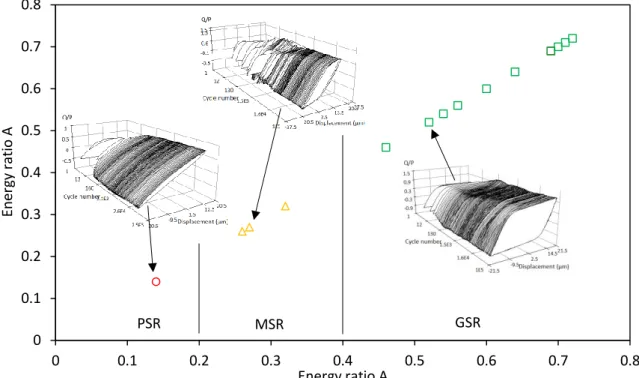
The concept of fretting map was initially proposed by Vingsbo et al. in 1988 [43]. In 1992, Zhou and Vincent [40] proposed two kinds of fretting maps: running condition fretting map (RCFM) and material response fretting map (MRFM), as shown in Figure I.6. The RCFM includes the PSR, MSR and GSR depending upon the fretting log and shows the boundary between these regimes in (normal force / displacement amplitude) axes. With the increase in displacement amplitude or the decrease in normal force, the fretting regime changes from the PSR to MSR and then to GSR. Through post-test examinations, the MRFM is divided into three domains: slight degradation, cracking and wear domains (Figure I.6). Concerning correspondence to the RCFM, slight degradation domain is mainly located in the PSR with very low displacement,while wear with severe particle detachment occurs in the GSR. Cracking lies within the PSR and the MSR [40, 44].
18
Figure I.6. Fretting maps: RCFM and MRFM [44].
2.4.3. Friction of metallic materials for implants
For femoral stems and neck adapters, they are normally made of metals (stainless steels, CoCr alloys, and Ti–6Al–4V alloys). For femoral heads, they are generally made of metals or ceramic. According to in vitro experiments, the friction coefficients of 316L, CoCr alloys, and Ti–6Al–4V alloys are relatively high (generally above 0.5) when they are sliding against another metal or against a ceramic.
Krishna et al. conducted sliding tests between an alumina ball and a 316L disc at room temperature and ambient conditions and the friction coefficients were in the range of 0.6–0.9 [45, 46]. Duisabeau et al. reported friction coefficients between 0.7 and 0.8 for a 316L cylinder sliding against a Ti–6Al–4V flat in air [47].
Chiba et al. conducted tests with a CoCr alloy pin sliding on a CoCr alloy disc and the friction coefficients were in the range of 0.5–0.7 [48]. Celik et al. reported the friction coefficient between 0.6 and 0.7 for a WC-Co pin sliding against a CoCr alloy disc at room temperature (around 18°C) and a relative humidity of about 50% [49].
Fridrici et al. reported high friction coefficients between 0.8–1.1 for a Ti–6Al–4V cylinder sliding against a Ti–6Al–4V flat under the GSR conditions [50, 51]. Itoh et al. studied the friction response of a steel ball sliding against a Ti–6Al–4V flat immersed in lubricant oil. The friction coefficient was relatively lower in the range of 0.5–0.6 [52].
19
2.4.4. Wear of metallic materials for implants
Stainless steel generally presents poor tribological properties and consequently high wear rates due to the low hardness [53, 54] and weak passivation layer [5]. Nickel-free steels have higher wear resistance compared to 316L [55]. Thomann et al. compared the wear resistance of the 316L steel (with the hardness of 155 ± 3 HV30) and of the nickel–free steel
(with the hardness of 367 ± 4 HV30) though pin-on-disk sliding wear tests [55]. The wear
volumes of nickel-free steel were approximately 70%–80% of the wear volumes of 316L. Cobalt–chromium based alloys have high wear and scratch resistance due to their higher hardness (300–400 HV10) among any biomedical alloys. Compared to 316L stainless steel,
CoCrMo alloy has a 10 times lower wear rate [5]. The microstructure and the manufacturing process influence the wear resistance of cobalt–chromium based alloys [56]. The wrought components exhibit better wear resistance than cast components and lower carbon cobalt– chromium alloys have lower wear rates [5, 57].
Titanium alloys generally have relatively low wear resistance primarily due to the instability of their surface layer, low resistance to plastic shear, high adhesiveness and low work hardening ability [5]. Therefore, they are generally not used for sliding conditions against each other. Wear resistance for titanium alloys can be enhanced by using modern manufacturing technologies (such as powder metallurgy) and surface modifications. The surface thermal oxidation treatment improves the wear resistance of Ti–6Al–4V in corrosive environments [58, 59].
2.4.5. Corrosion of metallic materials for implants
The body fluid is present in the hip joints [60–62]. The local solution chemistry could accelerate the corrosion process of the metal-on-metal contacts [63]. Stainless steels containing at least 11 wt.% of chromium have generally good corrosion resistance, which even improves with the increase in the chromium content due to the formation of a protective chromic oxide (Cr2O3) layer [5, 16]. The corrosion resistance of CoCr-based alloys is far greater
than the stainless steels owing to their high chromium content and the formation of the protective oxide layer [16]. The titanium alloys are superior in corrosion resistance to the stainless steels and CoCr alloys. Their excellent corrosion resistance is provided primarily by the protective TiO2 surface layer [5].
Once the corrosion process is coupled with fretting at the contact surfaces, known as the fretting-corrosion, it produces very large scale destructive damage mode at the interface. The mechanical processes lead to the removal of the protective oxide layer while the electrochemical processes cause the repassivation of the oxide layer [61].
20
2.4.6. Fracture failure of modular hip implant components
Implant fracture at the neck adapter / femoral stem contact has been increasingly reported [64]. Grupp et al. investigated 5 000 titanium neck adapters which were implanted between August 2004 and November 2006 [3]. Until the end of 2008, 1.4% (n=68) of the implanted neck adapters failed with an average time of 2.0 years (0.7 to 4.0 years) postoperatively. Figure I.7a shows a typical X-ray of a failed titanium neck adapter. After market launch in the year 2004, an increasing number of neck fractures of the Metha Short Hip System (Aesculap AG, Tuttlingen, Germany [3, 65]) occurred. Neck fractures were almost only observed for the titanium neck adapter and titanium stem combination. In 2006, Metha Short Hip System was taken off the market and re-introduced with cobalt–chromium neck adapters in 2007. However, the H-Max M design (Limacorporate, Villanova di san Daniele (UD), Italy [66]) just has sporadic neck failures and is still using the titanium neck adapter and titanium stem combination [4]. It is still unclear why the titanium neck adapters tends to fail in one system while functions well in another system. Wodecki et al. reported a fracture of the femoral stem (as shown in Figure I.7b and Figure I.7c) [67]. The fracture of the femoral stem has not yet been often described in the literature.
Figure I.7. (a) X-ray of a failed neck adapter [3], (b) x-ray and (c) photo of a failed stem [67].
It seems that fractures often occur slightly below the proximal end of the stem in a mechanically stressed region with high bending loads [4]. Except sudden high forces during patient’s activities, the micromotions on the neck adapter / femoral stem interface might lead to fretting-induced fatigue and might be responsible for initiating the failure mechanism [4].
It can be concluded from Section 2 that, stainless steels, CoCr alloys, Ti–6Al–4V alloys are widely used materials for the neck adapter and femoral stem components. The neck adapter / femoral stem is under fretting condition during walking. However, the metals (stainless steels, CoCr alloys, Ti–6Al–4V alloys) present poor tribological properties, including high friction coefficients (generally above 0.5) and poor wear resistance. Furthermore, the
21 induced fatigue on the neck adapter and femoral stem surfaces might lead to fracture failures. In order to improve the durability of neck adapter and femoral stem components, their tribological properties should be improved.
Coatings have been widely used to protect metallic substrates in many applications [68– 72]. Various types of coatings have been produced. And particular coatings might be suitable to the neck adapter / femoral stem contact to reduce the friction and wear. The coating types and deposition techniques will be discussed in the following sections.
3. Coatings for tribological applications
Coatings are widely used to control friction and wear in many kinds of sliding contacts [68–72]. In the last decades, many new deposition techniques were developed and an increasing number of coatings are available [73].
3.1. Type of coatings
For convenience, coatings could be divided into two broad categories according to their hardness: soft coatings (coating hardness less than 10 GPa) and hard coatings (coating hardness higher than 10 GPa) [74, 75], as shown in Figure I.8.
Figure I.8. Categories of coatings [75].
3.1.1. Soft coatings
The advantage of using a soft coating to a hard substrate is the reduced friction [72]. The reduction of friction can be explained according to the macromechanical friction mechanism proposed by Holmberg [72]. When a ball is sliding on a flat, the frictional force is ideally the product of the shear strength and the contact area. A harder flat can result in a decreased contact area but an increased shear strength. A softer flat can cause a decreased shear strength but an increased contact area. The combination of a soft coating and a hard substrate could reduce both the shear strength and the contact area, thus the friction force. Soft coatings include polymer coatings (such as, polytetrafluorethylene (PTFE), polyimides,
22
elastomers) [75, 76], soft metal coatings (such as, lead, silver, gold) [77, 78], lamellar coatings (such as, molybdenum disulfide (MoS2), graphite) [79, 80], etc.
3.1.2. Hard coatings
A hard coating on a soft substrate can reduce the wear of the substrate [72, 83]. Low friction can be achieved if a tribofilm with low shear strength is formed on the top of the coating, or/and on the countersurface. Thus, the low shear strength takes place within the tribofilm and the load is supported by the hard coating. Hard coatings include ceramic materials (such as, TiN [75, 85–88], Al2O3 [75, 89–91]), and covalent hard materials [92–95]
(such as, B4C, SiC, diamond [94–96], diamond-like carbon), etc. The properties of widely used
hard materials for coatings are shown in Table I.3.
Table I.3. Properties of some hard materials [75, 84]. Material Formula Density
(g/cm3) Melting point (°C) Hardness (HV) Young’s modulus (GPa) Thermal expansion coefficient (α) (10-6K-1)
Titanium nitride TiN 5.40 2950 2100 590 9.4
Titanium carbide TiC 4.93 3067 2800 470 8.3
Titanium diboride TiB2 4.50 3225 3000 560 7.8
Corundum Al2O3 3.98 2047 2100 400 8.4
Boron carbide B4C 2.52 2450 4000 441 4.5
Silicon carbide SiC 3.22 2760 2600 480 5.3
Diamond C 3.52 3800 8000 910 1
TiN is one of the widely used hard coatings in tool industries [86]. It is able to form a coherent or semi-coherent interface with metallic substrates [75]. Furthermore, it presents high chemical inertness, high temperature stability, and abrasive wear resistance [86].
Al2O3 coatings have been applied in industries because of their high temperature stability,
high melting point, good wear resistance, excellent corrosion resistance, and high insulation [89, 90].
Covalent hard materials (such as, B4C, SiC, diamond) have been used in many applications
because of their high hardness, high elastic modulus and high chemical stability [92]. The main disadvantage of such coatings is the poor cohesion to the metallic substrates, which may lead to early delamination of coatings [93]. Diamond-like carbon (DLC) coatings can overcome this problem in some extent because they have relatively lower hardness and lower elastic modulus, thus greater cohesion, depending on the deposition process, composition and structures of coatings [97]. DLC coatings also exhibit excellent tribological properties such as low friction and wear resistance. Furthermore, DLC coating has been used in orthopedic applications due to its biocompatibility [6]. The structure, deposition mechanism, mechanical and tribological properties, and biocompatibility of DLC coatings will be discussed in detail in Section 4.
23
3.2. Coating deposition methods
The progress of coating deposition techniques promotes the improvement of existing coatings and causes new generations and new types of coatings. A given deposition method can produce various types of coatings, and a given coating can be produced through various deposition methods. The most common deposition methods for tribological coatings include bonding, ion beam deposition (IBD), physical vapor deposition (PVD), CVD, etc. [68].
3.2.1. Bonding
A bonding process has been widely used to produce solid lubricant coatings which possess low friction coefficients and mitigate wear, adhesion and scuffing of mechanical parts [98]. Solid lubricant particles, such as MoS2, graphite and PTFE, are mixed into a resin system,
which contains binder, solvent, and modifier, etc. [99]. After that, the liquid mixture is applied on the substrate surface through immersion, brushing, or spraying, etc. [68]. And then the coating should be dried and hardened at a suitable temperature for an appropriate time period [68]. Similar to most deposition techniques, the substrate surface should be pretreated before the deposition process to improve the bonding strength of coatings on the substrates, such as degreasing via ultrasonic cleaning and roughing via sand blasting [68]. The biggest advantages of bonded coatings are the cheap technical process and large thickness they can achieve [100].
3.2.2. IBD
The IBD technique has been used to grow thin films at low temperatures and to synthesize a variety of materials such as oxides, nitrides, and silicides at surfaces [101]. The principle process of IBD is shown in Figure I.9. It mainly consists of an ion source, the ion extraction system and the substrate [102]. In the ion source, source materials in the form of a gas, an evaporated solid, or a solution (liquid) are ionized. After that, ions are accelerated, focused or deflected using high voltages or magnetic fields. Then the selected ions can reach the substrate. Thus, IBD has the ability to select a single or a range of ion species for deposition, in order to avoid contamination.
Figure I.9. Schematic illustration of IBD process [103].
3.2.3. PVD
PVD refers to the deposition processes in which material is vaporized from a solid or liquid source in the form of atoms or molecules and transported in the form of a vapor through a vacuum or low pressure gaseous (or plasma) environment to the substrate, where it
24
condenses [104, 105]. PVD processes can be used to deposit coatings of elements (such as DLC), alloys, and compounds (such as TiN and TiC). Typically, the thickness of PVD coatings is in the range of a few nanometers to several micrometers [104]. The main categories of PVD processing are vacuum deposition (sometimes called vacuum evaporation), sputter deposition, ion plating, etc. as shown in Figure I.10.
Figure I.10. PVD processing techniques [104].
Vacuum evaporation
In the vacuum evaporation process, the coating materials are heated to vaporize using tungsten wire coils or high energy electron beam, then transported through a vacuum environment to the substrates surface where solid coatings condense. The trajectory of the vaporized material is “line-of-sight”.
Sputter deposition
In the sputter deposition (sometimes called sputtering) process, particles are vaporized from a target surface through bombardment by atomic-sized energetic particles, which are usually gaseous ions, accelerated from plasma. The sputter deposition can be performed in vacuum using an ion gun or low pressure plasma (<5 mTorr), or in higher plasma pressure (5– 30 mTorr).
Ion plating
In the ion plating processes, the depositing material may be vaporized either by evaporation, sputtering, or decomposition of a chemical vapor precursor. The characteristic process of ion plating is that the depositing coating is bombarded concurrently or periodically by atomic-sized energetic particles to modify and control the properties of the coating. The energetic particles used for bombarding the coating are usually ions of an inert or reactive gas, or, in some cases, ions of the condensing coating materials. The ion plating may be performed in a plasma environment where the bombarding ions are extracted from the plasma or
25 performed in a vacuum environment where the bombarding ions are formed in a separate ion gun. The latter ion plating process is often called ion beam-assisted deposition (IBAD).
PVD process has a number of advantages. The main advantage is the low temperature of the substrate during deposition. The limit of DLC process is its low achievable thickness, because of the high internal stresses.
3.2.4. CVD
CVD refers to a family of processes that a solid material is deposited from a vapor by a chemical reaction occurring on or in the vicinity of a normally heated substrate surface [106– 108]. It is a widely used method to produce coatings of metals, nonmetallic elements (such as silicon and DLC), compounds (such as carbides, nitrides, and oxides), as well as other materials [68]. There exists a multitude of CVD processes, as shown in Table I.4.
Table I.4. Summary of CVD process family [108, 109]. Type Description Atmospheric pressure CVD
(APCVD)
Processes at atmospheric pressure Low-pressure CVD (LPCVD) Processes at subatmospheric pressures
Ultrahigh vacuum CVD (UHVCVD)
Processes at a very low pressure
Aerosol-assisted CVD (AACVD) Precursors are transported to the substrate by means of a liquid or gas aerosol, which can be generated ultrasonically
Direct liquid injection CVD (DLICVD)
Precursors are in liquid form (liquid or solid dissolved in a
convenient solvent). Liquid solutions are injected in a vaporization chamber towards injectors (typically car injectors). Then the precursor’s vapors are transported to the substrate as in classical CVD process
Plasma-assisted CVD (PACVD) Plasma-enhanced CVD (PECVD)
Utilizes a plasma to enhance chemical reaction rates of the precursors, and allows deposition at lower temperatures Atomic layer CVD (ALCVD or
ALD)
Deposits successive layers of different substances to produce layered, crystalline films
Hot wire CVD (HWCVD) Also known as catalytic CVD (Cat-CVD) or hot filament CVD (HFCVD). Uses a hot filament to chemically decompose the source gases Metal-organic chemical vapor
deposition (MOCVD)
Based on metal-organic precursors Hybrid physical–chemical vapor
deposition (HPCVD)
Vapor deposition processes that involve both chemical
decomposition of precursor gas and vaporization of a solid source Rapid thermal CVD (RTCVD) Uses heating lamps or other methods to rapidly heat the wafer
substrate
Vapor-phase epitaxy (VPE) Gases are decomposed and then meet and react on the substrate, generating an epitaxial film on the surface [109]
26
The principle in every CVD process is as shown in Figure I.11. Gaseous reactants are admitted into a reactor. Near or on a heated substrate surface, a chemical reaction occurs, generating a solid coating and gaseous byproducts. The CVD system generally includes three parts: gas dispensing system, reactor, and exhaust system [108].
Figure I.11. The principle of CVD [108].
Gas dispending system
In the gas dispensing system, reactants, which are gases at room temperature, are stored in gas bottles, and are flowed into the reactor under controlled pressure and flow rate. Reactants, which are liquid or solid at room temperature, are heated above the boiling or sublimation point using an evaporator or sublimator. The material is transferred to the vapor by evaporating or sublimation (solid gas) and then transported to the reactor by carrier gas. Reactor
There are two main reactor types: hot wall reactor and cold wall reactor. In a hot wall reactor, the reactor is surrounded by a furnace. The substrates and walls of the reactor all have the same temperature.The coating grows not only on the substrate but also on the wall. There is a risk that particles will break loose and fall down on the surface of the growing coating, thus introducing pinholes. In a cold wall reactor, the substrates are heated; however the walls of reactor are unheated and, as a result, no deposition occurs on the walls. Various techniques exist for heating the substrates. Conductive substrates can be heated resistively or by radiofrequency induction. Non-conductive substrates are normally heated by optical techniques (tungsten filament lamps, lasers), thermal radiation techniques, or by susceptors and radiofrequency induction.
Exhaust system
The exhaust system contains a vacuum pump, total pressure control, scrubbers, and a recycling system (if needed). Processes working at atmospheric pressure do not require vacuum pumps and total pressure control.
CVD process has a number of advantages. One of the primary advantages is that CVD coatings are generally quite conformal, which means that the CVD coatings can be applied on complex-shaped substrates [106]. In contrast, PVD techniques, such as sputtering or evaporation, require a line-of-sight between the substrate surface and the source. CVD also has disadvantages. One primary disadvantage is the high substrate temperature, which may
27 induce the distortion of the substrates. Fortunately, PECVD utilizes a plasma to enhance chemical reaction rates of the precursors, and allows deposition at lower temperatures [108].
4. DLC coatings
DLC is a metastable form of amorphous carbon with significant sp3 bonding [97]. DLC
coatings offer outstanding properties such as low friction coefficients, high hardness, wear resistance, chemical inertness, optical transparency in the infrared radiation spectral range and low electrical conductivities [110]. Thus, they have been widely used as protective coatings in areas like magnetic storage disks and read/write heads [111, 112], car and engine parts [113, 114], biomedical implants [115–118] and cutting and forming tools [119, 120].
4.1. Structure of DLC
A carbon atom has four valence electrons. They can exist in three hybridizations: sp3, sp2
and sp1, as shown in Figure I.12 [97, 121, 122]. In the sp3 configuration, all the four valence
electrons enter tetrahedrally directed sp3 orbitals. Each sp3 orbital makes a strong σ bond to
an adjacent atom. In the sp2 configuration, three valence electrons enter trigonally directed
sp2 orbitals, which form σ bonds in a plane. The forth valence electron enters a π orbital with
a normal direction to the σ bonding plane. This π orbital forms a weaker π bond with one or more neighboring atoms. In the sp1 configuration, two of the four valence electrons enter σ
orbitals, which form σ bonds in the directed of ±x-axis, and the other two valence electrons enter π orbitals in the y and z directions.
The strong σ bonding results in many extreme physical properties [97, 123]. Like diamond, it has a wide 5.5 eV band gap, the smallest thermal expansion coefficient and the highest hardness of any solid material on Earth. DLC consists of a significant fraction of sp3 hybridized
carbon [124]. The remaining is sp2 and occasionally sp1, generally containing various quantities
of hydrogen [125]. DLC has some extreme properties similar to diamond, such as the hardness, elastic modulus and chemical inertness, due to its high fraction of σ bonds.
Figure I.12. The sp3, sp2, and sp1 hybridized bonding [97].
Structural models of DLC have been produced since the 1980s [110, 126–129]. Representatively, Robertson and O’Reilly proposed a cluster model [6, 7]. According to the cluster model, DLC contains both sp3 and sp2. The sp3 forms four σ bonds while the sp2 forms
three σ bonds and one weaker π bond. The π bonds are stabilized by forming parallel oriented pairs. After that, they are stabilized by forming planar 6-fold aromatic rings. Then, the rings
![Table I.2. Mechanical properties of 316L steel, CoCrMo based alloys, and Ti–6Al–4V alloy [5, 21, 22]](https://thumb-eu.123doks.com/thumbv2/123doknet/14717459.750468/25.892.107.787.862.1108/table-mechanical-properties-steel-cocrmo-based-alloys-alloy.webp)
![Figure I.20. Influence of ion energy [146] and substrate temperature [147] on hardness and Young’s modulus of DLC coatings.](https://thumb-eu.123doks.com/thumbv2/123doknet/14717459.750468/46.892.167.722.328.615/figure-influence-energy-substrate-temperature-hardness-modulus-coatings.webp)