HAL Id: hal-02416217
https://hal.archives-ouvertes.fr/hal-02416217
Submitted on 24 Mar 2020
HAL is a multi-disciplinary open access
archive for the deposit and dissemination of
sci-entific research documents, whether they are
pub-lished or not. The documents may come from
teaching and research institutions in France or
abroad, or from public or private research centers.
L’archive ouverte pluridisciplinaire HAL, est
destinée au dépôt et à la diffusion de documents
scientifiques de niveau recherche, publiés ou non,
émanant des établissements d’enseignement et de
recherche français ou étrangers, des laboratoires
publics ou privés.
isothermal and thermo-mechanical loadings for a type
304-l stainless steel used for pressurized water reactor
C. Gourdin, G. Perez, P. Le Delliou, T. Metais
To cite this version:
C. Gourdin, G. Perez, P. Le Delliou, T. Metais. investigations on crack propagation under
cycli-cal isothermal and thermo-mechanicycli-cal loadings for a type 304-l stainless steel used for
pressur-ized water reactor. International Fatigue Congress, May 2018, Poitiers, France.
�10.1051/matec-conf/201816519004�. �hal-02416217�
Investigations On Crack Propagation Under Cyclical Isothermal
And Thermo-mechanical Loadings For A Type 304-L Stainless
Steel Used For Pressurized Water Reactor
Cédric Gourdin1,*, Gregory Perez1, Patrick Le Delliou2, and Gaëlle Leopold2
1DEN-Services d’Etudes Mécaniques et Thermiques (SEMT), CEA, University of Paris-Saclay, F-91191 Gif-sur-Yvette, France 2EDF, R&D, Site des Renardières, F-77818 Moret sur Loing Cedex, France
Abstract. The integrity of structures exhibiting flaws in Pressurized Water Reactor (PWR) has to be assessed to meet safety criteria. This paper deals with crack-propagation under cyclic thermo-mechanical loadings, as encountered in class I austenitic pipes of PWR’s. To have a conservative and reliable assessment of the crack propagation due to the in-service loading, various codes and standards use simplified method. For example, the RSE-M Code introduces a plastic correction depending on the proportion of the mechanical loading. An improvement of the current method requires additional investigations. Moreover, components loaded with transient or thermal fluctuations are not really in load-controlled conditions. To this end, a device called PROFATH was designed. The specimen is a pre-cracked thick-walled tube undergoing a set of thermal cycles and loaded with a static mechanical force. During the first part of the thermal cycle, a high frequency induction coil heats the external wall of the tube. Then, the heating system stops and the specimen is cooled down by running water inside the tube. Finite element calculations show that only a region half-way along the tube should be heated to ensure adequate structural effect. In the heated zone, the machining of a sharp circumferential groove ensures the propagation of a unique crack. An electro-mechanical jack controls the level of the mechanical static load. Tests have been carried out, and these tests allow having an evaluation of the pertinence of the correction proposed by the RSE-M Code for a significant plasticity.
1 Introduction
In operating conditions, components such as train wheels, engine pistons, moulds, brazing of electrical devices or turbine blades are submitted to cyclic loadings which have thermal origins [1]. In nuclear power plants, thermal fatigue has firstly been observed in fast breeder reactor (FBR) and then, in some components of pressurized water reactors (PWR) [1 to 3]. In particular, cyclic thermal loadings may lead to multi-cracking, such as the thermal fatigue crazing [4]. In that frame, investigations on thermal loading have been undertaken using specific devices [5 to 8].
This present study focuses on the crack-propagation under cyclical thermo-mechanical loadings, as may be encountered in Pressurized Water Reactor pipes: thermal loadings may correspond to an incomplete mixing between cold and warm fluids, or thermal stratification... Mechanical loadings may result from water pressure itself, or may be bending moments induced by the boundary conditions and piping configuration. In order to estimate an eventual crack-propagation, the French RSE-M Code proposes to apply a plastic correction for ductile materials [9]; so, this correction concerns particularly the austenitic stainless steels (as AISI 304-L
steel) [10]. In that frame, stress intensity factor range (ΔK) is deduced first from a linear elastic fracture mechanics analysis (LEFM), and is corrected after as:
(
a r)
/a K KCP =a∆ + y ∆ (1) where: ry =1/6π(
∆K /2Sy)
2 (2)Sy is the conventional yield stress YS0.2 (0.2% yield
stress).
In a case of pure thermal fatigue, a is simply taken equal to 1, whereas a a correction is proposed when the mechanical part of loading becomes significant (
max meca max 0.2K K > ): 1 = a whenry≤0.05
(
W−a)
(3)(
)
[
0.05 /(0.035.( ))]
2 15 . 0 1+ ry− ⋅W−a W−a = a When 0.05(
W−a)
<ry≤0.085(
W−a)
(4) 15 . 1 = a when ry>0.085(W−a). (5)However, such methodology must be improved, particularly in the cases of cyclic thermo-mechanical loadings. For nuclear power plant components, thermal loading corresponds to restraint to thermal expansion, and thus mainly to strain-controlled loading. In that frame, crack propagation leads to some mechanical unloading in the un-cracked zone. In such way, methodologies based only on load-controlled tests cannot be very efficient.
In order to improve the estimation of crack propagation under cyclic thermal loading, a new device called PROFATH has been built in our laboratory. In that one, specimens are submitted in the same time to cyclic thermal loading and to constant tensile loading. This paper details the preparation of the tests and the first thermal maps obtained on this new device. However, present study begins with a crack propagation campaign performed for isothermal conditions on CT specimens.
2 Presentation of the
thermo-mechanical device: PROFATH
- Specimen geometry: Specimen is a thick pipe (Fig 1). Despite cracks appear preferentially at the inner wall for real components (such as thermal fatigue crazing), crack is placed at the external wall. Such configuration allows better crack-opening measurements and facilitates the crack observations during the intermediate test stops. Calculation of mechanical fields with such geometry is relatively simple, since it corresponds to axisymmetric conditions. All the thermal and mechanical calculations have been made using finite element meshing; used software is the CEA code Cast3M [13]. Dimensions of specimen are taken as 60 mm outer diameter, 10 mm thickness and 300 mm length.
- Thermal loading: All the preliminary test calculations were made with a 30°C-300°C thermal cycle. In order to reduce the heating phase time, an external high-frequency eddy-current heating is placed around the crack plane. The maximum temperature of the outer wall is reached in about 30 s (Fig 1). Then, the temperature of the external wall is maintained until the temperature radial gradient goes down close to 10°C. After, heating is stopped and water-cooling of the inner wall is started. This second phase leads to a reduction of the temperature of the outer wall to 30°C. After a very brief air injection (0.5 s) to empty the inner wall of the specimen, a new cycle can be started.
Fig 1. Test principle schematic and thermal cycle.
Stress calculations (Fig 2) clearly emphasize that a local heating is very well-adapted in the present case, since the external wall is mainly submitted to tensile stresses. In fact, such behavior results from component constraining effect: the un-heated part leads to severe constraining conditions, and induces bending stresses. Calculations show that maximum stresses and constraining effect are obtained for a 30 mm local length heating (15 mm for the half-specimen) as it is presented in Fig 2.
Fig 2: Finite-element meshing of the local heating
design (CEA software Cast3M) and evolution of maximum stress as a function of heated half length
- Additional mechanical loading: Uniform tensile stress on specimen is simply obtained with the electric actuator of a DELTALAB tensile machine. PROFATH system is
Time Time Tc Th Th Tc Heating time Cooling timer Thermal cooling by water circulation
Thermal loading (heating) by high frequency induction
Thermal loading height -400 -300 -200 -100 0 100 200 300 400 0 10 20 30 40 50 60 70 80 Ma xi m al S tr es s ( ope nni ng , MP a)
Height of the thermal loading - Heating- (mm)
Int Ext
integrated between its columns, below the 200 kN capacity actuator, as shown in Fig 3.
- Instrumentation: Data acquisition and test control are provided by the joint use of a NATIONAL INSTRUMENT CompacDAQ device and CEA specific software written with LABVIEW.
Heating is devoted to a FIVE CELES high frequency generator. The 6 kW power is controlled by software through the 4/20 mA input of the generator. The water and air injection valves are also software controlled. Accurate thermal mapping as a function of time are built from 0.5 mm diameter K-thermocouple measurements. Thermocouples can be placed at several depths (attached on outer wall, and 5 and 9 mm deep from outer wall), axial (7 values) and angular (0, 120, 240°) positions (Fig. 6).
- Mechanical centering: Strain gauges are positioned at the lower part of the specimen to allow an initial mechanical centering of the device.
- Crack length estimation: The use of an INSTRON extensometer placed above the crack plane makes a compliance measurement possible. Thanks to FE calculations, the equation linking compliance and crack length has been established.
Fig 3: PROFATH device.
Fig 4: Location of the thermocouples.
3 Experimental device optimisation
- Cooling: Many preliminary tests were performed with two types of water cooling injection devices mentioned as "spherical injector" and "turning injector" and for different axial positions from the circular groove. Finally, chosen conditions are: a water flow rate of 12 l/min, a cooling temperature of 17°C or less, a "spherical injector" placed at the circular groove plane. Such conditions give a cooling time of about 50 seconds. A Plexiglas specimen was used to identify the water behavior during injection with the two types of injector (Fig. 5). Pictures are obtained using a high speed camera (1000 pictures per second). Optical observations lead us to highlight that spherical injector brought less air in theflow of water than the rotating one. This explains its better cooling efficiency.
- Heater selection: The purpose of the heating phase is to
heat the entire thickness of the tube quickly before the thermal conduction spreads longitudinally. Initial tests have been performed with FIVE CELES to choose the generator and induction coil characteristics. Tests performed with specific specimen observed with a FLIR Infrared camera allowed us to choose a frequency of 100 kHz and a power of 6 kW.
Fig 5: Comparison of rotating and spherical injector’s
behaviour
- Thermal map: Establishment of experimental thermal maps is required in order to qualify accurately the real thermal loads. A specific specimen instrumented with as many as 20 thermocouples is used. The thermocouples are placed at outer surface and along wall thickness in some positions, and at three circumferential positions. Test specimens are instrumented with 10 thermocouples. Only A (depth 9 mm) and C (surface) types are required in this case as explained in experimental part.
4 Experimental tests
Seven specimens have been tested. A test (n°5) was devoted to the study of the test specimen necking during testing.
The first test was devoted to develop and to validate the experimental process.
The experimental protocol has evolved through each test feedback. It can finally be synthesized through the following steps:
- Instrumentation of the specimen (extra thermocouples, strain gauges …)
- Mechanical alignment of the specimen on the PROFATH device
- Thermal cycling and static mechanical load
- Mechanical compliance every 250/500 cycles to monitor the crack propagation: adjustment of test conditions for each step
- Mechanical fatigue post cracking is achieved by using a hydraulic device with a capacity of 500 kN. A cyclic displacement is imposed to the specimen with a ratio of 0.4,
- Optical analysis of the fracture surface.
An overview of the loading evolutions and the final fracture surfaces are presented for test 3 (Fig. 6).
Fig 6: Overview of test n°3 with specimen 738C-A.
Fig 7: Overview of test n°6 with specimen 738D-B.
Application of dye penetrant product is performed for different intermediate steps during test. This one allows insuring optical measurements of the crack length after rupture. Let us note that such post-mortem values are in relative good agreement with estimates deduced from compliances as it is shown in Fig 7.
Fig 8: Crack propagation, comparison between estimates
from compliance performed during the test, and optical measurements performed after post cracking (test n°2).
5 Analysis
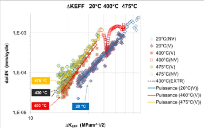
- Crack-growth rate tests in isothermal conditions: In isothermal conditions, the crack-growth rate tests have been carried out at 20, 200 and 475°C under load controlled conditions with a load ratio R of 0.1 (R = Kmin/Kmax).
Specimens are compact tension specimens (CT25). During the test, crack-length is continuously evaluated from compliance measurements performed with a clip-gage. Let us note that such estimations deduced from compliance are in good agreement with measurements performed on final crack and on intermediate marks; 2 or 3 marks per test have been obtained by modifying temporary the load ratio (1000 cycles) and applying a product used for dye penetrant inspection. Fig 8 presents the crack-growth rate da/dN as a function of the effective stress intensity factor range (ΔKEFF). This last value is
directly deduced from the stress intensity factor range by applying a multiplying factor q including both crack-closure and mean stress effects [10]; the relation is:
ΔKEFF=q*ΔK with: q=1/(1-0.5*R) when R≥0 (6)
A Paris’ law can be fitted for each investigated temperature; a significant influence of the temperature is clearly emphasized (Fig 8). Let us note that the Paris’ law fitting remains acceptable, even when the un-cracked length becomes too small to verify the condition of validity proposed by ASTM E-647 (open symbols and NV).
Fig 9: Crack-growth rate as a function of the effective
stress intensity factor (ΔKEFF) at different temperatures; the open symbols correspond to non-valid results; the dotted line corresponds to an interpolation at 430 °C. - Analysis: The thermo-mechanical calculations have been achieved using the CEA finite-element software Cast3M [13]. Only a thickness portion of the PROFATH specimen has been meshed, since asymmetrical condition can be considered. The meshing is detailed in Fig 1; elements are quadratics with 8 nodes (QUA8). At the crack tip, a very refined meshing is used, since the element size is reduced to only 30 microns.
A first step deals with thermal calculations; the aim is to reproduce the experimental information obtained with
thermocouples and thermal maps obtained with FLIR Infrared camera (Fig. 10). Calculations are performed for the maximal temperatures of 400, 450 and 500°C chosen for the PROFATH program. Let us note that temperatures are measured with thermocouples placed at ± 9 mm from the crack plane. So, the maximal temperatures at the crack are systematically 30 °C higher (Fig 11); this difference is in good agreement with preliminary experimental measurements performed on a specific calibration specimen. Furthermore, an acceptable agreement can be observed between experimental measurements and F-E calculations at ± 9 mm (Fig 12).
Fig 10: Thermal map obtained with FLIR Infrared
camera
Fig 11: Cast3M calculations at 400 °C, estimated
temperatures in the crack-plane (dotted line) and at ±9 mm from the crack plane (solid line), for outer wall, 5 and 9 mm deep.
Fig 12: Cast3M calculations at 400 °C, comparison
between estimated (solid line) and measured temperatures (dotted line) at ±9 mm from the crack plane and 9 mm deep.
In a second step, mechanical and fracture mechanics calculations are performed; crack-lengths are based on compliance estimations. As generally used for analysis on components and proposed by the RSE-M approach, calculations have been made with an elastic behavior. Initial geometry is considered in the present calculations; such analysis will be probably revised in the future when a best knowledge of the diameter contraction will be available. Application of a Paris’ law requires both a crack deep enough (referred as “mechanically long crack”) and intermediate SIF values (≥15 MPa√m). In this frame, the analysis begins when a crack-growth of 1 mm is reached from the initial machined groove.
The stress intensity factor (SIF) is deduced from the strain energy release rate using the G_THETA procedure of Cast3M; with a plane strain hypothesis. Fig 13 represents evolution of the SIF as a function of time. The maximum value is reached when the heating phase is ended; after, the SIF drops suddenly to a null value as soon as the water-injection starts; and it becomes equal to the mechanical component (Kmeca) solely when the
cycle is ended.
Fig 13: Cast3M calculations at 400 °C. Evolution of the
SIF as a function of time; in this particular case the crack-length is 5.33 mm and the duration of cycle is 120 s.
Fig 14 confirms that an elastic-plastic correction is required, since applying a simple elastic approach conducts to completely unacceptable underestimates of the fatigue-life. Besides, it emphasizes a good agreement between experimental values and RSE-M predictions.
Fig 14: Number of cycles, comparison between
predictions and experimental values for tests
- Conclusions about prediction methodology: A pure elastic fracture mechanics analysis conducts to severe underestimates of the fatigue-life. Consequently, such a methodology is completely not acceptable for thermo-mechanical loading, when the plasticity at the crack-tip is not negligible: when 0.05 (W-a) < ryA≤ 0.085 (W – a)
where W-a is the un-cracked length, ryAthe cyclic plastic
zone calculated using an Irwin’s relation.
An elastic-plastic analysis proposed by the RSE-M code conducts to good predictions; for this one a first step is based on elastic fracture mechanics calculation, a second step deals with application of plastic amplifying factor (α) and effective length (aeff= a+ryA).
6 Conclusions
In a first step, an isothermal test campaign was performed on CT-specimens with several loading conditions (0.10≤R≤0.80). It shows that application of a plastic correction (ry and a coefficient) is not indicated. A new device called PROFATH was built. Specimen is a thick-walled tube, and cyclical loadings are applied: in a
first part of the cycle, the external wall is heated by a high frequency induction coil, and in a second part of the cycle, heating is stopped and the internal wall is cooled by running water. Finite element calculations show that only a median portion of the tube must be submitted to cyclical thermal loadings to guarantee an important component effect. To be sure that only one crack will propagated, a sharp circumferential groove is machined in the heated portion. A tensile mechanical loading may be also applied on specimen with an electro-mechanical jack.
Thermal mapping is deduced using a specific specimen instrumented with as many as 20 thermocouples: they are placed at outer surface and along wall thickness in some positions.
After an experimental optimization phase seven tests have been performed on the PROFATH device and they have been exploited:
- The elastic estimation seriously underestimates the crack propagation and is non-conservative,
- RSE-M estimation provides relative close and conservative results.
Mr Tournié Ivan and Godin Marvin are very greatly acknowledged for participation to the mounting device.
References
1. Fissolo, A., Fissuration en fatigue thermique des aciers inoxydables austénitiques, CEA Report R-5982, Mémoire d’Habilitation à Diriger les Recherches; 2001. Université des Sciences et Technologie de Lille. 2. Nulife project, Pilot project on thermal fatigue – item 3, Document D(08) 25383, December 2008. 3. Cipière, M.F., Le Duff, J.A., Thermal fatigue experience in French piping. International Institute Of Welding, Document n°XIII-1981-01, Lubjana, 2001. 4. Fissolo, A., Marini, B., Multiple Cracking in Thermal Fatigue, European Congress on Fracture 12th, Proceeding p. 31, Sheffield, UK, 1998.
5. Ancelet, O. and al, « Development of a test for the analysis of the harmfulness of a 3D thermal loading in tubes », International Journal of Fatigue, Vol. 29, 549-564, 2007.
6. Fissolo, A., Marini, B., Nais, G., Wident, P. "Thermal fatigue behaviour for a 316 L type steel" Journal of Nuclear Materials, 233 – 237 (1996), 156 – 161.
7. Fissolo, A., Gourdin, C., Vincent, L. "Crack-initiation under Thermal Fatigue: An Overview of CEA experience", 35th MPA Seminar, 9 October 2009, Stuttgart (Germany).
8. Bouin, P., Fissolo, A., Gourdin, C. "An
experimental and numerical methodology to investigate on crack growth in a 304-L austenitic stainless steel pipe under thermal fatigue". Proceedings of the ASME 2010 Pressure Vessels and Piping Division/ K-PVP
Conference, presented July 18 – 22, 2010, Bellevue, Washington, USA.
9. Code RSE-M – Modificatif 2005, Annexes 5.3 et 5.6.
10. RCC-MRx, « Règles de Conception et de
Construction des Matériels Mécaniques des Installations Nucléaires applicables aux structures à haute
température et à l'enceinte à vide ITER », AFCEN Code, Association Française pour les Règles de Conception et de Construction des chaudières Électronucléaires. www.afcen.com, 2012.
11. Produits métalliques – Pratique des essais de fissuration par fatigue. Norme AFNOR A03 – 404, 1991. 12. Standard Test Method for Measurement of Crack Growth Rates. American Society for Testing and Materials, ASTM 647, 1993.