HAL Id: hal-01609110
https://hal.archives-ouvertes.fr/hal-01609110
Submitted on 7 Nov 2018
HAL is a multi-disciplinary open access
archive for the deposit and dissemination of
sci-entific research documents, whether they are
pub-lished or not. The documents may come from
teaching and research institutions in France or
abroad, or from public or private research centers.
L’archive ouverte pluridisciplinaire HAL, est
destinée au dépôt et à la diffusion de documents
scientifiques de niveau recherche, publiés ou non,
émanant des établissements d’enseignement et de
recherche français ou étrangers, des laboratoires
publics ou privés.
Control systems for direct steam generation in linear
concentrating solar power plants
Antoine Aurousseau, Valery Vuillerme, Jean-Jacques Bézian
To cite this version:
Antoine Aurousseau, Valery Vuillerme, Jean-Jacques Bézian. Control systems for direct steam
genera-tion in linear concentrating solar power plants: a review. Renewable and Sustainable Energy Reviews,
Elsevier, 2016, 56, p. 611-630. �10.1016/j.rser.2015.11.083�. �hal-01609110�
Control systems for direct steam generation in linear concentrating
solar power plants – A review
Antoine Aurousseau
a,b,n, Valéry Vuillerme
a, Jean-Jacques Bezian
baUniv. Grenoble Alpes, INES, CEA, LITEN, Laboratoire des Systèmes Solaires Haute Température, F-33375 Le Bourget du Lac, France bUniversité de Toulouse, Mines Albi, CNRS, Centre RAPSODEE, France
Keywords:
Concentrating Solar Power Line-focus
Direct steam generation Control systems
a b s t r a c t
Concentrating Solar Power (CSP) plants generate renewable electricity using the conversion of solar direct normal irradiation into thermal energy, then into mechanical work and electricity through the use of a thermodynamic cycle. Among the several available technologies, Direct Steam Generation (DSG), in which steam is generated directly in the absorber tubes of the solar field, and then directly fed to the turbine or thermal storage, holds interesting advantages. However, the steam generation system shows a difficult dynamic behavior which constitutes a challenge for the control system design. It is mainly due to the conjunction of the natural transient condition of solar irradiation and the presence of two phase flow in the absorber tubes. This paper reviews the control methods of the DSG systems used in linefocus CSP. The control systems are either proposed in literature, or actually applied in currently running plants or prototypes, although an extensive description is difficult to obtain in the case of the latter. The control systems are classified according to which DSG operation mode they refer to.
Contents
1. Introduction . . . 612
2. Direct steam generation in linear concentrating systems . . . 612
2.1. Overall layout and physical considerations . . . 612
2.2. Operation modes for the direct steam generation . . . 613
2.2.1. Recirculation operation mode . . . 613
2.2.2. Once through operation mode . . . 614
2.2.3. Injection operation mode . . . 614
2.2.4. Considerations for the control system . . . 614
3. Control systems for the recirculation operation mode . . . 614
3.1. Control structures using solely PI with feedback . . . 615
3.1.1. Single row vaporizer and superheater control . . . 615
3.1.2. Multi row superheater outlet temperature and mass flow control. . . 616
3.2. Stuctures using feedforward control. . . 619
3.2.1. Vaporizer feedwater flow rate control . . . 619
3.2.2. Single superheater outlet steam temperature control . . . 619
3.3. Structures using “predictive” control: Separator level control with dead time compensation . . . 620
3.4. Summary . . . 621
4. Control Systems for the once through operation mode . . . 621
4.1. Outlet steam pressure and feedwater valve pressure drop control loops . . . 621
4.2. Feedforward control structure for the outlet steam temperature . . . 621
4.2.1. Feedwater valve control . . . 621
4.2.2. Injection cooling valve control . . . 624
4.3. Conclusions and perspective for once through mode . . . 624
nCorresponding author at: Univ. Grenoble Alpes, INES, CEA, LITEN, Laboratoire des Systèmes Solaires Haute Température, F-33375 Le Bourget du Lac, France.
5. Control systems for the injection operation mode. . . 624
5.1. Superheater modeling . . . 624
5.2. Superheater control system. . . 624
5.2.1. Adaptive PI control . . . 624
5.2.2. Internal Model Control . . . 625
5.2.3. Performance of the control systems . . . 626
5.3. Conclusion of the study of Eck and Eberl (1999) . . . 626
5.4. Work of Eck and Steinmann (2000) . . . 626
6. Results from experience on line focus DSG plants in operation . . . 628
6.1. The parabolic trough plant Thai Solar One . . . 628
6.2. The Fresnel plant Puerto Errado 1 . . . 628
6.3. The Fresnel plant Puerto Errado 2 . . . 629
6.4. The CLFR (Compact Linear Fresnel Reflector) SSG4 collector. . . 629
6.5. CNIM CLFR concept . . . 629
Acknowledgments. . . 630
References . . . 630
1. Introduction
In the context of a world where primary energy consumption is constantly increasing, and where the climate change most opti mistic scenario is now the limitation of the global average tem perature rise above pre industrial level to 2 °C, renewable elec tricity generation has a major role to play. Concentrated solar power (CSP) plants use the sun’s direct normal irradiation to generate electricity using an intermediate conversion into thermal energy and a thermodynamic cycle. Current installed capacity worldwide is about 4 GWe[1], which is still a low figure as com pared to photovoltaics. However, in its “hi Ren” scenario, the International Energy Agency envisions a CSP contribution to the global electricity production of about 11% by 2050[1]. It should be noted that this figure remains almost unchanged since the pre vious report [2], although CSP development was lower than expected in this intermediate period.
Among the several technologies used to collect heat in line focus CSP technologies, the use of water/steam as both heat transfer fluid (HTF) and working thermodynamic cycle fluid con stitutes the so called direct steam generation technology (DSG). It offers several advantages compared to the synthetic oil that is used in most line focus plants: the fluid is heated up to a higher temperature, and the overall configuration is simpler thanks to the absence of HTF piping and heat exchange components [3]. Although the potential of generating steam directly in the absor ber tubes was identified in the early 80’s[4], first studies to apply this technology to line focus systems go back to the early 90’s, with research effort regarding two phase flow inside horizontal tubes[3 5,6]. Since then, numerous studies and research projects have been carried out, many of which surrounding the DIrect Solar Steam(DISS) experimental facility in Almeria[7]. A recent review by Hirsch et al.[8]gives a good overview of today’s state of the art about direct steam generation. Recent studies about the potential of DSG compared to synthetic oil, considering the latest knowl edge and technologies, are also available. The studies by Eck et al.
[9] and Feldhoff et al. [10] show a potential reduction of the levelized electricity cost (LEC) up to 11%. They did not however include the use of thermal energy storage, which is a major asset of solar thermal electricity. This was done in a more recent study by Feldhoff et al.[11], in which it was shown that with the current state of the art on thermal storage, the LEC of a DSG plant could actually be higher than the one of an equivalent oil plant. Several leads are proposed to reduce the LEC, including the use of a spe cific DSG plant architecture, known as “once through”. That architecture is however less applied today, mainly because it requires a more complex control structure.
The control system design of a CSP plant is critical to its proper operation since it has to handle the natural transient condition of solar irradiation, and it is even more important in the case of a DSG system in which the magnitude of the transient phenomenon is increased by the presence of two phase flow inside the absorber tubes. The objective of this paper is to provide a state of the art of the control systems used for direct steam generation in line focus CSP plants. The focus is mainly on the methods proposed in lit erature, and the actually applied systems as well, although infor mation about operating power plants is difficult to obtain. In the first section of the paper, some general notions are given about DSG and how it is operated. The next three sections are dedicated to the control systems for each operation mode, and a last section focuses on operational experiences from the few currently running commercial plants. Advanced control being a vast and complex research field, some basic explanation is given each time a new control method is mentioned.
2. Direct steam generation in linear concentrating systems 2.1. Overall layout and physical considerations
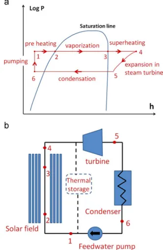
As many of the conventional power plants, CSP plants use a thermodynamic steam Rankine cycle to generate work that drives an electricity generator. It therefore seems obvious that generating steam directly in the solar field reduces the complexity of the overall system.Fig. 1below shows an ideal steam Rankine cycle (1a) and a simplified diagram of its application (1b) in a DSG plant (Fresnel collector is used for the schematic). Some details are also given for the involved thermodynamics processes. Numbered points on the figure refer to thermodynamic states between the described processes.
!
1-2-3-4: Isobaric heat transfer. Feedwater is pre heated to liquid saturation conditions either solely in the solar field or partly in a reheater and in the solar field. Water is then vaporized and steam is superheated in the solar field. Depend ing on the operation mode, vaporization and superheating take place in the same section, or separate sections. The process is ideally isobaric, but pressure drop actually takes place in the absorber tubes and the external piping.!
4-5: Isentropic expansion. Superheated steam decreases in enthalpy by being expanded in the turbine. The ideal process is isentropic, but entropy actually increases which leads to less energy transfer on the turbine blades. Depending on the powerblock setting, expansion brings steam to vapor saturation con ditions, or to superheated conditions again.
!
5-6: Isobaric heat rejection. Steam is desuperheated (if superheated conditions at 5), condensed, and subcooled in aheat exchanger. The process is once again ideally isobaric, but pressure losses are actually observed in the condenser.
!
6-1: Isentropic compression. Condensed water pressure is raised in the feed pump, and brought to the solar field operating pressure.Pre heating, vaporization, and superheating take place through different phenomena, each associated with its own thermo hydraulic properties. Pre heating and superheating are single phase convective heat transfer, with different heat transfer coefficients. Vaporization in the absorber tubes is a two phase convective flow boiling phenomenon, with very specific proper ties, and the scientific community still has relatively few knowledge of the precise dynamics taking place, in particular for horizontal configurations. Most of the calculations that are related to this field, pressures drops and heat transfer coefficients in particular, are only carried out through the use of empirical correlations.
2.2. Operation modes for the direct steam generation
Three main concepts, or operation modes, were identified in the early phase of the DISS project[12]: the recirculation concept, the once through concept, and the injection concept, all pictured
inFig. 2.
2.2.1. Recirculation operation mode
With recirculation, water is preheated and vaporized in a specific section, and superheated in another one. Water is fed at the inlet of the vaporizer, heated up to saturation conditions, and then vaporized, below vapor saturation conditions. The two phase fluid flows into a field separator, where steam is separated from the liquid water. A recirculation pump drives the liquid back to the vaporizer inlet, where it is mixed with the feedwater from the power block outlet, and saturated steam is fed to the inlet of the superheater. Steam quality at the vaporizer outlet is usually between 60% and 80%[8]. It should be high enough to avoid an excessively large recirculation pumping power (assuming feed water pumping is independently controlled, based on separator water level), and low enough to have a safety margin from tube dryout. The vaporizer outlet steam fraction can be defined by a
Fig. 1. Ideal steam Rankine cycle on a pressure-enthalpy diagram (left, a) and its layout in a DSG plant (right, b).
thermodynamic state, as shown in equation (1). xo is the outlet
steam quality, P the operating pressure, h0is the outlet flow spe
cific enthalpy, hsat;lthe specific enthalpy at liquid saturation, hsat;v.
the specific enthalpy at vapor saturation. Those last two terms depend on the vaporizer operating pressure P, which is usually assumed to be constant for design and energy balance computa tions
xo¼h h0 hi
sat;vðPÞ hsat;lðPÞ ð1Þ
Outlet specific enthalpy can be computed from an energy bal ance, knowing the absorbed heat from the incoming solar irra diation on the tubes walls. Inlet specific enthalpy can be computed through another energy balance with the mixing of the inlet flows: hi¼
QfeedhfeedþQrecirhrecir
QfeedþQrecir ð2Þ
With feedwater mass flow rate Qfeed; feedwater specific
enthalpy hfeed, recirculation mass flow rate Qrecir, recirculation
water specific enthalpy hrecir: Let r the ratio of the massflow rates:
r ¼Qrecir
Qfeed ð3Þ
Vaporizer inlet flow specific enthalpy may then be written as:
hi¼1þr1 hfeedþ1þrr hrecir ð4Þ
If pressure is assumed to be constant throughout the vaporizer and if no heat loss is assumed in the recirculation piping,
hrecir¼ hsat;lð ÞP ð5Þ
If feedwater flow rate and enthalpy are fixed, then outlet spe cific enthalpy, and thus steam quality, depends on only one con trollable parameter, the recirculation mass flow rate.
2.2.2. Once through operation mode
Once through is a solar field architecture where preheating, vaporization and superheating of the water/steam take place without separation. There is no water/steam separator at the end of the vaporizer section and the whole flow rate goes through the inlet of the solar field. Dry superheated steam is expected at the solar field outlet, and feedwater flow is at the enthalpy and pressure condition of the power block outlet. The transition points between preheating and vaporization and vaporization and superheating are not clearly predictable since the behavior of the system is very dynamic, but those positions can be roughly estimated.Fig. 3shows a simplified diagram of the flow inside a single horizontal absorber tube[13]. For sizing needs, using some assumptions in steady state conditions, one can estimate the positions where enthalpy reaches hsat;lðPÞ and hsat;vðPÞ, by simple energy balance computations.
2.2.3. Injection operation mode
With the injection architecture, several injectors are dispatched along the solar field such that the flow rate is injected in small quantities in each of them. As for the once through concept,
pre heating, vaporization and superheating take place in the same absorber lines. Knowledge of the transition regions is therefore also difficult, and the control systems designs require the assumptions that flow energy states are known at the injection positions. In the case of a parabolic trough collector field, the injections are done at the inlet of each collector.
2.2.4. Considerations for the control system
The steam generation has to be controlled with a system that strongly depends on the configuration itself, which is why it seemed appropriate to give some insight about DSG solar field architectures. The main requirement of the solar steam generation system is to provide live steam to the steam turbine and thermal storage at pressure and temperature conditions as stable as pos sible. In practice, because of the input energy transients, some being slow and deterministic (daily and seasonal cycles), some being fast and non deterministic (clouds passages), transients are almost impossible to avoid. Ideally, irradiation transients should only affect the amount of available steam, and not its quality (in the general sense). In the early studies of the direct steam gen eration concept, the issue of controllability of the convective flow boiling process was raised at the beginning [14]. This led to the fact that an important part of the subsequent research in the DISS program was dedicated to control strategies[12].
The bad tolerance of the turbine blades to large temperature transients is one of the reasons why temperature stability is to be achieved as best as possible, with the objective of avoiding large temperature overshoots and drops. Steam turbines have been working now for more than a century, and standards[15]from the International Electrotechnical Commission(IEC) are available. From this standard, limits about the steam quality at the inlet can be extracted. Birnbaum et al.[16] summed them up, and presented them as inFig. 4.
In terms of absolute temperature, the value not to be exceeded appears to be 28 K above the rated condition. In terms of tran sients, the standards do not mention the allowable values during turbines operation, as they are specific to the models and manu facturers. However, the authors mention a rule of thumb that turbines in the range of 50 to 150 MW should not go through temperature transients larger than 5 K per minute.
As it is presented in the following sections, most control sys tems make the use of a PI controller, whether solely or as a part of a more complex structure. In both cases the issue of its parameters definition is to be addressed. Controller parameters tuning is a very vast research area, and is not in the scope of this study. However, the specific tuning methods that are used in the field of line focus direct steam generation are presented. Most of the time, the process to control is modeled with transfer functions, useful for studying dynamic behaviors. From the transfer functions, parameters tuning can be carried out, and methods are explained in the dedicated sections.
3. Control systems for the recirculation operation mode From simple PI and feedback to more complex structures, this section aims at summing up the different control structures pro posed in the literature to control a DSG solar field using the recirculation concept.
This concept solves the issue of the engineers and researchers’ inability to exactly predict the location of the end of vaporization in the tubes. Indeed, more water that can be vaporized is injected in the evaporator, leading to a steam fraction below unity at the outlet. This architecture implies a more complex and costly solar field, as more equipment is needed: field separator, supplementary piping (and therefore more pressure losses), a recirculation pump (and therefore
more parasitic electricity consumption). However, the concept offers more stability by bringing more inertia to the steam generation and adds a controllable parameter, the recirculation flow rate, which has a significant impact on the steam quality. The uncertainty of the transition between saturated and superheated steam also leads to durability and safety issues in the case of the once through mode, which is not the case with recirculation.
3.1. Control structures using solely PI with feedback 3.1.1. Single row vaporizer and superheater control
Earlier research work on the recirculation operation mode was carried out with the DISS loop in Almeria. Valenzuela et al.[17]
propose a feedback control system, based on proportional integral controllers, pictured inFig. 5.
Starting with the superheating section, the proposed control loops for this configuration are detailed below. Describing these loops also gives some insight about the main dynamics of the system.
!
Outlet superheated steam temperature control loop: the temperature is controlled by a valve that injects feedwater in the last collector. “Fresh” water is injected into the superheated steam and instantly vaporized to decrease temperature;!
Outlet superheated steam pressure control loop: live super heated steam flows into a final separator before being fed to theFig. 4. Limits of steam and pressure at turbine inlet, according to standards[15], and presented by (and reprinted from)[16].
turbine. Pressure is maintained constant by the adjustment of a valve aperture. The solar field therefore works in constant pressure mode;
!
Final separator liquid level control loop: an on off control is used to avoid a high liquid level in the superheated steam separator;!
Recirculation control loop: in the vaporizer, recirculation is maintained to a constant flow rate by controlling the recircu lation pump. This control is necessary because irradiation transients on the receivers generate strong changes in pressure drop across the pump. This type of control therefore does not include steam fraction control at the vaporizer, but makes the operation safer since a minimal flow rate is always ensured;!
Separator level control loop: the feed valve at the inlet of the solar field controls the liquid level of the medium separator. If recirculation flow rate is constant, and with some other assumptions, steam quality depends on the feedwater flow rate. Therefore, adjusting feedwater valve aperture controls the medium separator level. This loop is strongly affected by DNI (Direct Normal Irradiance) transients: if irradiation drops, then steam production drops and tank liquid level increases;!
Feedwater valve pressure drop control loop: the feedwater pump controls the pressure drop across the feedwater valve: it is maintained to a specific value by adjusting the rotational speed. Changes in the feedwater tank pressure has an influence on the valve pressure drop, therefore control is necessary.All control loops are based on a simple feedback structure (pictured in Fig. 6) with a PI controller fitted with an antireset windup option.
That structure is used to handle the effects that arise from the use of a saturated actuator. Indeed, most control loops have saturation limits since the actuator is a solar field working para meter (valve aperture, pump rotational speed, etc.) with physical limits. If controller output signal goes beyond saturation values, there is no more effect on the actuator, but the integral of the feedback error keeps growing, therefore leading to a controller computing a wrong correction signal. This is known as “reset windup”. Antireset windup schemes are designed to adapt con troller operation to the saturation values by “canceling” its integral part when the actuator is saturated. The effect is that the con troller output value stays close to the actuator saturation values.
Fig. 7shows the structure for a PID controller.
The PI controller parameters are determined by the use of a model approximation method, experimentally applied: A step disturbance on the actuator variable is used at the input, and the controlled variable response is monitored at the output. A basic model with a typical transfer function (first or second order, delay term, etc.) is then fitted on this reaction curve. PI parameters are then computed with empirical correlations based on the para meters of these models. They are then adjusted for the overall system to have safe theoretical stability margin. For more details about controller parametrization from approximated models, see reference[18].
Fig. 8sums up the fitted models for the loops dynamics and the
proposed PI controller parameters, after final readjustments. The recirculation pump, feed pump, and outlet steam pressure controls loops are modeled with a first order model:
G sð Þ ¼sþτK ð6Þ
The middle separator level control loops is modeled with a delayed integrator transfer function. The open loop system is indeed unstable when given a step disturbance.
G sð Þ ¼Kse# τs ð7Þ
Finally, the outlet steam temperature control loop is modeled with a delayed second order transfer function:
G sð Þ ¼s2þaK 1sþa0e
# τs ð8Þ
One can notice that the time constants orders of magnitude are very different between the recirculation flow rate control loop and the middle separator level control loop. It is in fact a glimpse of the dynamics taking place in such a system, where water/steam flows inside long tubes and holds large process dead time (and thus explaining large reset time for the involved control loop). The recirculation control loop, on the contrary, is quite fast in com parison because the pump brings fast pressure and flow rate changes to the flow.
In this Valenzuela et al. [17] study full day experiments are carried out with three different operating pressure levels: 30, 60 and 100 bars. Conclusion is that controllability is easier to achieve with higher operating pressure, and that the proposed control system is satisfactory for handling irradiation changes, including relatively fast changes due to clouds passing over the solar field.
Another simulation study by Birnbaum et al. [16]uses a var iation of the superheater outlet temperature control method pre sented above, with a cascade control system. It uses a feedback of the temperature at both the outlet and at the middle of the last collector. The structure is pictured in Fig. 9. The master loop (“LEAD”) uses the outlet temperature measurement, the slave loop the middle measurement. The parametrization of the controllers is done the same way as in Koch et al. work [19], described in the next section. The study simulation results suggest that tempera ture deviations due to irradiation disturbances go beyond critical values of the steam turbine standards. Suggestions are therefore made to add more thermal inertia to the superheater, or to use a spray attemperator before the turbine inlet.
3.1.2. Multi row superheater outlet temperature and mass flow control
A study by Koch et al.[19]models a superheating section with several rows, all connected to the same field separator. Each row is made of a two parabolic trough collectors connected in series, with
Fig. 6. PI control principle, reprinted from[17].
an injection cooler between them, and a valve at the outlet of the second one. The authors show that the use of these valves, which allow for the control of the mass flow distribution in all the parallel rows, is useful to handle heterogeneous irradiation disturbance without strongly affecting the “performance” of the superheater.
The presented work is original in the way that it proposes a global method for controlling several parallel rows with individual actuators. It includes nonlinear dynamic modeling with acausal equations, as well as linear modeling for the design of the control system. A description of the latter is proposed in this section, with the general design steps. Details can be found in[19].
3.1.2.1. Single row modeling. From the energy balance equations in the flow and the tube wall, a linear model is derived using the following equation (example for the wall to fluid heat transfer coefficient) α:
αðtÞ ¼ α#þ∆αðtÞ ð9Þ
with α#
the steady state value and ∆αðtÞ a small perturbation. From the linearized equations, transfer functions are derived. In the presented work, the outlet temperature is the controlled variable, hence the output of the derived transfer functions. Inputs are the heat flux, the input mass flow rate, and the inlet flow temperature. The transfer functions that are eventually obtained all include a common term: the transfer function G0ð Þ made of a delay terms and a transcendent term.
G0ð Þ ¼ es # tdse#s þ KRsKF s ð10Þ
The delay term is eliminated with a Padé approximation, and the transcendent term is approximated with a method proposed by Marsik and Fortova[20], a PTnblock, leading to:
G0ð Þ ¼ 1s t2ds=1þt2ds ! " 1 Ttsþ1 ð Þn ð11Þ with n ¼K2F 2 ð12Þ and Tt¼KKF Rn ð13Þ
3.1.2.2. Multi row modeling. The overall superheating section, consisting of nr identical rows, is modeled with a matrix linear
mapping that links the valves aperture changes ΔH to the mass flow changesΔ _M : Δ _M ¼ KMHΔH ð14Þ with KMH¼ ∂f ∂ _M ! "# 1 :∂f ∂H ð15Þ
The function f is derived from two physical statements: the total pressure losses are identical in each row (since all rows are connected to the same turbine header and steam separator outlet) and the total mass flow rate is conserved. Pressure loss in a single row i is the sum of the pressures losses in both collectors (pre cooler and post cooler) and the loss induced by the valve: ∆ploss;i¼ ∆pi;1þ∆pi;2þ∆pi;v ð16Þ
The pressure loss induced by the valve is a function of the injection mass flow in the collector _Mi, the cooler mass flow rate
_
Minj;i, the fluid density at the control valve ρFv;i (a function of
the turbine inlet pressure pturb and the fluid temperature at the
superheater outlet TFa;i2), the control valve constant parameters
Kv0 and Kvs and relative lift Hi=H100. The KMH matrix is decom
posed between a scalar gain kMHand a square symmetric matrix.
The linear mapping from the valve aperture ∆H to the pre cooler (index 1) collector outlet temperature ∆TFa;1is then derived:
ΔTFa;1¼ GM;1KMHΔH ð17Þ with GM;1 the diagonal matrix of the single rows transfer
functions GMð Þ ¼s ΔTFa
Δ _M ð18Þ
3.1.2.3. Control system structure. The idea of the proposed control system is to aim for a homogeneous temperature at the pre cooler
Fig. 8. Control loops fitted models and PI parameters, reprinted from[17].
collector outlet of each row. It is then based on a feedback control of the difference of each outlet temperature to the arithmetic average of the outlet temperatures, with a constant setpoint of zero. In other words, the pre cooler collector outlet temperatures must be as close as possible from each other, whatever the abso lute temperature is. The proposed system uses a PI controller with adaptive parameters, and scaling of the controlled plant.
The temperature vector ∆TFa;1 is transformed into a “differ
ence to average” temperature vector ∆Tdiff
Fa;1with a transformation
matrix:
ΔTdif fFa;1¼ AtransΔTFa;1 ð19Þ
The scaling matrix Scu, used to input diagonal plant scaling
terms, is also introduced. The plant generating the controlled vector output ∆Tdiff
Fa;1from the controller signal is therefore:
GTdiff
Fa;1¼ AtransGM;1KMHScu ð20Þ
And the general control system structure is pictured inFig. 10: The transfer function of the irradiance disturbance vector to the output, and to the control variable are:
∆Tdiff
Fa;1¼ Eye nð ÞþGr Tdiff Fa;1K
! "# 1
AtransGI;1∆I1 ð21Þ
∆H ¼ ScuK Eye nð ÞþGr Tdiff Fa;1K
! "# 1
AtransGI;1∆I1 ð22Þ Eye nð Þ is the identity matrix. The term Ar transGI;1 is the irra
diation disturbance transfer function to the disturbance of the temperature difference from the averagevector. M is the resulting matrix. The diagonal terms Mij;i j represent the influence of an
irradiation disturbance on a collector on the same collector tem perature outlet disturbance. Other terms Mij;i a j (i th row, j th
column) represent the influence of the j th collector disturbance on the i th collector outlet temperature disturbance.
3.1.2.4. Multi row superheater controller parameterization
3.1.2.4.1. Plant scaling. The scaling matrix Scu is used to com
pensate the nonlinear gain of the control valve and the gain of the GM;1 transfer function. It is constructed with two compensation
matrices KM;compand KMH;compwhich are the “inverse” of GM;1and
KMH, respectively, and a factor depending on the number of rows.
It uses an approach borrowed from Internal Model Control, where the inverse of the transfer function of the process to control is
computed for the controller design. Scu¼ KM;compKMH;compnrn 1
r ð23Þ
3.1.2.4.2. Operating domain. An operating domain is defined, in terms of acceptable mass flow rates. The minimum flow rate should be defined by the maximum allowed outlet temperature before defocusing the collector (410 °C) and by the minimum temperature that is fixed to 380 °C.
3.1.2.4.3. Requirements for the closed loop. The authors of the study determine that the valve controller tuning should be con servative, that is to say aiming for stability above all else, so that the injection coolers (each with their own single row control system, which is not dealt with here) can work properly. As quantitative requirement, it is decided that an irradiance dis turbance of 100 W/m2should lead to a temperature excess of less
than 1 °C, which implies considerations on the transfer functions. The control structure ðEye nð ÞþGr Tdiff
Fa;1KÞ # 1A
trans is defined with a
bandwidth equal to the maximum crossover frequency of all the disturbance transfer functions of the operating domain.
3.1.2.4.4. Controller tuning. Each row has a PI controller, and adaptive control is used to compute the parameters. The gain kp;iis
fixed for each row and the reset time is computed as a function of thermal conditions in the collector:
Ti¼ Ti;factor12 d2a d2i # $ ρRcR ̅αdi 1þ n 2 6 ! " ð24Þ
The time constant of the absorber tube wall1 2ðd
2 a# d2iÞρRcR
αdi is also
proposed in [21] for the injection cooling. kp;i and Ti;factor are
determined for each row, according to the requirements pre viously described.
The authors of the study also propose a slow integral control system (not detailed here) which ensures that the valves return to standard positions after disturbance rejections. The system directly controls the valve positions.
3.1.2.5. Study conclusion. The simulations of local transients on the superheater show that uncompensated asymmetric irradiance on the parallel rows leads to an injection cooling control that is not optimal. This demonstrates the positive effect of active mass flow distribution control in the case of a superheater connected to a central water/steam separator. On the control methodology, the authors use feedback control with an adaptive PI parametrization method, based on a relatively complex process model.
3.2. Stuctures using feedforward control
A DLR (Deutschen Zentrums für Luft und Raumfahrt, the German aerospace center) study by Eck and Hirsch[21] carried out the modeling of a pre commercial power plant as part of INDITEP (INtegration of the DIrect Steam Generation Technology for Electricity Production) project [22]. To study the effects of clouds related irradiation transients, control concepts are evaluated in their work. 3.2.1. Vaporizer feedwater flow rate control
A system including feedforward methods is proposed to control the feedwater flow rate, as pictured inFig. 11. The basic control loop uses a PI controller to regulate the water level in the middle water/steam separator. PI parameters are determined “manually” with objectives on the overshoot and damping values, and a model of the process is used (no communication is made however on the model itself). Preliminary simulations of non controlled solar field models show large dead time in the pre heating section of the solar field (water/steam flows in long tubes), which implies that a low controller gain is to be used for stability reasons[18], and therefore leading to slow performance. The effect of adding mea surement or calculation of the actual steam production at the solar field outlet is studied. One option uses the feedback of the outlet measurement, another one the prediction of the steam production through an energy balance with the measured real time irradia tion, which is feedforward control. Adding one of these two options greatly improves the control system performance: simu lations of irradiation disturbance on collector 1 to 8 show reduced liquid water peaks in the water/steam drum.
For real application, it means that a solar field outlet flow meter would be necessary for the first option, and numerous solar field irradiation and temperature sensors for the second one. Simula tions show that control performance is slightly better with the direct steam flow rate measurement.
Another study by Dominguez et al.[23]proposes a control of the whole solar field solely through feedwater or feedwater and recirculation flow rates control. The measured DNI is used for feedforward action, and two controls methods are studied through simulation. The first one, referred to “feedwater control” consists in adapting the feedwater valve aperture to the measured DNI. The second one is referred to “enthalpy control” and consists in adapting the inlet flow enthalpy to the measured DNI, with the recirculation and feedwater valves. The effect of the same triple irradiation disturbance of [21] is studied. It is shown that the feedwater control method is more efficient to handle the dis turbance and prevent steam production and temperature over shoot. It is also shown however that the enthalpy control method
has a potential to avoid the steam production drop resulting from the irradiation drop.Fig. 12pictures both concepts.
The use of feedforward control for the vaporizer section control was also proposed in an earlier study by Eck and Steinmann[24]. That work is rather dedicated to the injection operation mode (see dedicated section), but some insight is given on a proposed control system for recirculation, pictured inFig. 13.
The enthalpy is controlled at the vaporizer outlet by a feedback PI controller, and a feedforward controller using irradiance mea surement. The signal controls the feedwater pump and is the sum of both control components. Another control loop using feedback and a PI controller ensures a constant recirculation ratio. 3.2.2. Single superheater outlet steam temperature control
The Eck and Hirsch[21] study proposes a superheater outlet steam temperature control based on the use of cold water injec tion in the last collector, as in Valenzuela et al. work [17]. The structure is shown inFig. 14. A feedback loop using a PI controller to regulate an injection valve aperture is used along with a feed forward loop. A similar system is also proposed in[24].
The PI controller (feedback loop) parameters are adapted according to the flow situation in the superheater: A linearized model of the superheater (further detailed inSection 5.1) is used and its transfer function is approximated. Coefficients are extrac ted from the transfer function and used to compute the controller parameters. In parallel to this feedback loop, the feedforward loop computes the injection mass flow required to reach the set enthalpy condition at the superheater outlet, using real time measurements of irradiation, upstream flow rate and enthalpy. The cold water mass flow that is eventually injected is the sum of both loop signals.
Fig. 11. Proposed control system for the feedwater flow control, reprinted from
[21]. Fig. 12. Proposed control methods using feedforward action: feedwater control (a) and enthalpy control (b), reprinted from[23].
Fig. 13. Control system proposed by Eck and Steinmann for recirculation mode, reprinted from[24].
3.3. Structures using “predictive” control: Separator level control with dead time compensation
A tight control of the separator level allows for a smaller sizing, with benefits to the equipment cost. That is why some advanced control methods have been studied for this application. Valenzuela et al.[25]evaluate the use of dead time compensation methods. Controlling the water level with the solar field inlet regulation is indeed under the influence of large dead time because of the vaporizer inertia. Control systems using modified Smith predictors are simulated and experimented. A basic structure using a Smith predictor is shown inFig. 15.
Smith predictor was proposed in the late 50s to overcome the problem of controlling processes with large dead time. The idea is to subtract the process model output to the process actual output (actual output after disturbances) and to use that signal as feed back. The process model includes a delay term in the transfer function to account for the dead time of the process. The method is in fact part of the larger field of Internal Model Control, which we will mention inSection 5.2.2. As for the word “predictor”, it should be used carefully here, since it only refers to the dead time prediction that is done through the modeling of the process, and not an actual prediction as in Model Predictive Control.
Valenzuela et al. use modified Smith predictors proposed by Matausek and Micic [26], and Normey Rico and Camacho [27], both pictured inFig. 16, that are designed for controlling processes with an integrator like behavior and disturbance rejection.
The structure proposed by Matausek and Micic uses a con troller with an additional disturbance rejection term, which is in fact the difference between the process output variable and its estimated value by the model. Kr and Kdare the controller para
meters to be tuned. In the study [25], Kr is computed from a
desired response time Tr of the system and the process model
gain. Kdis computed through an analysis of the closed loop system
equation. Both equations are written below:
Kr¼ 1= KTð rÞ ð25Þ
Kd¼ 1= 2KDð Þ ð26Þ
K and D are the plant model parameters, respectively the process gain and the estimated dead time.
The Normey Rico and Camacho[27]structure is based on the control system proposed by (Watanabe and Ito, 1981)[28], with a supplementary filter for the setpoint signal. The controller para meters Ti and Kcare also computed from the value of a desired
response time, as written in the equations below:
Ti¼ 2TrþD ð27Þ
Kc¼ 2TrþD
K Tð rþDÞ2 ð28Þ
The study evaluating the use of these control methods con cludes that the phases separator level control is satisfactory with simple feedback proportional and proportional integral control if the separator size is large (and therefore does not need a tight control), but the advanced methods taking dead time into account are necessary if a small separator size and tight control are in order.
As a more general observation, it can be stated that DSG solar field water/steam separators can be compared to conventional boilers, with common dynamics behavior issues that affect level control. A well know phenomenon is the so called “shrink and swell effect”. The swell effect happens when pressure decreases in steam flow downstream of the separator (opening of a valve for example), pressure decreases in the separator and steam bubbles in the liquid water increase in volume, thus leading to an aug mentation of water level. The shrink effect is the opposite phe nomenon when pressure increases downstream, it also increases in the steam drum and bubbles deflate, leading to a reduction of the level. Shrink and swell in the steam drum is therefore at the heart of coupling between vaporizer and superheater, thus
Fig. 14. Proposed structure for the superheater outlet steam temperature control, reprinted from[21].
Fig. 15. A control structure using a Smith predictor, as presented in (and reprinted from)[25].
Fig. 16. Modified Smith predictors proposed by Matausek and Micic (a) and Nor-mey-Rico and Camacho (b), as presented in (and reprinted from)[25].
increasing the complexity of the level control design, as well as the other control loops.
3.4. Summary
An important number of studies have been dedicated to recir culation.Table 1sums up the control methods proposed by the quoted studies and the conclusions that are drawn.
4. Control Systems for the once-through operation mode The once through architecture is the simplest of all, and therefore the cheapest option for the solar field. On the other hand, less controllable parameters are available to handle the disturbances and to ensure outlet steam quality. Due to the absence of phase separation and recirculation, there is also a larger coupling between disturbances in the preheating and vaporization section and the steam conditions in the superheating section. As previously mentioned, other issues are also the safety and dur ability of the absorber tubes. Prediction of the transition between saturated steam and superheated steam is indeed difficult, which makes the handling of the superheating process challenging.
Studies with the once through operation mode were also car ried out within the DISS project, around the experimental loop in Almeria. Valenzuela et al.[29,30]propose a structure including a feedforward control loop for the outlet temperature control.Fig. 17
below shows the diagram of the DISS loop in once through mode. The block diagram of the control system proposed for the loop is illustrated inFig. 18below. The control loops are detailed in the following subsections.
4.1. Outlet steam pressure and feedwater valve pressure drop control loops
As for the recirculation operation mode, the valve at the solar field inlet holds a specific pressure drop that is maintained con stant by the feed pump. The effect of having a constant pressure drop is that the relation between the valve aperture and the flow rate is linear, so that the valve aperture control loop is more effective.
Although the steam is theoretically dry at the superheater outlet, the final water/steam separator exists so that two phase flow can be handled in off design operating conditions. The pressure is regulated by the valve control on the outlet flow line to the turbine.
Those two control loops work with simple feedback and PI control, as presented for the recirculation concept. The controller parameters are computed with the same model approximation methods.
4.2. Feedforward control structure for the outlet steam temperature The outlet steam temperature control is actually made up of two control systems. One uses the control of the first collector feedwater valve, the other one the control of the cooling water injection valve at the inlet of the last collector.
4.2.1. Feedwater valve control
The feedwater valve control system that is proposed by the authors is a cascade control loop using an outer master loop and an inner slave loop.
The master loop uses a feedforward controller to compute the inlet mass flow necessary to maintain the desired outlet steam temperature, using current irradiation and flow conditions. In parallel, a PI controller adjusts this mass flow using feedback from
Table 1
Summary of the proposed control systems for the recirculation operation mode.
Vaporizer control method – controller type Controller parametrization method Separator control method Controller parametrization method Superheater control method Controller parametrization
method Study key points
Valenzuela et al. [17]
Constant recirculation flow with recirculation pump control – PI
feedback approximation with Process model open-loop reaction
curve + Empirical tuning rules and stability
margin
Constant level with feedwater valve aperture control – PI and feedback Process model approximation with open-loop reaction curve + Empirical tuning rules
and stability margin
Constant outlet temperature with injection flow rate (valve aperture) control
– PI and feedback Process model approximation with open-loop reaction curve + Empirical tuning rules and stability
margin
Operation on experimental prototype
Good controllability under clear sky and mildly transient
irradiation
Easier control with high pressure
operation Constant feedwater
valve pressure drop with feedwater pump control – PI feedback
Constant outlet pressure with valve aperture control – PI
and feedback
Eck and Hirsch [21]
Constant separator level and steam production with feedwater control
-3 tested methods: see
separator
Simple PI and feedback on level –
Feedwater control Process model approximation
+ “Manual” configuration
with objective on overshoot and damping.
Use of adaptive parametrization
Injection flow rate: Constant outlet temperature – PI and
feedback + Feedforward with
real-time measurements Use of a linearized model (transfer function) + Adaptive parametrization
Best vaporizer control achieved with mix of separator level and
steam production feedback control
Temperature control more efficient if includes full real-time
measurements with feedforward Idem + feedback on
superheater flow rate Idem + superheater flow rate computation
with DNI measurement and
energy balance (feedforward)
Fig. 17. DISS loop diagram, with once-through configuration, reprinted from[30].
4.2.2. Injection cooling valve control
Valenzuela et al. [29] mention that experiments with the injection valve have shown non linearities with its behavior. Its proposed cascade control structure, as for the feedwater control system, compensates them. The structure is shown in Fig. 22, extracted from[47].
This system uses a nominal injection flow rate that is manually dictated. The signal is corrected with the outer master loop output, which is the sum of two correction flow rates: the feedforward controller, which computes the correction injection flow rate Δmff ivwith current flow conditions, and the PI controller output
ΔmeTbased on outlet temperature feedback. The inner slave loop
uses this sum Δminjas the correction of the nominal injection flow
rate minj set. The final input is then corrected by the injected mass
flow feedback. The nominal flow rate minj set is also used in the
feedwater valve control system, as seen in the previous section. The PI output of the slave loop is the valve aperture aiv.
An energy balance on the last collector is used to compute the steady state injection mass flow, as it is done on the overall col lector for the feedwater valve control system (see previous sec tion). Using the energy balance, water and steam tables, and a set of input data, a regression analysis is carried out to identify the parameters of a multiple regression model:
∆mff _iv¼ c1∆Tin_cþc2∆min_cþc3Trefþc4Tinfþc5 ð30Þ 4.3. Conclusions and perspective for once through mode
Relatively few studies with the once through operation mode have been carried out so far. However, it remains potentially interesting for the cost reduction of the DSG process. That is why further investigations, including on more advanced control sys tems, are currently carried out at the Almeria platform with the ongoing DUKE project[31,,32].
5. Control systems for the injection operation mode
At the beginning of the DISS project, it was expected that the controllability of the injection operation mode would be better
[14]. However, as of today, it remains the least studied operation mode, whether experimentally or numerically.
As for the once through operation mode, pre heating, vapor ization and superheating take place in the same absorber line. Knowledge of the transition regions is therefore also difficult, and the control systems design requires the assumptions that flow energy states are known at the injection positions.
The work of Eck and Eberl[33]presents the study of the per formance of two control systems, one using an adaptive PI
controller, and the other one being Internal Model Control. Their study is explained below, including mentions of the original works from which models are derived. As few details are presented for the vaporizer section in the original article, only the description of the superheating section is proposed.
5.1. Superheater modeling
As it is mentioned in the work of Eck and Geskes[34], several models for the superheater were studied in the past, and it was found that the best model was a variant of the Marsik and Fortova model, in the form of transfer functions between the influence parameters.
Each section of the superheater comprises a collector and an injection unit. The transfer function between outlet temperature and injection mass flux is derived below. Subscript a is the outlet state, e the inlet state and i the injection state:
~ G sð Þ ¼∆M∆Ta if cþ0:2s sð1þdsÞ
⌈
a a ð1þbsÞne # Tts⌉
þ aKMi ð1þbsÞne # Tts ð31ÞThe parameters a to f and Ttare described in[34]. The transfer
functions between other relevant parameters (mass flux, tem peratures and irradiance) are also described in this work. The term
a ð1 þ bsÞne# Tt
sis the transfer function from outlet temperature to inlet
temperature ∆Ta
∆Te,. The term KMi is the transfer function of the
injection mass flux to the inlet temperature: KMi¼∆M∆Te
i¼
Me0ðhi he0Þ
ceðMe0þMiÞ2 ð32Þ
5.2. Superheater control system 5.2.1. Adaptive PI control
The authors propose a control system relying on a PI controller with adaptive parameters. Indeed, they highlight the fact that fixed PI gain and reset time cannot be the optimum for all working condi tions. An optimization procedure using a controller effectiveness criterion is described to map the controller gain and reset time as a function of collector working conditions.Fig. 23illustrates the need for adaptive PI parameters, it shows the optimized gain and reset time as a function of collector mass flux and specific enthalpy.
As a result of the optimization procedure, PI controller para meters are known for each state of the system. Parameters need now to be adapted during live operation of the system. To do so, the authors use the design procedure proposed by Astrom and which they described in the study. It uses the ̃GðsÞ process transfer function, and the transfer function in openloop with the PI
controller: G0ð Þ ¼ K 1þs Ts1
! " ~
GðsÞ ð33Þ
Eq.(33)can be translated into a phase and an absolute value relations, with which controller parameters yield:
T ¼ ω1
dtan ðφ0 φGÞ ð34Þ
K ¼ sin φ% 0 φG&j G0ðjωdÞj
j ~GðjωdÞj ð35Þ
For every state of the transfer function ~G sð Þ (that is to say for each frequency ωd), the corresponding open loop point G0ðjωdÞ is computed using Eqs.(34)and(35), and the optimized values of K and T (previously obtained from the optimization procedure). All the state points G0ðjωdÞ are then plotted on the Nyquist diagram
(knowing the phase and gain). A points “cloud” on the Nyquist diagram is eventually obtained, representing the set of system states of the openloop. From these points, one of them, yielding a good compromise between all the states, is visually chosen as a reference point. Its phase and absolute value are then used for the online computation of K and T for every state of the process ̃G sð Þ, again with Eqs.(34)and(35).
The advantage of this design procedure is that optimization of parameters K and T is run only once before live operation, and they are then adapted during operation with simple computations. For each state of the process, the knowledge of only point is necessary (to have ωd, φGand j ~GðjωdÞj ) to compute the adapted PI controller parameters.
5.2.2. Internal Model Control
An Internal Model Control (IMC) structure was also tested by the authors of the same study. The basic idea of IMC is to use an estimation of the process to design the controller.Fig. 24below illustrates the structure.
gðsÞ is the process to control, and ~g sð Þ is its estimation. d and ^d are the disturbance and the disturbance estimation. The block diagram can be formulated in other equivalent structures, pictured
inFig. 25.
From the conventional feedback diagram, it can be seen that applying an ICM design method consists in defining controller c. It is usually expressed as the product of the inverse of the estimated process model ~gðsÞ invertible part ~g# and a filter:
c sð Þ ¼g~1
#f ðsÞ ð36Þ
The filter usually has the form below. λ is a parameter and n is the order, chosen so that c sð Þ is proper (having a numerator order
Fig. 20. Feedwater valve control loop parameters and models, reprinted from[47]. Table 2
Terms and computation methods for the feedforward controller output. min Inlet flow rate The feedforward controller output mff
minj Cooling flow rate Replaced by the manually fixed nominal flow
rate minj set
hin Inlet enthalpy Computed with a polynomial function to the
inlet temperature Tin
hinj Cooling water
enthalpy
Computed with a polynomial function to the cooling water temperature Tinj
hout Outlet enthalpy Computed with a polynomial function to the
reference temperature Tref
ηloop Overall collector
efficiency
Estimated from experimental data Acol Collector aperture
Lloop Collector length
E Irradiation Ul Thermal loss
coefficient
Approximated with a polynomial to the tem-perature difference Tav#Tamb
Sabs Absorber tube surface
Tav Fluid average
temperature Tamb Ambient temperature
Fig. 21. Eck and Steinmann once-through model control system, reprinted from
less than the one of the denominator). f sð Þ ¼ 1
ðλsþ1Þn ð37Þ
For further details about IMC design, see reference[32], and see
[30]for more details about the design of this specific IMC system. 5.2.3. Performance of the control systems
Simulations are carried out for the loop working with the IMC system designed as a first try, and the adaptive PI controller. The outlet temperature response for both systems is shown inFig. 26. As can be seen in Fig. 27 below, unacceptable oscillatory behavior of the actuating signal is found for the IMC system, while the adaptive PI control works well.
The IMC system was redesigned as a second iteration by modifying the model approximation ̃g. Fig. 28 shows that the outlet temperature settling time is increased and is worse than with the PI system:
It can be seen however, in Fig. 29, that the IMC signal is no longer oscillatory:
5.3. Conclusion of the study of Eck and Eberl (1999)
This work is among the first to study control systems applied to DSG in line focus collectors, even if it is with the injection mode. This architecture remains indeed today relatively poorly applied or studied.
Introducing the adaptive PI control design method, the authors demonstrate its usefulness showing that the controller parameters cannot be ideal for all working conditions. A relatively complex IMC design method is also proposed in the study. Simulations show that the adaptive PI control method has better performance than IMC, while being simpler to implement. It should be noted that this work, despite being included in a study of the injection architecture, focuses on the superheating section control system and therefore can be applied to any architecture. It is indeed similar for all operation modes since the control component essentially consists in injection cooling, or “desuperheating”. 5.4. Work of Eck and Steinmann (2000)
The study of Eck and Steinmann[24]proposes a control system using the same adaptive PI control, and the addition of a feed forward component. Each of the injectors is given an enthalpy setpoint, and the injection flow rate signal is the sum of the PI corrected enthalpy feedback error and the one calculated by the feedforward controller using irradiation measurement. Fig. 30
shows the structure.
As shown inFig. 31below, the simulations of irradiance tran sients on this solar field with this ideal control system (plain line) show very good stability of the outlet temperature. Irradiance
Fig. 22. Proposed injection valve control structure for the once-through mode, reprinted from[47].
Fig. 23. Controller gain (a) and reset time (b) mapping with collector inlet mass flux and specific enthalpy, reprinted from[33].
disturbance on each collector is well compensated by the corre sponding injected mass flow change.
However, a further study points out that the precision of the irradiation measure is crucial because it strongly affects the
control performance. The influence of an irradiation measurement error on the outlet temperature deviation can be seen in
Fig. 32below.
Fig. 25. Alternative block structures: inner loop (a) and conventional feedback control (b), reprinted from[18].
Fig. 26. Outlet temperature control with PI and IMC, reprinted from[33].
Fig. 27. Control systems actuating signal, reprinted from[33].
Fig. 28. Outlet temperature control after IMC redesign, reprinted from[33].
Fig. 29. Control systems actuating signal after IMC redesign, reprinted from[33].
Fig. 30. Injection mode proposed control system, reprinted from[24].
Fig. 31. Outlet temperature deviation after temporary shading of collectors, for once-through (nnn), recirculation (- - -), and injection (-), reprinted from[24].
Fig. 32. Influence of DNI measurement error on the outlet temperature deviation, for a 3 injection points variant, reprinted from[24].
This shows that the good efficiency of the control system with feedforward relies on a precise local irradiation measurement, so that the advantage of the injection operation mode over the other ones is not lost. It is then safe to assume that applying that tech nology in an actual size plant, in which a large solar field would imply using several measurement devices, is relatively expensive. 6. Results from experience on line-focus DSG plants in operation
There are few commercial CSP plant using direct steam gen eration currently operating, and even fewer applied with a line focus technology. To our knowledge, at the time of this work, only four are connected to an electrical grid for actual production. Some data and basic technical information are available in literature, but very few knowledge about the control systems is published, as it is of course the property of the plants operators and developers. Nevertheless, it seems interesting to put control methods pro posed in literature (which are the results of simulation studies for the most) in the reference frame of what is actually applied today. 6.1. The parabolic trough plant Thai Solar One
The Thai Solar One (TSE 1) solar thermal power plant, devel oped by Solarlite, and located in Kanchanaburi, Thailand, is the first and only commercial plant to use DSG in a parabolic trough solar field. Its peak production capacity is 5 MW electrical, and it has been operated since 2011. The solar field is operated in
recirculation mode, with 12 evaporator loops and 7 superheater loops, and a central steam separator[35]. The plant is located in a region with a challenging climate for CSP, and a recent evaluation of the vaporizer performance was done recently by the DLR, in which some limited information is available about control strategy
[36]. The mass flow is controlled in each loop with a valve at the inlet. The DNI is measured and used for computation of the mass flow setpoint, which is a feedforward control method. It is shown that flow stability is ensured for days with stable DNI and days with mildly transient DNI, but also that highly transient DNI leads to flow instability between parallel loops and local overheating incidents.
6.2. The Fresnel plant Puerto Errado 1
In 2009, the Fresnel linear plant Puerto Errado 1 (PE 1) started operation in Spain. The plant was developed by the former com pany Novatec Biosol (later Novatec Solar, and today Frenell) and use their NOVA 1 collector technology producing saturated steam
[37]. After successful demonstration of operation, the SUPERNOVA collector was designed and built with the aim of using super heated steam up to 450 °C [38,,39], and was integrated in PE I.
Fig. 33shows a diagram of the collector, on which a separation
unit is visible, which indicates an operation in recirculation mode, or equivalent.
The outlet temperature control is done through focused area control (which is specific to Fresnel), steam mass control, and injection cooling control[40]. It is shown in the latter reference that good temperature stability is achieved even on days with
Fig. 33. The SUPERNOVA collector, by Novatec Biosol, reprinted from[38].
relatively high irradiation transients. As the authors mention that steam mass flow control through pressure variation is not adapted to large power plants using steam turbines, operation without mass flow control is tested as well. Results show good temperature stability for a day with good irradiation conditions.
The simulation study part of this referenced work mentions a control method for the cooling injection based on real time irra diation and collector efficiency measurement and energy balance. This is therefore a feedforward control method, with the addition of a feedback control component.
6.3. The Fresnel plant Puerto Errado 2
Following the proof of concept of generating superheated steam in Fresnel collector with Puerto Errado 1, Novatec Solar started operation of the 30 MWe plant Puerto Errado 2 in 2012. It is based on the SUPERNOVA collector, and located next to the PE 1 plant[41]. The control system is similar to the one of PE 1, with feedforward computation of the required mass flow for each row as a function of focused area, collector efficiency and available irradiation. The actuators are control valves located at the inlet of each row, and the control system is designed so that each row is as autonomous as possible.
6.4. The CLFR (Compact Linear Fresnel Reflector) SSG4 collector The Compact Linear Fresnel Reflector is a concept of linear Fresnel collector originally proposed in the work of Mills and Morrison[42], and later used as the design basis of Areva Solar DSG plants [43]. This latter reference presents the SSG4 direct steam generation collector operated in once through mode with a two pass arrangement at the Kimberlina solar thermal plant. SSG4 can be used for delivering steam directly to a turbine or as a solar boost for industrial heat processes.
Described in[44], is a model predictive control method (MPC) for the collector. Outlet pressure and inlet mass flow rate are the control variables with their respective valves. The MPC provides the inlet flow rate and outlet pressure setpoints in an outer control loop, to inner control loops using feedback and PI controllers. The
live irradiation measurement is used as a supplementary feedfor ward signal to compute the inlet flow rate setpoint. The overall control scheme is represented as a block diagram inFig. 34.
The performance objective of the control system is to keep the steam conditions in the range of þ/ 20 °C and þ/3 bars from the setpoints. These objectives were met in a test campaign in 2010, according to[44]. No information about the gradients of the dynamics is given. This control method using MPC is also descri bed in a European patent[45].
Model Predictive Control is currently popular among engineers in the field of industrial process control, especially for the pro cesses showing difficult dynamics (large dead time, inverse response, instabilities, etc.)[18]. It is surely true for line focus CSP and the SSG4 collector presented in this section. However, as we could see in the previous sections, almost no study of line focus DSG systems (even only theoretical or numerical) proposes the use of such methods. This is probably due to the fact that engineers are trying to design systems with simple control methods, keeping in mind that plant operators should not have to go through specific and complex training in process control. The basic principle of MPC is to use the prediction of the future behavior of the process (i.e. the behavior including the full effect of the last control action) to compute the control action to be undertaken, so that the error between predicted behavior and the desired behavior (referred as “reference trajectory”) over a certain time horizon is reduced toward correction.Fig. 35shows an example of the main elements of a MPC scheme on a time plot. y'is the desired trajectory of the
process output over a certain time horizon and ^y is the prediction of the process output over that same horizon. ym is the actual
measured output of the process and u is the control action com puted for the same time horizon.
6.5. CNIM CLFR concept
The CNIM company has developed a Fresnel collector using a recirculation architecture. The concept for a solar field that would use this collector and its control considerations are presented in reference[46]. The proposed system includes injection cooling in the superheater to control solar field outlet temperature, turbine
![Fig. 5. Diagram of the DISS loop in recirculation mode with its control loops, reprinted from [17].](https://thumb-eu.123doks.com/thumbv2/123doknet/13106450.386408/6.892.95.816.125.310/fig-diagram-diss-loop-recirculation-control-loops-reprinted.webp)

![Fig. 9. Superheater cooling injection control proposed by (and reprinted from) [16].](https://thumb-eu.123doks.com/thumbv2/123doknet/13106450.386408/8.892.66.844.140.354/fig-superheater-cooling-injection-control-proposed-reprinted.webp)
![Fig. 10. General structure of the control system proposed by (and reprinted from) [19].](https://thumb-eu.123doks.com/thumbv2/123doknet/13106450.386408/9.892.199.683.867.1131/fig-general-structure-control-proposed-reprinted.webp)

![Fig. 15. A control structure using a Smith predictor, as presented in (and reprinted from) [25].](https://thumb-eu.123doks.com/thumbv2/123doknet/13106450.386408/11.892.463.817.118.559/fig-control-structure-using-smith-predictor-presented-reprinted.webp)
![Fig. 17. DISS loop diagram, with once-through configuration, reprinted from [30].](https://thumb-eu.123doks.com/thumbv2/123doknet/13106450.386408/14.892.69.845.116.697/fig-diss-loop-diagram-configuration-reprinted.webp)
![Fig. 21. Eck and Steinmann once-through model control system, reprinted from [24].](https://thumb-eu.123doks.com/thumbv2/123doknet/13106450.386408/16.892.65.437.567.957/fig-eck-steinmann-model-control-reprinted.webp)
![Fig. 23. Controller gain (a) and reset time (b) mapping with collector inlet mass flux and specific enthalpy, reprinted from [33].](https://thumb-eu.123doks.com/thumbv2/123doknet/13106450.386408/17.892.168.711.125.360/controller-reset-mapping-collector-inlet-specific-enthalpy-reprinted.webp)
