HAL Id: cea-01872249
https://hal-cea.archives-ouvertes.fr/cea-01872249
Submitted on 11 Sep 2018
HAL is a multi-disciplinary open access
archive for the deposit and dissemination of
sci-entific research documents, whether they are
pub-lished or not. The documents may come from
teaching and research institutions in France or
abroad, or from public or private research centers.
L’archive ouverte pluridisciplinaire HAL, est
destinée au dépôt et à la diffusion de documents
scientifiques de niveau recherche, publiés ou non,
émanant des établissements d’enseignement et de
recherche français ou étrangers, des laboratoires
publics ou privés.
Inductive Coupling and Flow for Increased NMR
Sensitivity
Guillaume Carret, Thomas Berthelot, Patrick Berthault
To cite this version:
Guillaume Carret, Thomas Berthelot, Patrick Berthault. Inductive Coupling and Flow for Increased
NMR Sensitivity.
Analytical Chemistry, American Chemical Society, 2018, 90, pp.11169-11173.
�10.1021/acs.analchem.8b01775�. �cea-01872249�
Inductive Coupling and Flow for Increased NMR Sensitivity
Guillaume Carret, Thomas Berthelot, and Patrick Berthault*
NIMBE, CEA, CNRS, Paris-Saclay University, CEA Saclay, 91191 Gif-sur-Yvette, France
KEYWORDS: NMR ; relaxation ; sensitivity ; 3D printing ; micro-detection
ABSTRACT: A device is proposed to enhance the NMR sensitivity of slowly-relaxing nuclei, taking advantage of a controlled
solution flow within a microfluidic circuit and micro-sized NMR detection. At the difference of our previous work (Carret at al., Anal. Chem. 2017, 89 (5), 2995–3000), this set-up can be easily installed on any commercial NMR probehead as it uses induction between the commercial antenna and the micro-coil. Such a system leads to a significant gain in sensitivity per time unit for slowly relaxing nuclei while preserving the capabilities of the host probehead.
NMR is a versatile but very insensitive technique, especially for slowly-relaxing nuclei. In liquid-state NMR, the hard-ware solutions proposed so far to overcome the problems inherent in the slow return of magnetization to equilibrium range from a recycled solution flow1 to the use of
immobi-lized paramagnetic species.2 Recently we presented a
3D-printed NMR device based on a mini bubble-pump associ-ated to fluidics and micro-detection that can be installed on a commercial micro-imaging NMR probe head.3 In addition
to properties such as enabling efficient enrichment of the solution in gaseous hyperpolarized species or in gaseous nutriments for cells, it leads to a significant signal enhance-ment for slowly relaxing nuclei.4 As between two scans
fresh spins replace previously excited ones in the detection region, there is no need to wait for several relaxation times. Our approach based on the use of a closed-loop circuit at the NMR magnetic center for the solution presents two main ad-vantages in addition to its low cost: i) pre-polarization is achieved for the whole solution volume, ii) this volume can be reduced to some tens of microliters.
However, this setup implied plugging the 3D-printed NMR insert onto a micro-imaging NMR probe head body. This limits the versatility of the method, since the mini flow-NMR device is associated to a specific commercial probe. To address this issue, we had to conceive a new device, which could fit in liquid-state NMR probeheads. Since we are working with a microfluidic circuit, we cannot rely solely on the coil of the commercial probehead to detect the NMR signal, since we would have a poor filling factor, com-pared to a cylindrical NMR tube adjusted to the diameter of the probehead.5 Indeed, a single loop of solution flowing
into a tube of 1 mm diameter inside a 10 mm probe would have a hundred times lower filling factor compared to an
NMR tube, which would reduce the signal-to-noise ratio (SNR) by a factor of ten, thereby opposing the signal en-hancement due to the solution flow.4
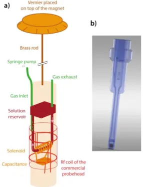
Figure 1. a) Schematic drawing of the WIFI-NMRS device. The
red parts correspond to the commercial probehead on which it is installed. b) 3D-rendering of the NMR insert.
In order to improve the coupling between the pickup coil and the sample without modifying the commercial probe-head, an inductively-coupled scheme can be used, where a resonator is used to shape the rf magnetic field lines, strengthening the irradiation field in the region of interest and, due to the reciprocity theorem,6 increasing the
sensi-tivity in this region. This solution is a very popular way to wirelessly transmit data or even energy with a high power efficiency,7 and has widely been used in MRI8–12 and in
solid-state NMR spectroscopy for the MACS ('Magic Angle Coil Spinning') approach.13 The methods for calculating and
im-proving the inductive coupling between two coils are also well documented.14–17
The idea here is to introduce the assembly containing the 3D-printed microfluidics, the NMR coil and the capacitance through the top of the NMR magnet, as would be the case for any liquid sample (Figure 1a). Outside the spectrometer the reservoir and the fluidic channels drawn in dark red in Fig. 1a are filled with the solution by using a normal micropi-pette, and are checked for stuck bubbles. Then a cap at-tached to a brass rod ended by a Vernier is plugged on the top of the NMR insert. The ensemble is introduced into the magnet bore. The Vernier leans on the top of the magnet, the length of the rod ensuring its perfect vertical positioning with respect to the commercial probehead. Angular posi-tioning of the micro-coil is achieved by manually turning the Vernier.
The solution flow inside the circuit is actuated via a pro-grammable syringe pump that pushes the carrier gas and sets the liquid in motion (see video in Supporting Infor-mation S1).3 Therefore a gas pipe (in green on Fig. 1a)
con-nects the solution circuit in its vertical part to the syringe. This pipe sits in a dedicated channel, visible on the top left of Fig. 1b, which allows for a reliable positioning of the noz-zle.
Except for the microcoil, the NMR insert, represented in Fig. 1b, is fully printed via a Polyjet printer (see Supp. Info.). A PMMA-like resin has been chosen for its magnetic suscepti-bility close to that of water and also because it is transpar-ent. Two pieces are printed: the upper part of the insert con-tains the reservoir and the fluidic channels; the lower part enables installation of the NMR resonator and closes the so-lution circuit. Most of the time the detection zone consists of a solenoid wound on a quartz tube. This element is mounted in a carefully designed groove on the 3D printed part, which ensures proper centering of the coil and capil-lary for each insert. The two pieces are then glued; the de-tection region is then sealed to improve the homogeneity of the magnetic field. The coil is finally tuned to the frequency of interest.
This device has been dubbed WIFI-NMRS, for 'Wireless In-ductive coupling & Flow for Increased NMR Sensitivity'. Fig-ure 1b gives a 3D-rendering of the NMR insert. It has the shape of an NMR tube with its spinner, in order to be easily positioned inside the probehead. Only the diameter of the lower part varies to be adjusted to the commercial probe-head (from 5 to 20 mm).
Optimization of the coupling between the two coils is made by manually adjusting the angular position of the insert
thanks to the Vernier. When this device is inserted in a com-mercial probe, two resonance dips appear on the wobble curve: one below and one above the original resonance fre-quency of the probehead, with the splitting between these dips being related to the angle between the two coils, as defined in Figure 2a. Using the probe capacitors enables one to match and tune either of these two. This allows one to reach a wide range of frequencies using a single-resonance commercial probehead.
The first series of tests were conducted to characterize the behavior of such an inductively-coupled system, inde-pendently from the fluidic circuit. In order to test the NMR signal intensity as a function of the angle , in a first step NMR experiments have been performed with the
WIFI-NMRS system installed on a 10-mm dual broadband/1H
probehead. The use of a fast-relaxing nucleus such as 23Na
allowed us to study various angular configurations in a rea-sonable time window. Figure 2b displays the intensity of the
23Na NMR signal, recorded on a saturated solution of NaCl,
as a function of the angle .
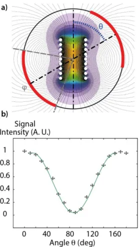
The data were then fitted using a simple cosine function, but it can be observed that the experimental curve is wider at its maxima than at its minima. This behavior is explained by the magnetic field distribution due to this finite-size sole-noid (see Fig. S2 of the Supp. Info.).
It can be seen that according to the angle a quasi-complete extinction of the signal can be obtained. Precisely, when equals 90° the obtained signal is only 4% of the maximum signal. This signal modulation has further been confirmed in 23Na MRI experiments with an 8-mm WIFI-NMRS insert
placed into a micro-imaging probehead, see Fig. S4 of the Supp. Info.
Figure 2. Principle of the WIFI-NMRS device. a) View along the
static magnetic field axis showing the angle θ between the two radiofrequency fields in interaction. The red lines correspond to the area inside the two loops of the saddle coil. The angle covered by these loops is named φ. The magnetic field repre-sented here ranges from 10-4 T (purple) to 1.8 10-3 T (orange)
for an excitation current of 1 Ampere. b) Intensity of the rec-orded 23Na NMR signal as a function of the angle θ between the
micro-coil axis and the commercial saddle coil of a dual broad-band/1H probe. The NMR probe was matched and tuned after
each change in angular position.
On these images taken with two different angular positions of the solenoidal coil with respect to the commercial saddle coil, it can be seen that when the two coils are misaligned ( = 100°) a lower signal intensity is observed. Particularly looking at the radial images, it can be remarked that the ex-tremities of the capillary are brighter than the central part, corresponding to the region of the microcoil. This is the con-trary when = 0°, emphasizing the effect of the inductive coupling between the two coils.
As previously stated, when the WIFI-NMRS device is in-serted, two dips appear on the wobble curve. This is due to the fact that the resulting circuit (which is made of two res-onant circuits: the WIFI-NMRS device and the commercial probe) possesses two poles. By soundly choosing the reso-nance frequency of the micro-resonator and that of the un-loaded commercial probe (with the tuning knobs on a broadband probe) both at the median value of the reso-nance frequencies of two nuclei separated by less than the difference created by the radiofrequency coupling, a dou-bly-tuned coil is obtained. As an example, Fig. 3 displays the wobble curve showing a system tuned to the 13C and 23Na
nuclei at 11.7 Tesla (125.7 and 132.3 MHz, respectively). This scheme allows to benefit from the sensitivity gain of the WIFI-NMRS device for two different channels, and for in-stance in the present case to perform a 23Na NMR image and
a 13C NMR spectrum without wiring change or further
ad-justment.
Figure 3. Example of signal reflected from the NMR probe (a
10-mm old generation BB probe) with an inductively-coupled insert aligned with a saddle coil. At 11.7 T, nuclei at two reso-nance frequencies can be studied with this setup: 13C (125.7
MHz) and 23Na (132.3 MHz). The NMR probe was originally
tuned to 129 MHz – median value between the resonance fre-quencies - before introduction of the WIFI-NMRS insert. For the purpose of testing not only the signal gain afforded by the NMR micro-detection system, but also the advantage presented by the controlled solution flow, in a second step NMR experiments have been performed with the
WIFI-NMRS system installed on a micro-imaging probehead
equipped with an 8-mm 13C-1H insert.
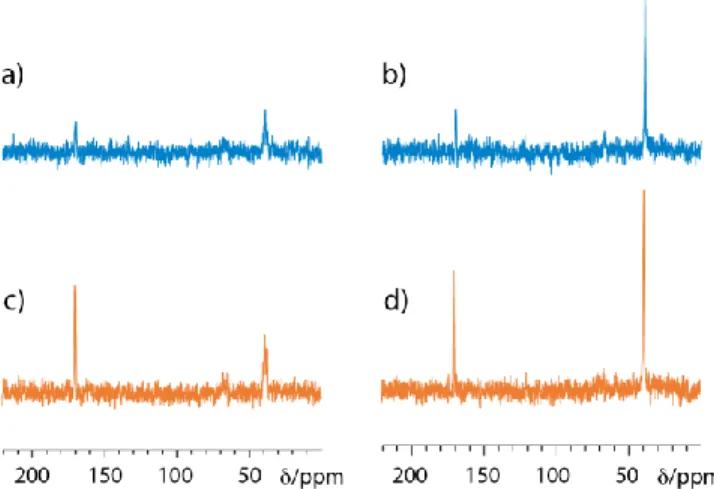
Figure 4. Data on the 10 mM 13C-urea sample. a) 13C NMR
spec-tra acquired in 18 minutes with the WIFI-NMRS system with an interscan delay of 1s, on a static solution and with a gas flow of 1 mL/min. b) Comparison of the signal-to-noise ratios (SNR) obtained with the same experimental parameters for the WIFI-NMRS system (static and flow modes) and classical detection in an 8-mm NMR tube inside the commercial probehead. c) Idem, but SNR corrected by the total solution volume. d) SNR cor-rected by the detected volume. Other details: see the Supp. Info.
Figure 4 displays the 13C NMR spectra obtained on a 10 mM 13C-enriched urea sample in 1024 scans separated by a
short delay of 1 s, without and with an air flow of 1 mL/min. The gain in signal-to-noise ratio between the flow and static modes is obvious in Fig. 4a, but Figs 4b-d enables one to compare the signal-to-noise ratios measured with the
WIFI-NMRS device without and with solution flow, and with a
classical (8-mm o.d.) NMR tube. In this purpose, the SNR val-ues corrected by (divided by) the total solution volume are given in Fig. 4b. A gain by a factor 4.6 is observed in favor of the flowing solution over the static sample case. The SNR is also 1.9 higher than with the classical NMR tube. Note that for the present tests, an insert with an 800-µL solution cir-cuit has been used, but this volume can be reduced to 300 µL in other versions (see Table S1). Considering the SNR corrected by the detection volume (Fig. 4d) further empha-sizes the advantage of the approach. So, when it is reported to the detected volume, the gain between the on-flow mode of the WIFI-NMRS system and the classical detection in an 8-mm tube reaches now 289.2. Thus, due to the high sensi-tivity afforded by the micro-solenoid (shape efficiency and filling factor) and the solution flow in a closed loop, this setup compares favorably with the classical detection in NMR tubes, both in terms of mass- and concentration-based sensitivity.
In Supporting Information (Fig. S5) the signal-to-noise ratio has been reported as a function of the rf pulse flip angle, for two different interscan delays (0.5 and 1 s) and a gas flow of 1 mL/min. While for a recycling delay of 1 s the apparent Ernst angle is near 90°, it falls to ca. 75° for a recycling delay of 0.5 s. This means that despite a longer solution loop com-pared to our previous work, the gas flow is still able to effi-ciently pump the liquid with a decent flowrate. The fact that the apparent Ernst angle is ca. 90° with a recycling delay of 1 s means that all the solution in the detection region has been replaced in this time frame, allowing to fully circum-vent relaxation. Since the detected volume in a 8 mm insert is 12.5 µL, we therefore can calculate the liquid flowrate which is 0.75 mL/min, for a gas flowrate of 1 mL/min. This value is coherent with our previous work, where the fluidic circuit was different but the principle was the same. 4
This low-cost inductive device enables one to keep all the capabilities of the host probehead, such as the use of other rf channels. As an example, 13C spectra have been recorded
on a sample of 15N-,13C-enriched glycine in D2O, with 1H
de-coupling (Figure 5). Recording the spectra in the presence of a solution flow and an interscan delay of 1 s provides a SNR gain of 1.4 for the signal of the CH2 group (1.3 when 1H
decoupling is applied), and of 3.4 for the signal of the CO group (2.9 when 1H decoupling is applied). Note that the
proton-carbon cross-relaxation comes to further enhance the signal and accelerate the apparent relaxation of 13C,
even (in a less extent) for the quaternary carbon. As ex-pected on the spectrum of Fig. 5c the integral values of the two signals are identical within 1.3%.
Whereas these results have been obtained on 10- and 8-mm probes, which allowed us to assemble the WIFI-NMRS de-vices using quartz capillaries in the detection region (see figure S6), we are currently developing 5mm devices which would be of greater interest since most of the liquid-NMR probes are made for tubes of this diameter. Since the use of glass capillaries was compromised for these devices, due to the small length available (2 mm) for the capillary, we had to turn to another manufacturing technique. We chose to print the capillary along with the rest of the microfluidic de-vice, therefore reducing the number of parts to be assem-bled. Using this technique, the printed parts already possess a complete fluidic circuit, while the coil still has to be wound around the capillary, which is made possible by designing an empty space around this printed capillary, which can later be filled with polymer, for susceptibility matching pur-poses.
Figure 5. 13C NMR spectra recorded in the same conditions
with the WIFI-NMRS device on a 25-mM sample of 15N-13
C-en-riched glycine in D2O, in static mode (a) and b)) and with a gas
flow of 1 mL/min (c) and d)). In b) and d) 1H decoupling was
applied during acquisition. An interscan delay of 1s was used for all these acquisitions. Other details: see the Supp. Info.
To study the sensitivity of these 5 mm WIFI-NMRS devices, we used one of these tuned for 13C with a sample of 200 mM 13C Urea in D2O. This device has been placed inside a 5 mm
Bruker TBI probe. The results obtained with this configura-tion are presented in figure S7. The wobble curve easily shows that despite the small size of the solenoid and the large distance to the saddle coil (since we are using the outer coil of the inverse probe) we are able to get a good splitting indicating a strong coupling between the two coils. These preliminary results show that these smaller systems are prone to show the same advantages as the 10- and 8- mm ones discussed in this article.
Other on-flow solutions have been proposed to monitor in real time chemical systems without modifying the NMR in-strument. For instance, Khajeh et al. developed an elegant and cheap solution involving a peristaltic pump outside the
NMR magnet.18 However the WIFI-NMRS system presented
here does not use large sample volumes: 300 – 800 µL in the presented versions, but that can further be reduced by de-creasing the diameter of the 3D-printed channels. Another advantage of this system is that this volume is concentrated inside the highest magnetic field region of the magnet, en-suring a reliable pre-polarization.
In addition to be inexpensive – the only components are the 3D-printed inserts, the brass rod equipped with a Vernier, the tubing for the gas inlet, and the syringe pump - and adaptable on every high field NMR spectrometer, the
WIFI-NMRS approach presents several advantages. i) The
con-trolled solution flow enables avoiding the relaxation rate constraint, ii) the solenoidal micro-coil presents optimal shape and filling factor, iii) even with a single mono-tuned microcoil, it is possible to perform heteronuclear experi-ments, according to the host probe (1H decoupling, X-1H
ex-periments), iv) the liquid flow can be used to transport hy-perpolarized species to the NMR detection area and there-fore increase the SNR.
Also, as the quality factor depends mostly of the host probe, the device will be very powerful when used in conjunction with cryoprobes.
ASSOCIATED CONTENT
Supporting Information
Video of the mini bubble pump in operation, wobble curve with the WIFI-NMRS insert, analysis of the magnetic flux from the solenoid insert through the probe, tuning of a Micro-5 probe using an additional capacitor, 23Na MRI images performed with
the WIFI-NMRS insert, detailed view of the 8-mm WIFI-NMRS insert, preliminary experiments with 5-mm inserts and exper-imental details. The Supporting Information is available free of charge on the ACS Publications website.
AUTHOR INFORMATION
Corresponding Author
* e-mail: [email protected]; Phone: +33 1 69084245.
ORCID
Guillaume Carret: 0000-0002-2083-3654 Patrick Berthault: 0000-0003-4008-2912
Notes
The authors declare no competing financial interests.
ACKNOWLEDGMENT
Support from the French Ministry of Research (project 17-LCV2-0002-01 LabCom DESIR) is acknowledged.
REFERENCES
(1) Laude, D. A.; Lee, R. W.; Wilkins, C. L. Analytical Applica-tions of a Recycled Flow Nuclear Magnetic Resonance Sys-tem: Signal Enhancement of Slowly Relaxing Nuclei. Anal.
Chem. 1985, 57 (7), 1281–1286.
(2) Fischer, H. H.; Seiler, M.; Ertl, T. S.; Eberhardinger, U.; Ber-tagnolli, H.; Schmitt-Willich, H.; Albert, K. Quantification Studies in Continuous-Flow 13C Nuclear Magnetic Reso-nance Spectroscopy by Use of Immobilized Paramagnetic Relaxation Agents. J. Phys. Chem. B 2003, 107 (20), 4879– 4886.
(3) Causier, A.; Carret, G.; Boutin, C.; Berthelot, T.; Berthault, P. 3D-Printed System Optimizing Dissolution of Hyperpolar-ized Gaseous Species for Micro-SHyperpolar-ized NMR. Lab. Chip
2015, 15 (9), 2049–2054.
(4) Carret, G.; Berthelot, T.; Berthault, P. Enhancing NMR of Nonrelaxing Species Using a Controlled Flow Motion and a Miniaturized Circuit. Anal. Chem. 2017, 89 (5), 2995– 3000.
(5) Doty, F. D. Probe Design and Construction. In eMagRes; John Wiley & Sons, Ltd, 2007.
(6) Hoult, D. I.; Richards, R. E. The Signal-to-Noise Ratio of the Nuclear Magnetic Resonance Experiment. J. Magn. Reson.
1976, 24, 71–85.
(7) Wei, X.; Wang, Z.; Dai, H. A Critical Review of Wireless Power Transfer via Strongly Coupled Magnetic Reso-nances. Energies 2014, 7 (7), 4316–4341.
(8) Wang, T.; Ciobanu, L.; Zhang, X.; Webb, A. Inductively Cou-pled RF Coil Design for Simultaneous Microimaging of Multiple Samples. Conc. Magn. Reson. B 2008, 33B (4), 236–243.
(9) Ginefri, J.-C.; Rubin, A.; Tatoulian, M.; Woytasik, M.; Bou-mezbeur, F.; Djemai, B.; Poirier-Quinot, M.; Lethimonnier, F.; Darrasse, L.; Dufour-Gergam, E. Implanted, Inductively-Coupled Radiofrequency Coils Fabricated on Flexible Pol-ymeric Material : Application to in Vivo Rat Brain MRI at 7T. J. Magn. Reson. 2012, 224, 61–70.
(10) Tang, J. A.; Jerschow, A. Practical Aspects of Liquid-State NMR with Inductively Coupled Solenoid Coils. Magn.
Re-son. Chem. 2010, 48 (10), 763–770.
(11) Utz, M.; Monazami, R. Nuclear Magnetic Resonance in Mi-crofluidic Environments Using Inductively Coupled Ra-diofrequency Resonators. J. Magn. Reson. 2009, 198 (1), 132–136.
(12) Ludwig, U.; Eisenbeiss, A.-K.; Scheifele, C.; Nelson, K.; Bock, M.; Hennig, J.; von Elverfeldt, D.; Herdt, O.; Flügge, T.; Hövener, J.-B. Dental MRI Using Wireless Intraoral Coils.
Sci. Rep. 2016, 6, 23301.
(13) Sakellariou, D.; Goff, G. L.; Jacquinot, J.-F. High-Resolution, High-Sensitivity NMR of Nanolitre Anisotropic Samples by Coil Spinning. Nature 2007, 447 (7145), 694.
(14) Mispelter, J.; Lupu, M.; Briguet, A. NMR Probeheads for
Bi-ophysical and Biomedical Experiments; Imperial College
Press, 2006; Vol. 1.
(15) Hoult, D. i.; Tomanek, B. Use of Mutually Inductive Cou-pling in Probe Design. Conc. Magn. Reson. 2002, 15 (4), 262–285.
(16) Jacquinot, J.-F.; Sakellariou, D. NMR Signal Detection Using Inductive Coupling: Applications to Rotating Microcoils.
Conc. Magn. Reson. Part A 2011, 38A (2), 33–51.
(17) Raad, A.; Darrasse, L. Optimization of NMR Receiver Band-width by Inductive Coupling. Magn. Reson. Imag. 1992, 10 (1), 55–65.
(18) Khajeh, M.; Bernstein, M. A.; Morris, G. A. A Simple Flowcell for Reaction Monitoring by NMR. Magn. Reson. Chem.