Analyzing the Wien Filters for the DANTE Ion
Accelerator
by
Carolena Ruprecht
Submitted to the Department of Nuclear Science and Engineering
in partial fulfillment of the requirements for the degree of
Bachelor of Science in Nuclear Science and Engineering
at the
MASSACHUSETTS INSTITUTE OF TECHNOLOGY
June 2016
c
Massachusetts Institute of Technology 2016. All rights reserved.
Author . . . .
Department of Nuclear Science and Engineering
May 18, 2016
Certified by . . . .
Dennis G. Whyte
Professor of Nuclear Science and Engineering
Thesis Supervisor
Accepted by . . . .
Michael P. Short
Assistant Professor of Nuclear Science and Engineering
NSE Committee for Undergraduate Students
Analyzing the Wien Filters for the DANTE Ion Accelerator
by
Carolena Ruprecht
Submitted to the Department of Nuclear Science and Engineering on May 18, 2016, in partial fulfillment of the
requirements for the degree of
Bachelor of Science in Nuclear Science and Engineering
Abstract
Materials used in nuclear reactors, both fission and fusion, are continuously interact-ing with high energy ions. Tandem electrostatic accelerators, such as DANTE, are able to produce ions at high energies that can be used to simulate these interactions. In order to enhance the quality of experimental data taken using an accelerator, it is useful to ensure that the particles being accelerated are of the same species. Wien filters use electromagnetic forces to filter particles in an ion beam. Also referred to as mass selectors or velocity selectors, Wien filters operate on the principles of the Lorentz force in order to select ions of a certain mass while filtering out all others. The Wien filters in DANTE were modeled and tested in order to determine their effectiveness and ideal operating conditions. Experimental data was taken by vary-ing the voltage applied to the Wien filters operatvary-ing in DANTE. Preliminary results concluded that the Wien filters are able to steer the beam, as demonstrated by the impact of Wien filter voltage on the beam current through the accelerator. However, the experiment was inconclusive as to whether or not the Wien filters successfully filtered out unwanted ions. The settings applied during the experiment were then simulated with a model. For a deuterium beam, the model recommends voltage set-tings of 312 V and 341 V for the horizontal and vertical Wien filters, respectively. The model results are consistent with the experimental data. Recommendations for future work on this project are outlined following the results.
Thesis Supervisor: Dennis G. Whyte
Acknowledgments
To Professor Dennis Whyte
I will be forever thankful for all the times you handed me a piece of chalk and told me to ”write it out on the board,” in typical MIT fashion. In doing so, you have helped me develop a deeper understanding and appreciation for nuclear science and engineering while strengthening the self confidence the Institute so often relentlessly challenges. Your enthusiasm for nuclear science has been contagious since day one of 22.01 and I hope to take it with me wherever I go.
To Professor Michael P. Short
One thing I have learned at MIT is that the most valuable thing in life is time. Regardless, you have never failed to make time to support me through my academic career at MIT. Whether it be making a schedule, choosing a UROP, discussing classes, or just getting my thoughts in order, your door has always been open. Words cannot express how grateful I am for your dedication to not only my education, but to that of the entire NSE undergraduate community.
To Brandon Sorbom
It has been an honor to have you as my UROP direct supervisor for the past two years. The practical knowledge I have gained through working with you in the lab has been invaluable and it will help me throughout my career. I am grateful for all of the times you stopped to explain various processes and concepts to me, and for your patience when I needed them explained a second or third time! I admire all of the hard work you have done and continue to do with DANTE and I wish you the best of luck as you continue to pursue your doctoral degree here at the PSFC.
To Leigh Ann Kesler
If you had a nickel for every silly question you have answered for me between 22.01 and working with DANTE, you might finally be able to get a ’Big Screen’ installed
down in the lab. In all seriousness, I am grateful for your willingness to help me better understand nuclear science and engineering throughout my time here. It has been a pleasure working with you in lab and I wish you all the best as you continue your academic endeavors here at MIT.
To Krista, Marty, Signe & James Ruprecht
Thank you for being my unwavering support system from day one. You have always believed in me, especially at times when I found it hard to believe in myself. I love you all and I thank you for all you have given me.
To Gabby and Vince
If I had to pick two people to spend four years in an orange-painted, 240f t2 room
with me, you guys would be at the top of my list. I am so thankful that you both were by my side through the many long hours of studying and psetting in the chateau. I could not have survived this place without you! I am looking forward to seeing all of the great things you both go on to do after graduation and I am sure that we will remain in touch throughout our careers.
Contents
1 Introduction 9
1.1 DANTE . . . 9
1.2 Analyzing Wien Filters for DANTE . . . 10
1.3 Wien Filters & Nuclear Data Collection . . . 11
2 Background 13 2.1 Accelerator Overview . . . 13
2.2 Electromagnetic Force . . . 15
2.3 Wien Filters . . . 16
2.4 Wien Filters in DANTE . . . 17
3 Methodology 21 3.1 Model . . . 21
3.1.1 Modeling the Electric Field . . . 21
3.1.2 Modeling the Magnetic Field . . . 22
3.1.3 Modeling Ion Trajectory due to Lorentz Force . . . 22
3.2 Experiment . . . 24
4 Results & Discussion 25 4.1 Model Results & Discussion . . . 25
4.2 Experimental Results & Discussion . . . 28
5 Conclusion & Future Work 31 5.1 Conclusion . . . 31 5.2 Future Work . . . 31
Chapter 1
Introduction
1.1
DANTE
Located at 150 Albany Street, Cambridge, MA, DANTE is used for research by the Plasma Science and Fusion Center (PSFC) at the Massachusetts Institute of Tech-nology. The tandem ion accelerator, DANTE, is able to accelerate low energy ions up to 4.1 MeV using a series of electrostatic fields. [4] In a tandem ion accelerator, negative ions are produced in the negative ion source and accelerated to low energies through two orthogonal particle filters and an Einsel lens (labeled ’Lens’ in Figure 1-1). Ions are then accelerated to high energy by the high voltage terminal, located at the region where the ’Foil Stripper’ is located in Figure 1-1. The foil stripper removes some electrons from the ions before they are accelerated through the high energy accelerating tube and steered towards a target station by an electromagnet.
In recent years, researchers within the PSFC have needed to repair or replace a few components within DANTE, before returning it to full operation in the spring of 2016. Two of the components needing repairs were the horizontal and vertical particle filter, Wien filters, and those repairs were a large part of this research project.
Figure 1-1: DANTE Tandem Accelerator [4]
1.2
Analyzing Wien Filters for DANTE
In the region of the accelerator labeled ’Beam Steering’ in Figure 1-1, there are elec-tromagnetic particle filters, known as Wien filters, designed to isolate an ion species within the beam. Wien filters use static electric and magnetic fields to filter ions by both their masses and energies. At the low energy end of the accelerator, all ions are accelerated to the same energy, therefore the Wien filters can select ions based on their masses. However, after the ions have been accelerated to the terminal voltage and pass through the stripping foil, they can have a variety of different charge states, and thus a variety of different energies. Therefore, the ions at the target end of the accelerator vary in both mass and energy making it difficult to filter ions.
By creating a mono-isotopic beam, the validity of data recorded at the high-energy end of the particle accelerator is improved. In the summer of 2014, the horizontal Wien filter received minor repairs and the vertical Wien filter was rebuilt. The goal of this analysis is to determine the effectiveness of the recently repaired particle filters by sweeping through the filter voltage range and observing the output beam current. Furthermore, the expected behavior of the Wien filters will be modeled using fundamental physics principles. The results of this analysis will improve operation of the Wien filters, as well as overall understanding of the behavior of DANTE.
1.3
Wien Filters & Nuclear Data Collection
Nuclear reactions typically create high energy ions that interact with matter in a variety of ways. Nuclear scientists and engineers are continuously researching to de-velop a better understanding of these interactions in order to design safe and durable systems that successfully convert nuclear power into electricity. Accelerators, such as DANTE, produce high energy ions for a variety of applications, such as gathering data of ion interactions with different materials.
One of the fundamental data sets needed for the development of nuclear science and engineering is nuclear cross section data. A nuclear cross section is the probability that a given particle, at a specific energy, will cause a given nuclear reaction. For example, the nuclear fission cross section of U-235 is relatively high at low energies, therefore low energy neutrons have a high probability of being absorbed by U-235 to cause a fission. Particle accelerators allow cross section data to be taken at energy levels equal or similar to those created by nuclear reactions. In order for the cross section data to be as accurate as possible, the ions within the beam need to all be the same species. However, many different ions are created at the source of an accel-erator and can end up in the beam, reducing the accuracy of the resulting data. The Wien filters improve the validity of the data by guiding one species of ion through the accelerator and filtering out all other ion species. Not only is the validity of cross section data improved by Wien filters, but also the validity of data taken for a variety of other applications.
Chapter 2
Background
2.1
Accelerator Overview
The tandem two-phase accelerator, DANTE, is located in an MIT laboratory on Al-bany Street, Cambridge, MA. Through its length of 4.5 m, DANTE accelerates an ion beam with up to 4mA of current to energies as high as 4.1 MeV.[4] Ions are created in a low pressure chamber (10−7− 10−8 torr [4]), referred to as the source, at the low
energy end of DANTE. The first phase starts within the source, where electricity is run through a tungsten (W) filament, heating it up so that it will release electrons (e−) with very little energy. The electrons are then accelerated to 100 eV within the plasma chamber. [4]
These electrons mainly interact with hydrogen or deuterium in order to form neg-atively charged ions. Eqn. 2.1 through 2.4 reflect the interactions occurring within the source. The negative ions are accelerated to 3 keV within the source, and an extraction electrode allows the ions to escape while keeping the electrons inside the chamber.[4] After exiting the source, the ions are accelerated further through two-orthogonal Wien filters before passing through an Einsel lens. The bias of the Einsel lens is controlled by the accelerator operator and is typically on the order of 5-10 kV. This bias is directly related to the energy the ions will have as they pass through the Wien filters. Next the ions are accelerated to the terminal voltage. Some electrons are
Figure 2-1: DANTE Ion Source[4]
then removed from the negatively charged ions by a stripping foil, creating a beam of positively charged ions that are accelerated through the second half of the accelerator.
H2∗+ (e−) → H−+ H (2.1) H3∗+ e− → H−+ H2 (2.2) D2+ (e−)∗ → D∗2+ e − (2.3) D2∗+ e−→ D−+ D (2.4)
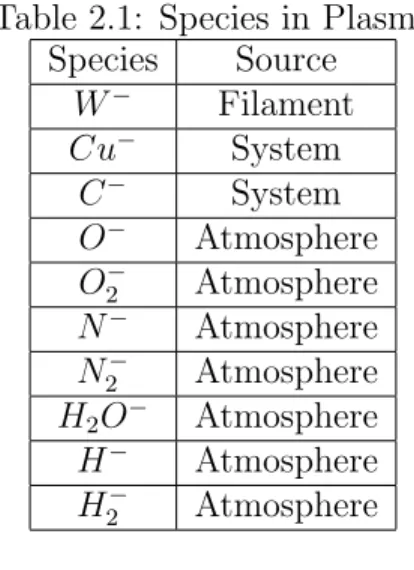
Ideally, a beam of only protons or deuterons is created in the source chamber. However, other species of ions can sometimes make it into the beam as the vacuum is not perfect and the source chamber contains ions other than hydrogenic ions. There-fore, particle filters are required to create a mono-isotopic beam through the tandem accelerator. Various ions within the source are listed in Table 2.1.
Table 2.1: Species in Plasma Species Source W− Filament Cu− System C− System O− Atmosphere O2− Atmosphere N− Atmosphere N2− Atmosphere H2O− Atmosphere H− Atmosphere H2− Atmosphere
2.2
Electromagnetic Force
Both electric and magnetic fields apply force to charged particles, such as ions in a particle accelerator. An electric field is defined by its force per unit charge and it acts along electric field lines. Electric fields apply a force to any charged particle. For a permanent magnet, magnetic field lines are drawn from the north end of a magnet to the south end. As two oppositely charged magnets approach each other, magnetic field lines are created along the axis of approach, as depicted in Figure 2-2. Magnetic fields apply a force to any charged particle with non-zero velocity perpendicular to the magnetic field.
Electric and magnetic fields are two aspects of an overarching branch of physics, electromagnetism. Electromagnetism is the study of the physical interactions between electric and magnetic forces. Electromagnetic force, also referred to as the Lorentz force, is function of charge (q), velocity (−→v ), electric field(−→E ), and magnetic field (−→B ), shown in Equation 2.5.
FLorentz = q[
− →
Figure 2-2: Magnetic Field Lines Produced by Permanent Magnets [1]
2.3
Wien Filters
Wien filters use electromagnetic force to deflect unwanted particles from an ion beam traveling towards the high-voltage terminal in a tandem accelerator. In a tandem par-ticle accelerator, all charged parpar-ticles are subject to the same voltage (V) potentials, and therefore raised to an energy (E) depending on their charge state (q).
E = V q (2.6)
At the low energy end of the accelerator, all ions are of the same charge state, -1, and thus at the same energy. However, because ions of different species differ in mass (m), the particles in the ion beam will be traveling at different velocities, as supported by the kinetic energy formula, Eqn. 2.7.
Ekinetic =
1 2mv
2 (2.7)
For this reason, Wien filters can be referred to as mass selectors or velocity se-lectors. By altering the electric field in the filter, the net Lorentz force on the ion beam is changed. The purpose of the Wien filter is to have a net zero force on the ions wanted in the beam so that they pass through the filter, and therefore a non zero force on all other particles so that they do not pass through. With zero voltage applied to the Wien filters, the electric field is zero and ions are purely affected by the magnetic field. The force applied to the ions due to the magnetic field is relatively stronger for light ions than for more massive ions at fixed energies. Therefore, when an electric field is applied in the Wien filters such that it counteracts the magnetic field, the resulting force on heavier ions is greater than it is on lighter ions, such as hydrogen and deuterium ions.
The Wien filters are able to filter ions of equal energy and different mass. It is important that they be located at the low energy end of a tandem accelerator so that all ions in the ion beam are at the same energy. At the high energy end of the accelerator, ions have passed through a stripping foil and are thus at different charge states and energies. It would be very difficult to filter ions that vary in both energy and mass at the high energy end of the tandem accelerator, where the only practical steering method is a strong magnet.
2.4
Wien Filters in DANTE
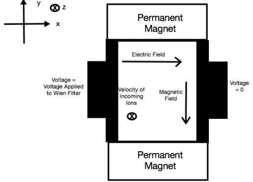
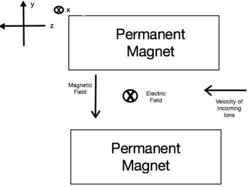
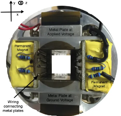
There were originally two Wien filters built for DANTE and in summer 2014, the vertical Wien filter was rebuilt and minor repairs were done to the horizontal Wien filter. Both Wien filters are of similar design, however they are oriented orthogonally with respect to each other. For reference, Figures 2-3 and 2-4 display relevant aspects of the Wien filter system. The coordinate convention in these schematics will be
referred to throughout the text. The electric field is created between two metal plates, filled in black in Figure 2-3. The magnetic field is created between two permanent magnets with opposite poles oriented inwardly.
Figure 2-3: Schematic of Horizontal Particle Filter
The horizontal Wien filter, built by Newton Scientific Instruments (NSI) in Cam-bridge, MA, has 5 wires, with 910 kΩ resistors, spaced 2.7 mm apart that run along each magnet in the z direction. These wires and resistors form a circuit designed to minimize current in order to create a static electric field between the two metal plates. The horizontal Wien filter deflects ions in the x direction. The vertical Wien filter has 4 wires spaced 3.5 mm apart as shown in Figure 2-5. The vertical Wien filter, shown in Figure 2-5, deflects particles in the y direction. The magnetic field magnitude along the z axis of both particle filters is shown in Table 2.2. The filters have a 14x14 mm opening and are both 50 mm along the z axis.
Figure 2-4: Schematic of Horizontal Particle Filter
Table 2.2: Magnetic Field of Wien Filters in DANTE Magnetic Field of Horizontal Filter along Z axis d (cm) −→B (Gauss) 0.0 90 0.5 140 1.0 180 1.5 260 2.0 280 2.5 310 3.0 330 3.5 320 4.0 290 4.5 260 5.0 220 Magnetic Field of Vertical Filter along Z axis d (cm) −→B (Gauss) 0.0 125 0.5 240 1.0 290 1.5 310 2.0 330 2.5 345 3.0 330 3.5 290 4.0 260 4.5 230 5.0 140
Chapter 3
Methodology
3.1
Model
All modeling was done in Matlab, with the file included in the Appendix. The model can be used to estimate optimal Wien filter voltages for any ion, though the analysis will focus on deuterium, hydrogen, and oxygen ions. For the purposes of this model, the following assumptions have been made:
1. Fringe effects due to both electric and magnetic fields are negligible.
2. Every ion entering the Wien filters has an initial velocity purely in the z direction. 3. Every ion entering the Wien filters enters through the center of the filter, therefore the original position along the x and y axes is zero.
3.1.1
Modeling the Electric Field
Ideally, a Wien filter has two charged plates that create an electric field orthogonal to the magnetic field. [3] In this case, there are a set of parallel wires along each magnet in the Wien filters that create potential drops, inducing an electric field parallel to the magnetic field in each filter. For the purposes of this model, the electric field is assumed to be constant and directly related to the applied voltage and the width of the Wien filter.
This assumption requires that the electric field generated by the current in the parallel wires be negligible. The model will compare the electric field generated by the current to the overall electric field induced by the wire configuration. Each current carrying wire segment running along the z axis in the Wien filters generates an electric field in the radial direction, with respect to the wire. However, the circuit is designed with high resistance in order to generate very little current, and thus minimal fringe magnetic fields. The electric fields of each wire segment (10 wire segments in the horizontal filter, 8 in the vertical) act on ions traveling through the Wien filters. The electric field, −→E , of each wire can be modeled by Equation 3.1 [2], where r is the distance from the center line of the wire, R is the resistance in the wire segment, I is the current through the wire, δV is the potential drop across the wire segment, l is the length of the wire segment, and a is the radius of the wire.
− → E (r) = RI + 2δV 2ln(al) ˆ r r (3.1)
3.1.2
Modeling the Magnetic Field
For simplicity, the magnetic field in each filter is modeled as constant for each region measured in Table 2.2. The component of the Lorentz force due to the magnetic field is calculated for each region in the filters and applies for the amount of time it takes the ion to travel through each region.
3.1.3
Modeling Ion Trajectory due to Lorentz Force
The electric component and the magnetic component of the Lorentz force are act-ing in opposact-ing directions. The Lorentz force (Equation 2.5) acts on ions travelact-ing through the Wien filters and accelerates them towards the walls of the filters. Ideally, only one species of ion will experience very little Lorentz force such that it does not collide with the walls of the filters. All other ion species should experience enough
Lorentz force to make contact with the wall, thus being removed from the beam.
The trajectory of the ions traveling through the Wien filters can be derived from Newton’s 2nd Law, Equation 3.2, where −→F is the Lorentz force, m is the mass of the ion, and −→a is the acceleration of the ion. As −→F and m are known, −→a can be calculated and integrated twice to produce Equation 3.3, where t is the amount of time the force is applied and x is the distance traveled by the ion. The acceleration is assumed to be purely in either the x or y direction, depending on whether it is the horizontal or vertical Wien filter. The amount of time the force is applied, t, is calculated using the velocity of the ion in the z direction and the distance traveled in the z direction. If x is greater than or equal to the original distance between the ion and the walls of the Wien filters, then the ion is no longer in the beam. If x is less than that distance, the ion will remain within the beam.
− → F = m−→a (3.2) x(t) = at 2 2 (3.3)
After exiting the Wien filters, the ions will approach an opening into the next phase of the accelerator that is 20 cm away and 1 mm in diameter. As they are continuing on the trajectories imposed by the Wien filters, it is possible that they will collide with a component of the accelerator instead of continuing on through the opening. The model also determines the horizontal and vertical displacement that ions will travel by the time they reach the opening. If the displacement is wider than that of the opening, the ions will be filtered from the beam.
3.2
Experiment
DANTE was pumped down to vacuum levels approximately 24 hours prior to oper-ation. For approximately 30 minutes, the terminal voltage was raised incrementally until reaching 0.5 MV. For reference, the operation settings are listed in Table 3.1.
Table 3.1: Operation Settings for 13APR2016 Filament Voltage 7.7 V
Filament Current 170 A Extraction 1.23 kV 3.32 mA
Focus 1.52 kV 0.01 mA Acceleration 8.14 kV 0.01 mA
The first objective was to confirm that the beam was deuterium. At the target station, the beam interacts with a layer of quartz glass. If the beam is deuterium, it will interact with the oxygen in the glass, resulting in the release of 871 keV gamma particles [5]. A NaI detector was set to collect gamma particles at the target station, distinguishing the particles by their various energies.
After confirming that the beam is deuterium, the experiment was designed to de-termine the effectiveness of the Wien filters. As the magnetic field inside the Wien filters is fixed, the electric field inside the filters was varied throughout the experi-ment. By adjusting the voltage across the wires in the filter, the magnitude of the electric field inside the filters changed. The control data was taken initially as the beam current with both Wien filters off. The voltage across the horizontal Wien filter was then varied in increments of 25 V from 25 to 300 V, with beam current results recorded at each increment. Next, the horizontal filter was returned to 0 V and the vertical filter was varied in increments of 25 V from 25 to 300 V, with beam current results recorded at each increment. Both Wien filters were then varied together in increments of 25 V from 25 to 300 V, with beam current results recorded at each increment.
Chapter 4
Results & Discussion
4.1
Model Results & Discussion
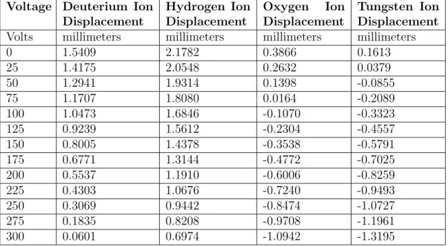
The expected horizontal and vertical displacements of D−, H−, O2−, W−. as a func-tion of the voltage applied to the Wien filters are listed in Table 4.1 and Table 4.2. In all cases, the displacement due to the Lorentz force is relatively small compared to the width of the Wien filters.
The ions continue on the trajectory induced by the Wien filters before reaching a 1 cm opening to the next phase of the accelerator, 20 cm away. Tables 4.3 and 4.4 display the resulting displacement at the opening. While the Wien filters are oper-ating to minimize the Lorentz force on deuterium ions, the resulting displacement of the other ions modelled is on the order of 1mm. Although this is smaller than the 5mm half width of the opening, many ions that did not enter the Wien filters along the center line will be filtered out of the ion beam as they will not make it through the opening to the next phase of the accelerator.
In order to minimize the Lorentz force on deuterium ions in the beam, the model concluded that the horizontal Wien filter should be set to 312 V and the vertical Wien filter should be set to 341 V, given that the Einsel lens is biased to 8140 V.
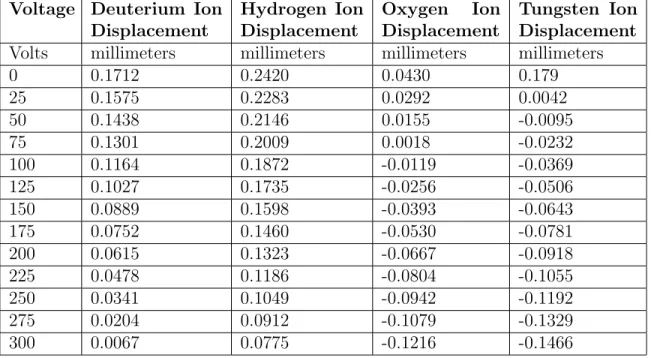
Table 4.1: Horizontal Wien Filter Voltage and Calculated Ion Displacement at End of Wien Filters
Voltage Deuterium Ion Displacement Hydrogen Ion Displacement Oxygen Ion Displacement Tungsten Ion Displacement Volts millimeters millimeters millimeters millimeters
0 0.1712 0.2420 0.0430 0.179 25 0.1575 0.2283 0.0292 0.0042 50 0.1438 0.2146 0.0155 -0.0095 75 0.1301 0.2009 0.0018 -0.0232 100 0.1164 0.1872 -0.0119 -0.0369 125 0.1027 0.1735 -0.0256 -0.0506 150 0.0889 0.1598 -0.0393 -0.0643 175 0.0752 0.1460 -0.0530 -0.0781 200 0.0615 0.1323 -0.0667 -0.0918 225 0.0478 0.1186 -0.0804 -0.1055 250 0.0341 0.1049 -0.0942 -0.1192 275 0.0204 0.0912 -0.1079 -0.1329 300 0.0067 0.0775 -0.1216 -0.1466
Table 4.2: Vertical Wien Filter Voltage and Calculated Ion Displacement at End of Wien Filters
Voltage Deuterium Ion Displacement Hydrogen Ion Displacement Oxygen Ion Displacement Tungsten Ion Displacement Volts millimeters millimeters millimeters millimeters
0 0.1870 0.2643 0.0469 0.0196 25 0.1733 0.2506 0.0332 0.0059 50 0.1596 0.2369 0.0195 -0.0079 75 0.1458 0.2232 0.0058 -0.0216 100 0.1321 0.2095 -0.0079 -0.0353 125 0.1184 0.1958 -0.0216 -0.0490 150 0.1047 0.1820 -0.0354 -0.0627 175 0.0910 0.1683 -0.0491 -0.0764 200 0.0773 0.1546 -0.0628 -0.0901 225 0.0636 0.1409 -0.0765 -0.1038 250 0.0499 0.1272 -0.0902 -0.1175 275 0.0362 0.1135 -0.1039 -0.1312 300 0.0224 0.0998 -0.1176 -0.1450
Under these conditions, deuterium ions will be displaced by approximately 9.0*10−4 mm in the x direction and -3.6*10−4 mm in the y direction. Meanwhile, hydrogen
Table 4.3: Horizontal Wien Filter Voltage and Calculated Ion Displacement at Open-ing to Next Phase of Accelerator
Voltage Deuterium Ion Displacement Hydrogen Ion Displacement Oxygen Ion Displacement Tungsten Ion Displacement Volts millimeters millimeters millimeters millimeters
0 1.5409 2.1782 0.3866 0.1613 25 1.4175 2.0548 0.2632 0.0379 50 1.2941 1.9314 0.1398 -0.0855 75 1.1707 1.8080 0.0164 -0.2089 100 1.0473 1.6846 -0.1070 -0.3323 125 0.9239 1.5612 -0.2304 -0.4557 150 0.8005 1.4378 -0.3538 -0.5791 175 0.6771 1.3144 -0.4772 -0.7025 200 0.5537 1.1910 -0.6006 -0.8259 225 0.4303 1.0676 -0.7240 -0.9493 250 0.3069 0.9442 -0.8474 -1.0727 275 0.1835 0.8208 -0.9708 -1.1961 300 0.0601 0.6974 -1.0942 -1.3195
Table 4.4: Vertical Wien Filter Voltage and Calculated Ion Displacement at Opening to Next Phase of Accelerator
Voltage Deuterium Ion Displacement Hydrogen Ion Displacement Oxygen Ion Displacement Tungsten Ion Displacement Volts millimeters millimeters millimeters millimeters
0 1.6828 2.3788 0.4222 0.1761 25 1.5594 2.2554 0.2988 0.0527 50 1.4360 2.1320 0.1754 -0.0707 75 1.3126 2.0086 0.0520 -0.1941 100 1.1892 1.8852 -0.0714 -0.3175 125 1.0658 1.7618 -0.1948 -0.4409 150 0.9424 1.6384 -0.3182 -0.5642 175 0.8190 1.5150 -0.4416 -0.6876 200 0.6965 1.3916 -0.5650 -0.8110 225 0.5722 1.2682 -0.6884 -0.9344 250 0.4488 1.1448 -0.8118 -1.0578 275 0.3254 1.0214 -0.9352 -1.1812 300 0.2020 0.8980 -1.0586 -1.3046
ions will be displaced about 0.6 mm in both directions, oxygen ions will be displaced about -1.3 mm in both directions, and tungsten ions will be displaced about -1.4 mm
in both directions. Considering the opening to the next phase of the accelerator is 10 mm in diameter, it is possible that ions entering the Wien filters near its edges may be filtered from the ion beam. However, the displacements are relatively small compared to the width of the opening and therefore may not be enough to successfully filter ions from the beam.
4.2
Experimental Results & Discussion
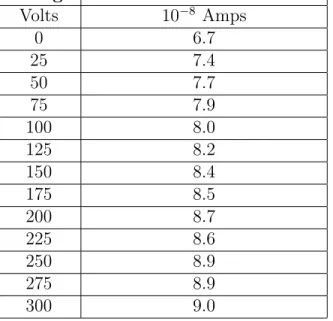
The data from the NaI detector at the terminal displayed a clear peak at 871 keV, verifying that the beam was deuterium. Therefore, the results reflect the effect of the Wien filters on a beam consisting of mostly deuterium ions, along with other ions listed in Table 2.1. The results of the three part experiment with the Wien filters are shown in Tables 4.5, 4.6, and 4.7. A Faraday cup was used to measure beam current at the target end of the accelerator.
Table 4.5: Horizontal Wien Filter Voltage and Deuterium Beam Current Voltage Deuterium Beam Current
Volts 10−8 Amps 0 6.7 25 7.4 50 7.7 75 7.9 100 8.0 125 8.2 150 8.4 175 8.5 200 8.7 225 8.6 250 8.9 275 8.9 300 9.0
The horizontal Wien filter data, in Table 4.5, shows a positive correlation between voltage and beam current. The beam current increased by roughly 34% as the voltage
was raised from 0 to 300 V.
Table 4.6: Vertical Wien Filter Voltage and Deuterium Beam Current Voltage Deuterium Beam Current
Volts 10−8 Amps 0 6.7 25 7.3 50 8.4 75 9.4 100 9.8 125 10.1 150 10.3 175 10.6
The vertical Wien filter data, in Table 4.6, shows a positive correlation between voltage and beam current. The beam current increased by nearly 60% as the voltage was raised from 0 to 175 V.
Table 4.7: Both Wien Filter Voltages and Deuterium Beam Current Horizontal Voltage Vertical Voltage Deuterium Beam Current
Volts Volts 10−8 Amps
0 0 6.7 25 25 6.5 50 50 8.1 75 75 9.5 100 100 10.4 125 125 10.7 150 150 11.0 175 175 11.3 200 175 11.8 225 175 11.4 250 175 11.5 275 175 11.5 300 175 11.9
As suspected from the first two phases of the experiment, the data collected with both Wien filters operational, in Table 4.7, shows a clear positive correlation between
voltage and beam current. With an increase of nearly 78% beam current, it is clear that the Wien filters had a significant effect on the ion beam.
Operating the Wien filters positively affected the beam current. However, the results to not conclude a clear optimal voltage for either Wien filter. According to the basic physics principles used in the model, varying the voltage should at first increase the deuterium beam current before reaching a maximum and then decrease the deuterium beam current.This is because the magnetic field deflects the beam and applying a voltage to the Wien filters creates an electric field that steers the beam in the opposite direction. More data needs to be taken while operating the Wien filters at higher voltages and while monitoring the beam species at the terminal. Furthermore, the data for the vertical Wien filter appeared better than that of the horizontal Wien filter until it stopped responding after 175 V. Further analysis of the vertical Wien filter need be done to determine the reason for this operational failure.
4.3
Comparing the Model to the Experimental
Re-sults
Although the experimental results are somewhat incomplete, they do agree with the trend and predictions made by the model. The model predicts that the optimal horizontal and vertical voltages are 312 V and 341 V, respectively. In the experiment, it was observed that the deuterium beam was being guided by the Wien filters, with increasing beam current as voltage approached 300 V. This trend reflects the results produced by the model.
Chapter 5
Conclusion & Future Work
5.1
Conclusion
The model predicts that the horizontal Wien filter should be operated at 312 V and the vertical Wien filter should be operated at 341 V in order to best filter out ions other than deuterium. The model can be applied more generally to any ion species. The experimental data indicates that the Wien filters significantly improve the beam current by steering the beam in voltage ranges consistent with the model predictions. There is not yet a clear indication as to whether the Wien filters actually filter the beam. For now, the horizontal and vertical Wien filters can be operated to increase the beam current at 300 V and 175 V, respectively. Further experimentation and analysis should be done before increasing the voltages on either.
5.2
Future Work
In order to better understand the Wien filters and the overall behavior of DANTE, more research and analysis must be done. The model could be improved by account-ing for fraccount-inge effects due to the electric and magnetic field, as they are potentially non-negligible. A next step for Wien filter updates would be to remove the vertical Wien filter and determine why it would not exceed 175 V. It would also be useful to know the maximum voltage each Wien filter could safely operate at.
Determining the purity of the ion beam with and without the Wien filters installed will be important to future understanding of their effects. This will be difficult as the transmitted current in DANTE, and accelerators in general, is highly variable and difficult to precisely reproduce, especially given continuous updates to the system. A recommendation for future deuterium beam experiments would be to have the NaI detector gathering data at different Wien filter settings for set time intervals. A spectroscopy analysis could be done to determine optimal Wien filter settings.
Appendix A
Matlab Code
%VARIABLES DEFINED BY EXPERIMENT - CHANGE THESE TO REFLECT EXPERIMENTAL CONDITIONS
E_eV = 8140.0 ; %Energy of ions at Wien filters - defined by Einsel Lens bias
V_horizontal = 312.0 ; %voltage setting of horizontal Wien filter
V_vertical = 341.0 ; %voltage setting of vertical Wien filter
%HORIZONTAL WIEN FILTER PARAMETERS R = 900000 ; % resistors in filters wire_radius = .0005 ; wire_area = pi*wire_radius^2 ; wire_length_segment = 0.05 ; half_width = 0.007 ; B_step = 0.005 ; gap_H = 0.0027 ; B_field_horizontal = [90; 140; 180; 260; 280; 310; 330; 320; 290; 260; 220]*10^(-4) ;
d_opening = 0.02 ; %distance from end if Wien filters to opening to next phase of accelerator %VERTICAL WIEN FILTER PARAMETERS
gap_V = 0.0035 ;
B_field_vertical = [125; 240; 290; 310; 330; 345; 330; 290; 260; 230; 140]*10^(-4) ;
%VARIBLES DEFINED BY THE UNIVERSE
m_D_amu = 2.014102; %deuterium mass in amu m_H_amu = 1.007947; %hydrogen mass in amu m_O2_amu = 32.0; %oxygen mass in amu m_W_amu = 183.84; %Tungsten mass in amu m_D_kg=m_D_amu*1.6605389*10^(-27);
m_H_kg=m_H_amu*1.6605389*10^(-27); m_O2_kg=m_O2_amu*1.6605389*10^(-27); m_W_kg = m_W_amu*1.6605389*10^(-27);
m_electron_kg = 9.10938356*10^(-31);
E_J = E_eV*1.60219*10^(-19); %convert eV to J e = 1.60217662*10^(-19) ; %electron charge in J epsilon0 = 8.854*10^(-12) ; %farads per meter rho = 1.68*10^(-8); %resistivity of copper %ION VELOCITY CALCULATED
v_D = sqrt(2*E_J/m_D_kg) ; v_H = sqrt(2*E_J/m_H_kg) ; v_O2 = sqrt(2*E_J/m_O2_kg); v_W = sqrt(2*E_J/m_W_kg);
%ELECTRIC FIELD INDUCED BY CURRENT CARRYING WIRES HORIZONTAL R_segment = rho*wire_length_segment/wire_area ; I_horizontal = V_horizontal/(6*R+7*R_segment) ; deltaV_segment_H = I_horizontal*R_segment ; sigma_B_H = epsilon0*(R_segment*I_horizontal+2*deltaV_segment_H )/(2*wire_radius*log(wire_length_segment/wire_radiu s)) ; EH1 = (wire_radius*sigma_B_H/epsilon0)/half_width ; EH2 = (wire_radius*sigma_B_H/epsilon0)/sqrt(gap_H^2+half_ width^2) ; EH3 = (wire_radius*sigma_B_H/epsilon0)/sqrt((2*gap_H)^2+h alf_width^2) ;
E_field_horizontal_current = (2*EH1 + 4*EH2 + 4*EH3)*(-1) ;
%ELECTRIC FIELD INDUCED BY CURRENT CARRYING WIRES VERTICAL I_vertical = V_vertical/(5*R+6*R_segment) ; deltaV_segment_V = I_vertical*R_segment ; sigma_B_V = epsilon0*(R_segment*I_vertical+2*deltaV_segment_V)/ (2*wire_radius*log(wire_length_segment/wire_radius)
) ; EV1 = (wire_radius*sigma_B_V/epsilon0)/sqrt((gap_V/2)^2+h alf_width^2) ; EV2 = (wire_radius*sigma_B_V/epsilon0)/sqrt((1.5*gap_V)^2 +half_width^2) ;
E_field_vertical_current = (4*EV1 + 4*EV2)*(-1) ; %ELECTRIC FIELD HORIZONTAL WIEN FILTER
E_field_horizontal = V_horizontal/(2*half_width)*(-1) ;
%ELECTRIC FIELD VERTICAL WIEN FILTER
E_field_vertical = V_vertical/(2*half_width)*(-1) ; %LORENTZ FORCE CALCULATION
F_net_D_horizontal = zeros(10,1); for n = 1:10 B = (B_field_horizontal(n)+ B_field_horizontal(n+1))/2.0 ; F_net_D_horizontal(n) = e*(E_field_horizontal + v_D*B) ; end F_net_D_vertical = zeros(10,1); for n = 1:10 B = (B_field_vertical(n)+ B_field_vertical(n+1))/2.0 ; F_net_D_vertical(n) = e*(E_field_vertical + v_D*B) ; end F_net_H_horizontal = zeros(10,1); for n = 1:10
B = (B_field_horizontal(n)+ B_field_horizontal(n+1))/2.0 ; F_net_H_horizontal(n) = e*(E_field_horizontal + v_H*B) ; end F_net_H_vertical = zeros(10,1); for n = 1:10 B = (B_field_vertical(n)+ B_field_vertical(n+1))/2.0 ; F_net_H_vertical(n) = e*(E_field_vertical + v_H*B) ; end F_net_O2_horizontal = zeros(10,1); for n = 1:10 B = (B_field_horizontal(n)+ B_field_horizontal(n+1))/2.0 ; F_net_O2_horizontal(n) = e*(E_field_horizontal + v_O2*B) ; end F_net_O2_vertical = zeros(10,1); for n = 1:10 B = (B_field_vertical(n)+ B_field_vertical(n+1))/2.0 ; F_net_O2_vertical(n) = e*(E_field_vertical + v_O2*B) ; end F_net_W_horizontal = zeros(10,1); for n = 1:10 B = (B_field_horizontal(n)+ B_field_horizontal(n+1))/2.0 ; F_net_W_horizontal(n) = e*(E_field_horizontal + v_W*B) ; end F_net_W_vertical = zeros(10,1);
for n = 1:10 B = (B_field_vertical(n)+ B_field_vertical(n+1))/2.0 ; F_net_W_vertical(n) = e*(E_field_vertical + v_W*B) ; end %ACCELERATION CALCULATION a_D_horizontal = zeros(10,1); for n = 1:10 a_D_horizontal(n) = F_net_D_horizontal(n)/m_D_kg ; end a_D_vertical = zeros(10,1); for n = 1:10 a_D_vertical(n) = F_net_D_vertical(n)/m_D_kg ; end a_H_horizontal = zeros(10,1); for n = 1:10 a_H_horizontal(n) = F_net_H_horizontal(n)/m_H_kg ; end a_H_vertical = zeros(10,1); for n = 1:10 a_H_vertical(n) = F_net_H_vertical(n)/m_H_kg ; end a_O2_horizontal = zeros(10,1); for n = 1:10 a_O2_horizontal(n) = F_net_O2_horizontal(n)/m_O2_kg ; end
a_O2_vertical = zeros(10,1); for n = 1:10 a_O2_vertical(n) = F_net_O2_vertical(n)/m_O2_kg ; end a_W_horizontal = zeros(10,1); for n = 1:10 a_W_horizontal(n) = F_net_W_horizontal(n)/m_W_kg ; end a_W_vertical = zeros(10,1); for n = 1:10 a_W_vertical(n) = F_net_W_vertical(n)/m_W_kg ; end
%DEFLECTION DISTANCE CALCULATION FOR DEUTERIUM ION travel_time_D =B_step/v_D; x_D_horizontal = a_D_horizontal*(travel_time_D^2)/2; total_x_D_horizontal = sum(x_D_horizontal) ; x_D_vertical = a_D_vertical*(travel_time_D^2)/2; total_x_D_vertical = sum(x_D_vertical) ; D_displacement_in_the_horizontal_direction_in_mm = total_x_D_horizontal*1000 ; D_displacement_in_the_vertical_direction_in_mm = total_x_D_vertical*1000 ; t2_D = d_opening/v_D; vf_D_H = (a_D_horizontal*travel_time_D); vf_D_H_total = sum(vf_D_H); x_D_H_opening = vf_D_H_total*t2_D + total_x_D_horizontal ;
vf_D_V = (a_D_vertical*travel_time_D); vf_D_V_total = sum(vf_D_V);
x_D_V_opening = vf_D_V_total*t2_D + total_x_D_vertical ;
D_displacement_in_the_horizontal_direction_in_mm_at _opening = x_D_H_opening*1000 %horizontal
displacement of Deuterium ions at opening to next phase of accelerator
D_displacement_in_the_vertical_direction_in_mm_at_o pening = x_D_V_opening*1000 %vertical displacement of Deuterium ions at opening to next phase of accelerator
%DEFLECTION DISTANCE CALCULATION FOR HYDROGEN ION travel_time_H =B_step/v_H; x_H_horizontal = a_H_horizontal*(travel_time_H^2)/2; total_x_H_horizontal = sum(x_H_horizontal) ; x_H_vertical = a_H_vertical*(travel_time_H^2)/2; total_x_H_vertical = sum(x_H_vertical) ; H_displacement_in_the_horizontal_direction_in_mm = total_x_H_horizontal*1000 ; H_displacement_in_the_vertical_direction_in_mm = total_x_H_vertical*1000 ; t2_H = d_opening/v_H; vf_H_H = (a_H_horizontal*travel_time_H); vf_H_H_total = sum(vf_H_H); x_H_H_opening = vf_H_H_total*t2_H + total_x_H_horizontal ; vf_H_V = (a_H_vertical*travel_time_H); vf_H_V_total = sum(vf_H_V); x_H_V_opening = vf_H_V_total*t2_H + total_x_H_vertical ; H_displacement_in_the_horizontal_direction_in_mm_at
_opening = x_H_H_opening*1000 %horizontal
displacement of Hydrogen ions at opening to next phase of accelerator
H_displacement_in_the_vertical_direction_in_mm_at_o pening = x_H_V_opening*1000 %vertical displacement of Hydrogen ions at opening to next phase of
accelerator
%DEFLECTION DISTANCE CALCULATION FOR OXYGEN ION travel_time_O2 =B_step/v_O2; x_O2_horizontal = a_O2_horizontal*(travel_time_O2^2)/2; total_x_O2_horizontal = sum(x_O2_horizontal) ; x_O2_vertical = a_O2_vertical*(travel_time_O2^2)/2; total_x_O2_vertical = sum(x_O2_vertical) ; O2_displacement_in_the_horizontal_direction_in_mm = total_x_O2_horizontal*1000 ; O2_displacement_in_the_vertical_direction_in_mm = total_x_O2_vertical*1000 ; t2_O2 = d_opening/v_O2; vf_O2_H = (a_O2_horizontal*travel_time_O2); vf_O2_H_total = sum(vf_O2_H); x_O2_H_opening = vf_O2_H_total*t2_O2 + total_x_O2_horizontal ; vf_O2_V = (a_O2_vertical*travel_time_O2); vf_O2_V_total = sum(vf_O2_V); x_O2_V_opening = vf_O2_V_total*t2_O2 + total_x_O2_vertical ; O2_displacement_in_the_horizontal_direction_in_mm_a t_opening = x_O2_H_opening*1000 %horizontal
displacement of Oxygen ions at opening to next phase of accelerator
O2_displacement_in_the_vertical_direction_in_mm_at_ opening = x_O2_V_opening*1000 %vertical
phase of accelerator
%DEFLECTION DISTANCE CALCULATION FOR TUNGSTEN ION travel_time_W =B_step/v_W; x_W_horizontal = a_W_horizontal*(travel_time_W^2)/2; total_x_W_horizontal = sum(x_W_horizontal) ; x_W_vertical = a_W_vertical*(travel_time_W^2)/2; total_x_W_vertical = sum(x_W_vertical) ; W_displacement_in_the_horizontal_direction_in_mm = total_x_W_horizontal*1000 ; W_displacement_in_the_vertical_direction_in_mm = total_x_W_vertical*1000 ; t2_W = d_opening/v_W; vf_W_H = (a_W_horizontal*travel_time_W); vf_W_H_total = sum(vf_W_H); x_W_H_opening = vf_W_H_total*t2_W + total_x_W_horizontal ; vf_W_V = (a_W_vertical*travel_time_W); vf_W_V_total = sum(vf_W_V); x_W_V_opening = vf_W_V_total*t2_W + total_x_W_vertical ; W_displacement_in_the_horizontal_direction_in_mm_at _opening = x_W_H_opening*1000 %horizontal
displacement of Tungsten ions at opening to next phase of accelerator
W_displacement_in_the_vertical_direction_in_mm_at_o pening = x_W_V_opening*1000 %vertical displacement of Tungsten ions at opening to next phase of
Bibliography
[1] Magnetism. http://www.electronics-tutorials.ws/electromagnetism/ magnetism.html. [Online; accessed 08-DEC-2015].
[2] A.K.T Assis, W. A. Rodrigues Jr., and A. J. Mania. The electric field outside a stationary resistive wire carrying a constant current. Foundations of Physics, 29(5):729–753, 1999.
[3] Jungbae Bahng, Jonggi Hong, Myoung Choul Choi, Mi-Sook Won, and Byoung-Seob Lee. Development of wien filter for small ion gun of surface analysis. Review of Scientific Instruments, 87(2), 2016.
[4] Brandon William Blackburn. Characterization of a high-current tandem acceler-ator and the associated development of a water-cooled beryllium target for the production of intense neutron beams. Master’s thesis, Massachusetts Institute of Technology, 1997.
[5] G.A. Sziki, A. Simon, Z. Szikszai, Zs. Kertesz, and E. Dobos. Gamma ray produc-tion cross-secproduc-tions of deuteron induced nuclear reacproduc-tions for light element analysis. Nuclear Instruments and Methods in Physics Research Section B: Beam Interac-tions with Materials and Atoms, 251(2):343–351, October 2006.
![Figure 1-1: DANTE Tandem Accelerator [4]](https://thumb-eu.123doks.com/thumbv2/123doknet/13998995.455749/10.918.254.662.127.210/figure-dante-tandem-accelerator.webp)
![Figure 2-1: DANTE Ion Source[4]](https://thumb-eu.123doks.com/thumbv2/123doknet/13998995.455749/14.918.299.619.154.364/figure-dante-ion-source.webp)
![Figure 2-2: Magnetic Field Lines Produced by Permanent Magnets [1]](https://thumb-eu.123doks.com/thumbv2/123doknet/13998995.455749/16.918.278.641.112.568/figure-magnetic-field-lines-produced-permanent-magnets.webp)