HAL Id: hal-02944183
https://hal.archives-ouvertes.fr/hal-02944183
Submitted on 21 Sep 2020
HAL is a multi-disciplinary open access
archive for the deposit and dissemination of
sci-entific research documents, whether they are
pub-lished or not. The documents may come from
teaching and research institutions in France or
abroad, or from public or private research centers.
L’archive ouverte pluridisciplinaire HAL, est
destinée au dépôt et à la diffusion de documents
scientifiques de niveau recherche, publiés ou non,
émanant des établissements d’enseignement et de
recherche français ou étrangers, des laboratoires
publics ou privés.
Performances Analysis of a System of Localization by
Angle of Arrival UWB Radio
Salick Diagne, Thierry Val, Abdou Karim Farota, Bouya Diop, Ognadon
Assogba
To cite this version:
Salick Diagne, Thierry Val, Abdou Karim Farota, Bouya Diop, Ognadon Assogba. Performances
Analysis of a System of Localization by Angle of Arrival UWB Radio. International journal of
com-munications, network and system sciences, 2020, 13 (2), pp.15-27. �10.4236/ijcns.2020.132002�.
�hal-02944183�
OATAO is an open access repository that collects the work of Toulouse
researchers and makes it freely available over the web where possible
Any correspondence concerning this service should be sent
to the repository administrator:
tech-oatao@listes-diff.inp-toulouse.fr
This is an author’s version published in:
https://oatao.univ-toulouse.fr/26369
To cite this version:
Diagne, Salick and Val, Thierry and Farota, Abdou Karim and Diop,
Bouya and Assogba, Ognadon Performances Analysis of a System of
Localization by Angle of Arrival UWB Radio. (2020) International
Journal of Communications, Network and System Sciences, 13 (2).
ISSN 1913-3715
Open Archive Toulouse Archive Ouverte
Official URL :
https://doi.org/10.4236/ijcns.2020.132002
Performances Analysis of a System of
Localization by Angle of Arrival UWB Radio
Salick Diagne
1*, Thierry Val
2, Abdou Karim Farota
1, Bouya Diop
1,
Ognadon Assogba
11Laboratoire des Sciences de l’Atmosphère et des Océans: Matériaux, Energies et Dispositifs (LSAO-MED), Gaston Berger
University, Saint-Louis, Senegal
2IRIT, University of Toulouse2, Toulouse, France
Abstract
The increasingly widespread use of sensor and actuator networks and in gen-eral of the Internet of Things (IoT) in sevgen-eral areas of precision, imposes upon localization systems that can often equip them with a robust and more precise localization. It is in this sense that UWB technology has proved to be one of the most powerful communication technologies for these localization systems; thanks, in particular to the bandwidth occupied instantaneously by the signal allowing a very fine temporal resolution. Constructors have set up localization kits based on various technologies. These kits facilitate in a way the work of localization of users. In this paper, we present results on the per-formance study of the Decawave PDoA Kit. This Kit uses the PDoA (Phase Difference of Arrival) to determine the Angle of Arrival (AoA) parameter with UWB technology. This study is in context of localization by AoA for an application to protect agricultural crops against grain-eating birds. The re-sults of the study show overall AoA measurement errors around 10 degrees in an ideal environment.
Keywords
Angle of Arrival (AoA), Localization, UWB, PDoA
1. Introduction
The location in communication systems has always been a technological chal-lenge for researchers. Dominated initially by the GPS system, we are increasingly seeing the implementation of precise and more energy-efficient indoor location systems. This infatuation for localization is especially boosted by the event of wireless sensor networks and the Internet of Things (IoT). Indeed, in these
net-works, a location of the different nodes is a useful function for any spa-tio-temporal IoT system.
Location systems can be built around several technologies specially the UWB. This UWB technology, thanks to its wide bandwidth, is one of the most widely used technologies for extracting location parameters such as Angle of Arrival (AoA) and more classical time of flight measurements [1]. It offers a precise lo-cation with margins of centimetric errors.
Knowing these advantages, manufacturers such as BeSpoon and Decawave have made UWB localization systems available to users.
In this paper, we propose a study of the performances of a UWB localization system based on the angle of arrival (AoA) of Decawave. This system can ad-vantageously supplement the systems of ranging by time of flight already studied
[2]or by difference time of flight. Indeed, the angle of arrival associated with a distance measurement is used to locate a moving target from a single fixed an-chor, while it needs at least 3 fixed anchors if we use only the time of flight.
After a review of technologies and angle of arrival calculation methods in the first part, a presentation of the measuring equipment will be made in the second section where we will highlight the PDoA Kit but also the changes made.
In the third part, we discuss measurement system operation and finally the last part will be devoted to the presentation and analysis of measurements.
2. State of the Art
The angle of arrival (AoA) is a parameter that is increasingly used in several ap-plications including target tracking apap-plications, real-time localization systems (RTLS) and guidance systems. This use is based on several communication technologies and calculation methods of AoA. In [3] and [4], the authors use the signal arriving at WIFI access points in smartphones for example to determine the angle of arrival. The new version of Bluetooth, the Bluetooth 5.1 comes with a direction-finding option. This option allows Bluetooth devices to determine the AoA and the angle of departure (AoD) signals for centimetre localization according to the Bluetooth SIG (Special Interest Group) [5]. UWB technology is used in [6][7][8] it is one of the most used technologies in the determination of AOA. Because of its broadband but especially for its excellent temporal resolu-tion of the order of nanoseconds due to its wide bandwidth. This resoluresolu-tion al-lows to finely determine the time of arrival of the signals, thus reducing the er-rors on the calculation of the AoA.
Depending on the technology and the number of antennas used, several signal parameters are extracted for the calculation of the AoA. In [9], the authors use the difference of the RSSI received to calculate the angle of arrival. The use of RSSI however requires directional antennas which is the major drawback for this indicator. Other indicators such as Time of Flight (ToF), Time Difference of Ar-rival (TDOA), Phase Difference of ArAr-rival (PDoA) and TDoA/PDoA are used with UWB technology to determine the angle of arrival [6].
All these indicators allow the creation of AoA calculation algorithms. From the simplest with two antennas and a single source (1) [10] to several receiving antennas and multiple sources. For these antenna arrays, specific algorithms are increasingly proposed and developed by researchers. Most of these algorithms are based on Beamforming such as MVRM (Minimum Variance Distorsionless Response) [9] or Subspace-Based as MUSIC (Multiple Signal Classification) [11]. In this paper, our study will focus on an angle of arrival determination based on UWB technology with a single signal received by a mini-array of two anten-nas. arccos 2 K d φ λ θ π ∆ = − (1)
θ, is the incident angle of the far field signal,
d, is the distance between the array elements,
φ
∆ , the phase difference between the two antennas, λ, the wavelength of the signal.
3. Description of the Measuring Equipment
The testbed consists in particular of a PDoA Kit, a stepper motor and a modular structure. We will describe in the following sections these different elements.
3.1. The PDoA Kit
The Decawave PDoA Kit [12][13] consists of two nodes built around the inte-grated circuit of the DW1000. The PDOA technology or Phase Difference of Ar-rival is used to determine the angle of arAr-rival of a signal at a receiver. This angle of arrival combined with the distance between the two nodes obtained by rang-ing (TWR), makes it possible to calculate the coordinates (x, y) of the transmit-ter node. To do this the receiver node is built around a network of two antennas. The time of arrival of a signal on one antenna is measured and compared to the time of arrival of the other antenna. This difference in arrival times allows the receiving node to calculate the phase difference of arrival (PDoA). Then the PDoA helps determine the angle of arrival (AoA).
The receiving node also effectuates a TWR by ToF to calculate the distance to which the mobile node (s) to be located is (are). And thanks to this TWR by ToF done by the receiving node and to the angle of arrival (AoA), the coordinates of the tags relative to the receiver are calculated.
In this study, we will use a single tag node (the DWM1003) and a single node with a network of two antennas (the DWM1002). To calculate the coordinates, we consider only the half plane containing the tag.
The Tag and the Receiving Node
The tag and the receiving node are built around the Decawave DW1000 inte-grated circuit.
The DW1000 (Figure 1) is the first integrated circuit radio transceiver CMOS single chip fully integrated, according to the ultra-wideband standard IEEE 802.15.4-2011 (UWB) [12].
Main characteristics
It facilitates proximity detection with an accuracy of +/− 10 cm thanks to two-way time of flight measurements.
It facilitates the phase measurements and allows the determination of the phase difference of arrival (PDOA).
It covers 6 RF bands from 3.5 GHz to 6.5 GHz.
It supports data rates of 110 kbps, 850 kbps, and 6.8 Mbps.
Its high data rates enable it to reduce the diffusion time, saving energy and extending the life of the battery. His ability to manage significant multipath en-vironments makes it ideal for reflective RF enen-vironments. This device is effective for real-time location system applications and wireless sensor networks. It can be used in several areas requiring localization as in agriculture, health, factory automation, security etc.
2) The node DWM1003
The DWM1003 (Figure 2) is the tag of our measuring system. The node plat-form is based on the NORDIC Semiconductor ARM Cortex M4F MCU.
3) Define the node DWM1002
As shown in Figure 3, the node consists of two antennas whose configuration looks like two eyes. Hence his name Mona Lisa, referring to the famous painting by Leonardo da Vinci (1452-1519).
3.2. Stepper Motor
To simulate the variation of angle of arrival of the signals we have placed the re-ceiving node on a stepper motor to rotate from 0 to 180 degrees. This motor, which supports the PDoA node DWM1002, is a 5 Volt stepper motor for 4 phases of power and a ground. It makes 64 steps per lap with a step angle of 5.625 degrees and a reduction of 1/64. So, considering this reduction and 4 coils of the motor, we will have 2048 steps per lap. All this will allow us to find the de-viation angle of the node.
The stepper motor is driven by the ULN2003 driver and an Arduino Leonardo with a 0-degree KY_003 sensor with magnetic hall effect. This 0-degree sensor is used to set a reference (0 degrees real) for angle measurements of the stepper motor.
Figure 2. PDoA Tag DWM1003.
Figure 3. PDoA Tag DWM1002.
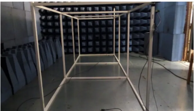
3.3. The Modular Structure
The modular structure consists of one-meter-long plastic pallets. They can be connected together to have a platform (see Figure 4) with notch tokens.
We made all the measurements with this platform by placing the two nodes of the Kit on a height of one meter and with a distance of 3 meters one from the other.
4. Operation of the Measuring System
We first note the function of the PDoA node DWM1002 which acts here as a slave. It also performs a TWR ranging with the DWM1003. And thanks to its two receivers DW1000, it calculates the range and the DPoA of the received sig-nals.
4.1. Implementing of the Communication between the Two Nodes
Note At start-up, the Mona Lisa listens to the Blink message of the tag and when it receives this message Blink, it responds to the tag with a message Ranging Config. This configuration message includes in particular the address of the
Figure 4. Modular structure.
PDoA node and the time parameters for the ranging phase. Thus, allowing the tag to execute a ranging with the Mona Lisa. At the reception of the Ranging Config message, the tag goes into ranging mode by periodically performing ranging exchanges with the Mona Lisa (Figure 5).
4.2. Starting the Ranging between the Nodes
As noted above, the Mona Lisa (node DWM1002) has two antennas and two DW1000 integrated circuits (one for each antenna).
The ranging always starts with the sending by the tag of a message that we will call here message 1, while the node DWM1002 is listening with only one active DW1000. When it receives the message message 1, it responds with a Response
message and the tag terminates the ranging exchange by sending a Final mes-sage. The Mona Lisa activates its two integrated circuits DW1000 to receive the final message (Figure 6).
On receipt of this last message, the Mona Lisa calculates the phase difference of Arrival (PDoA) between the arrival times at each antenna.
With the PDoA Kit you can collect several information including the PDoA, the X, Y coordinates of the tag and the distance between the two nodes. For the purposes of our study project, we have integrated a data recovery program into the system. It allowed us to collect and save on a CSV file the PDoA provided by the Kit but also the angle of rotation given by the stepper motor.
5. Presentation and Analysis of the Measurements Taken
We performed a series of measurements in two different environments. First in an anechoic chamber and then in a laboratory room and always in the same ar-chitecture (see Figure 7) and material operating conditions. These conditions include:
the pilotage of the Mona Lisa by the stepper motor presented above: To simulate the variation of arrival angle of the signals, we placed the receiving node (the Mona Lisa) on a stepper motor to rotate it from 0˚ to 180˚.
the addition of a first program to pilot the stepper motor with a step of 11.25 degrees, it also calculates and collect the angle of rotation after each step.
Figure 5. Establishing communication between the tag and the Mona Lisa.
Figure 6. Starting the ranging.
the addition of a second program to collect and save on a CSV file the value of the DPoA and the angle given by the stepper motor
The two nodes are put on the modular structures presented above
5.1. Measures
The measurements are made in an ideal environment (anechoic chamber) Fig-ure 8 and in a disturbed environment (a laboratory room) Figure 9. In these measurements, there are 600 values on each movement of the Mona Lisa with a
Figure 7. Architecture of the measuring system.
Figure 8. Measurement in the anechoic chamber.
Figure 9. Measurement in a room of the laboratory (Blagnac).
real rotation angle of 11.25˚ per displacement, so 17 taken (from −67.5˚ to 67.5˚). A repetition of the measurements shows an almost perfect reproducibility of the results obtained. However, as we will see in Table 1 and Table 2, meas-urements above −70 and 70 degrees give very high errors. This is also an indica-tion close to the one given by the manufacturer (best performance between -80 and 80 degrees). That is why in the analysis and the representation that we will proceed onto, we will limit ourselves into the interval −67.5˚ to 67.5˚.
Table 1. Summary of errors in the anechoic chamber.
Real angle (˚) Average error (˚) Maximum error (˚) Minimum error (˚)
−90 −26.76 −20.88 −32.36 −78.75 −18.11 −12.71 −23.93 −67.5 −12.68 −8.09 −16.35 −56.25 −9.01 −4.08 −13.13 −45 −5.77 −1.44 −9.88 −33.75 −3.33 0.97 −8.93 −22.5 −2.71 0.86 −7.61 −11.25 −2.85 1.58 −6.89 0 −1.34 2.01 −6.04 11.25 −0.89 3.52 −4.34 22.5 −0.50 5.52 −4.16 33.75 0.22 5.22 −4.22 45 0.99 5.77 −3.19 56.25 1.97 8.06 −2.56 67.5 −0.03 8.09 −8.08 78.75 51.84 167.13 −9.63 90 160.33 169.12 151.92
Table 2. Summary of errors in the lab room.
Real angle (˚) average error (˚) maximum error (˚) minimum error (˚)
−90 −29.37 −22.47 −35.17 −78.75 −17.01 −11.97 −21.69 −67.5 −8.69 −4.26 −13.22 −56.25 −1.97 2.56 −6.11 −45 1.77 6.15 −3.20 −33.75 4.23 8.05 0.18 −22.5 6.03 9.47 1.95 −11.25 5.38 9.96 1.58 0 5.70 10.44 2.01 11.25 4.87 9.24 0.13 22.5 4.82 9.67 0.22 33.75 5.22 10.39 −0.18 45 6.19 11.47 0.54 56.25 7.09 12.24 1.97 67.5 7.48 15.84 1.46 78.75 7.72 16.83 −1.74 90 53.74 178.38 1.62
5.2. Presentation of Measures
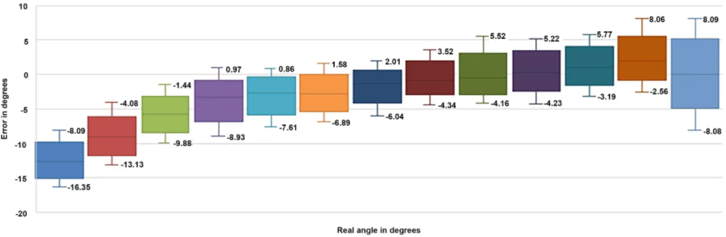
5.2.1. Measurements in the Anechoic Chamber
Measurements taken in the anechoic chamber are recorded in Table 1, and shown in Figure 10. As it seems, the absolute maximum error is 16.35 degrees. This error decreases very quickly if we approach the real zero-degree angle; that is to say when the two nodes are in line of sight (LOS). This configuration in LOS gives the best performance of the measurement kit. Besides the absolute maximum errors of 16.35 and 13.13 degrees respectively obtained with the real angles of −67.5 degrees and −56.25 degrees, the absolute maximum error is be-low 10 degrees. With a symmetrical distribution of measurements, this symmet-rical distribution of the measurements is materialized by the equality of the av-erage values and medians of the boxplots representing these measurements. The size of the boxes reflects the difference between the different measurements taken for the same real angle. This gap becomes larger if one moves away from the zero-degree angle and as a result the boxes become larger.
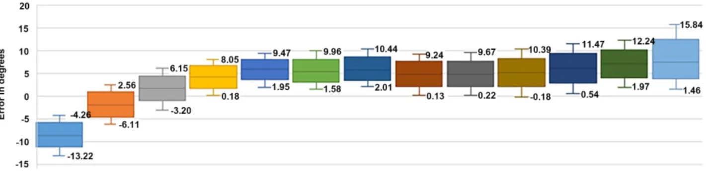
5.2.2. Measurements in the Laboratory Room
The data obtained by measurements in the lab room are recorded in Table 2 and shown in Figure 11. They show that the absolute maximum error is 15.84 de-grees for an actual angle of 67.5 dede-grees (an overestimate of the true value). After this maximum and that of 12.24 degrees obtained by measuring the actual angle 56.25 degrees, other errors remain below 12 degrees. With the observation that the error reduction is no longer exclusively related to antenna position (close to the actual angle zero degree or not) as was the case in the anechoic chamber.
5.2.3. Discussion
The majority of the absolute maximum errors noted in the anechoic chamber as well as those noted in the lab room are around 10 degrees. Moreover, except for the errors obtained with the real angles of −67.5 and −56.25 degrees, all the other errors obtained in the lab room give an overestimation of the real value, unlike those obtained in the anechoic chamber. With rather small differences between
Figure 11. Representation of angular errors according to the actual angles in the lab room.
Figure 12. Representation of mean angle of arrival measurement errors in both cases.
the measurement errors obtained in the anechoic chamber and those obtained in the laboratory room. These average differences are mostly below 5 degrees as shown in Figure 12 which represents the mean values of the two types of meas-ures.
6. Conclusion and Perspectives
In this article, we have studied the performance of the PDoA Kit. This study first shows us the limits of the Kit with angles at most −70 to 70 degrees. It also shows overall absolute maximum errors in an ideal environment around 10 degrees, and fairly small and stable differences between measurements in an ideal and real environment around 5˚ on average.
Given these results of analysis, it would be interesting to see on the one hand the real impact of these errors on the actual location of the nodes in coupling the value of the AoA, the distance obtained by TWR ranging and a location algo-rithm, for integration of this arrival angle measurement system into our mobile target localization project.
Given the limits of Mona Lisa (from −70˚ to 70˚), it would be interesting to propose in our upcoming studies a triangular localization system composed of three Mona Lisa for a 2D localization, or even a tetrahedral pyramid location system composed of 4 Mona Lisa for a 3D location. This system will use the pa-rameter AoA and the distance obtained by ranging TWR for an outdoor location or an improved TWR ranging for an indoor location.
Also, we did this study with only two nodes (a Mona Lisa and a tag). It would be interesting to extend the network and thus have several mobile tags and sev-eral Mona Lisa and therefore, propose a topology and a location protocol adapted.
Acknowledgements
The authors would like to thank CEA-MITIC of the UFR SAT at the University Gaston Berger of Saint-Louis/Senegal for his financial support for the travel to Toulouse (France) and the publication of this work.
Conflicts of Interest
The authors declare no conflicts of interest regarding the publication of this pa-per.
References
[1] Fofana, N.I., Van den Bossche, A., Dalce, R. and Val, T. (2016) Proto-typage et analyse de performances d’un système de ranging pour une localisation par UWB. In: 16 éme Colloque Francophone sur l’Ingénierie des Protocoles (CFIP 2015), Par-is, 22 July 2015-24 July 2015.
[2] Diagne, S., Val, T., Farota, A.K. and Diop, B. (2018) Comparative Analysis of Ranging Protocols for Localization by UWB in Outdoor. Wireless Sensor Network, 10, 103-117. https://doi.org/10.4236/wsn.2018.105006
[3] Hou, Y., Yang, X. and Abbasi, Q.H. (2018) Efficient AoA-Based Wireless Indoor Localization for Hospital Outpatients Using Mobile Devices. Sensors, 18, 3698.
https://doi.org/10.3390/s18113698
[4] Schüssel, M. (2016) Angle of Arrival Estimation Using WiFi and Smartphones. 2016
International Conference on Indoor Positioning and Indoor Navigation (IPIN), 4-7 October, Alcalá de Henares, Spain.
[5] http://www.bluetooth.com/
[6] Dotlic, I., Connel, A., Ma, H., Clancy, J. and McLaughlin, M. (2017) Angle of Arriv-al Estimation Using Decawave DW1000 Integrated Circuits. 2017 14th Workshop on Positionning Navigation and Communications (WPNC), Bremen, 25-26 Octo-ber 2017, 1-6. https://doi.org/10.1109/WPNC.2017.8250079
[7] Zhang, Y.W., Brown, A.K., Malik, W.Q. and Edwards, D.J. (2008) High Resolution 3-D Angle of Arrival Determination for Indoor UWB Multipath Propagation. IEEE Transactions on Wireless Communications, 7, 3047-3055.
https://doi.org/10.1109/TWC.2008.060979
[8] Xu, J., Ma, M. and Law, C.L. (2008) AOA Cooperative Position Localization. 2008
IEEE Global Telecommunications Conference, New Orleans, LO, 30 November-4 December 2008. https://doi.org/10.1109/GLOCOM.2008.ECP.720
[9] Jiang, J.-R., Lin, C.-M., Lin, F.-Y. and Huang, S.-T. (2012) Alrd: Aoa Localization with Rssi Differences of Directional Antennas for Wireless Sensor Networks. Inter-national Conference onInformation Society (i-Society), June 2012, 304-309. [10] Wang, J., Vasisht, D. and Katabi, D. (2014) RF-IDraw: Virtual Touch Screen in the
Air Using RF Signals. Proceedings of the 2014 ACM Conference on SIGCOMM, Chicago, Illinois, 17-22 August 2014, 235-246.
https://doi.org/10.1145/2619239.2626330
[11] Krishnaveni, V., Kesavamurthy, T. and Aparna, B. (2013) Article: Beamforming for Direction-of-Arrival (DOA) Estimation-A Survey. International Journal of Com-puter Applications, 61, 4-11. https://doi.org/10.5120/9970-4758
[12] http://www.decawave.com/


![Risiko- & [und] Schutzfaktoren der psychischen Gesundheit humanitärer Einsatzhelfer : eine systematische Literaturübersicht](data:image/gif;base64,R0lGODlhAQABAIAAAP///wAAACH5BAEAAAAALAAAAAABAAEAAAICRAEAOw==)