HAL Id: hal-01416367
https://hal.inria.fr/hal-01416367
Submitted on 21 Sep 2018
HAL is a multi-disciplinary open access
archive for the deposit and dissemination of
sci-entific research documents, whether they are
pub-lished or not. The documents may come from
teaching and research institutions in France or
abroad, or from public or private research centers.
L’archive ouverte pluridisciplinaire HAL, est
destinée au dépôt et à la diffusion de documents
scientifiques de niveau recherche, publiés ou non,
émanant des établissements d’enseignement et de
recherche français ou étrangers, des laboratoires
publics ou privés.
Multichannel Wireless Sensor Networks for Structural
Health Monitoring of Aircraft and Launchers
Pascale Minet, Gerard Chalhoub, Erwan Livolant, Michel Misson, Ridha
Soua, Rana Diab, Badr Rmili, Jean-Francois Perelgritz
To cite this version:
Pascale Minet, Gerard Chalhoub, Erwan Livolant, Michel Misson, Ridha Soua, et al..
Multichan-nel Wireless Sensor Networks for Structural Health Monitoring of Aircraft and Launchers. Habib
Rashvand and Ali Abedi. Wireless sensor systems for extreme environments: space, underwater,
underground and industrial, John Wiley, 2017. �hal-01416367�
Multichannel Wireless Sensor Networks for
Structural Health Monitoring of Aircraft and
Launchers
Pascale Minet
∗, Gerard Chalhoub
†, Erwan Livolant
∗, Michel Misson
†, Ridha Soua
∗, Rana Diab
†,
Badr Rmili
‡and Jean-Francois Perelgritz
§∗ Inria Paris, 2 rue Simone Iff, CS 42112, 75589 Paris Cedex 12, France † Clermont University, 5 avenue Blaise Pascal, 63178 Aubiere, France ‡ CNES Launcher Directorate, 52 rue Jacques Hillairet, 75012 Paris, France
§Airbus Group Innovations, 12 rue Pasteur, 92150 Suresnes, France
Structural health monitoring has recently been applied to Aircraft and Launchers, in which the number of interconnected devices is constantly increasing. Up to now, wired networks have been used, but their high mass leads to increased fuel con-sumption and high carbon emissions. Wireless sensor networks would certainly reduce the mass and complexity of wiring, yet the essential question is: are they able to meet the require-ments of non-critical and health monitoring applications in the specific environment of Aircraft and Launchers? First, we unify the requirements of non-critical and health monitoring applications in Aircraft and Launchers, and we show that such requirements impose the choice of multichannel mesh wireless networks. Multichannel networks bring many advantages in terms of latency, throughput and robustness. However, they do raise a number of challenges, some of which are general, while others are specific to supporting data gathering applications. Different solutions from the state-of-the art are given. These solutions, whether designed to take into account the specifici-ties of data gathering or not, range from medium access control to multihop routing. The best performances are obtained when both problems are tackled together. We establish bounds on the minimum number of time slots needed by a raw data convergecast, taking into account the number of available channels, the number of children of the sink in the routing tree, as well as the number of radio interfaces in the sink. We propose SAHARA, a solution that provides an adaptive multichannel collision-free protocol for data gathering and we present many performance results obtained by simulation.
I. CONTEXT
Structural health monitoring is an emerging technology where structures are monitored and inspected for their capacity to serve their intended purpose. Damage and malfunctioning are detected and analyzed. Structural health monitoring has re-cently been applied to aircraft. However, the physical systems used in aircraft are becoming more and more complex due to the growing number of interconnected components and the increasing volume of data exchanged. Automated prognostic and health monitoring systems have been proposed to address
this issue. Basically, these systems require sensor networks where different types of sensors are integrated in the aircraft to sense several parameters such as temperature, vibration and pressure. Each sensor performs a measurement point and then transmits its data to a central entity using wires. The central entity gathers all the data transmitted in the network for further analysis. Nevertheless, some intrinsic characteristics of wires, such as overall weight, cost and proneness to breaks and degradation, are hampering the use of wires and the integration of sensors in aircraft. Consequently, there is an urgent need for wireless health monitoring systems that mitigate the above-mentioned limitations.
Today, Wireless Sensor Networks (WSNs) are revolution-izing not only home and factory monitoring, but also the aerospace industry. It is argued that transitioning from wired sensor networks to WSNs will radically reduce the amount of wiring [1]. Are WSNs able to meet the requirements for Aircrafts and Launchers?
For the sake of readability, this paper uses the term ”Air-craft” to cover both Aircraft and Launchers.
A. Expected benefits of WSNs in aircraft
Generally speaking, the benefits of WSNs in Aircraft would be a reduction in the complexity and mass of wiring. For instance, cables account for 70% of the 1.5 tons of Ariane 5 avionics mass [2]. The wiring length of a Boeing 747-400 is about 270 km and the most recent and most complex Airbus A380 has over 530 km of cable [3]. Moreover, cable routing is challenging in this harsh environment where electrical signal cable must be physically separated to avoid electrical interference. The Developmental Flight Instrumentation (DFI) for Orion Exploration Flight Test 1 (EFT-1) weighs 544 kg for 1200 channels and wires represent 57% of the total weight of the Developmental Flight Instrumentation data system .
A NASA study [4] has shown a significant potential mass improvement for the Developmental Flight Instrumentation (DFI) for future Orion missions:
• Miniaturization, optimized architecture and equipment
distribution lead to “54 kg total DFI system mass (100% wired)” for 400 channels.
• Whereas wireless leads to “38 kg total DFI system mass (100% wireless)” for 400 channels.
An easy computation in [4] shows that the mass per channel for a wiring approach is 0.45 kg. This mass can be reduced to 0.19 kg using a miniaturized and optimized wired approach, whereas a fully wireless approach has a mass of 0.09 kg per channel. Similar studies conducted on the Ariane launcher have also shown large mass improvements in instrumentation and telemetry subsystems.
Subsequently, fuel efficiency is improved and carbon emis-sions are reduced. In addition, replacing wires by wireless connections facilitates the addition or removal of sensors, and introduces the possibility of installing sensors in locations previuosly inaccessible due to wiring constraints. Thus, more sensors can be deployed to ensure system redundancy. B. WSN requirements for aircraft
To cope with Aircraft constraints and specific environments, unified WSN requirements have been defined by Aircraft man-ufacturers and End-Users in the SAHARA project, supported by the French Aerospace cluster ASTech. This project, led by Airbus Group Innovations, started at the end of 2011 and comprises academics (CNES, ECE, EPMI, Inria, LIMOS), aircraft manufacturers acting as end users (Airbus Group Innovations, Airbus Defence and Space, Airbus Helicopters, Safran-ES), as well as small and medium-size businesses (BeanAir, GLOBALSYS, OKTAL-SE, ReFLEX-CES).
In order to shorten development time and to ease the technology adoption in aircraft, SAHARA is focused only on non-critical sensors and Health Monitoring Sytems (HMS) and is based only on available and mature Commercial Off-The-Shelf (COTS) technologies. The goal of this project is to develop existing wireless technologies and COTS and adapt them into a generic and adaptive WSN dedicated to Aircraft. The scope of the project covers the definition of unified WSN requirements, the development of WSN technologies and protocols, the development of WSN demonstrators, tests in representative Aircraft environments and the development of on-board radio frequency propagation models.
The unified requirements cover different types of Aircraft and Launchers. This chapter focuses only on non-critical and Health Monitoring System (HMS) measurements. These requirements can be summarized as follows:
• Static sensors such as temperature, pressure, etc.;
• Dynamic sensors such as vibration, shock, strain gauges, etc.;
• Sampling rate: from a few samples per hour to 10 ksps;
• Sensor network with various sampling rates;
• Sensor nodes per network: 1 to 50;
• Expected battery capacity for a sensor node: from 40 minutes to 14 hours in active mode and 24 months in sleep mode;
• Sensor nodes integrated in a confined environment
lead-ing to propagation issues;
• Sensor nodes integrated in aircraft fuselage, empennage, wings, engine, landing gear; launcher stage, fuel tank, payload fairing are at a distance from the closest sink that is greater than the communication range of the nodes, leading to multihop communication;
• Latency from a sensor node to the closest sink ranges from 100 to 500 ms;
• Measurement dating accuracy from 1 to 100 µs, etc. Therefore, to meet these strong requirements in terms of latency, energy efficiency and reliability, low power wireless mesh networks have been introduced. In addition, to meet determinism and latency constraints, a time slotted and mul-tichannel medium access control is required.
C. Previous related work
There have been many projects dealing with the integration of wireless technologies in aircraft systems. We list several below and present their objectives.
The Integrated WIreless SEnsing (WISE) European project [5] aimed at:
• enhancing the aircraft monitoring system by
deploy-ing new wireless technologies involvdeploy-ing low power au-tonomous sensors;
• allowing the monitoring of new parameters which did not emerge in the monitoring of physical links;
• continuing the monitoring or improving redundancy when the physical link would be impaired;
• improving information segregation.
The final goal was to reduce the aircraft operating and installation costs, improve the availability and dispatch rate through a simplification in the maintenance system, reduce the cost of ground and flight test installation due to wire removal, improve the man-machine interface as well as reduce the accident rate.
The @MOST SWAN project [6] embraced all engineering issues related to a new aeronautical system, from defining applications and capturing requirements to developing a prototype, and including investigations on aircraft regulation and certification as well as security, safety and reliability issues required to design an aircraft systems architecture integrating Wireless Sensor Networks (WSN). The main objectives of SWAN were to provide solutions relying on WSN technology for maintenance operations with increased efficiency compared to current approaches and to identify potential improvements in different aircraft domains (e.g. aerodynamics, engine, cabin, systems and structure) where the overall aircraft maintenance could benefit.
The AUTOnomous SENSing microsystem, (AUTOSENS) project [7] focused on energy harvesting for autonomous wireless sensors embedded in aircraft. The architecture
proposed takes into account the specificity of the targeted environment. One module manages energy for sensing and processing whereas another module manages energy for communication.
The System for Mobile Maintenance Accessible in Real Time, (SMMART) European project [8] investigated a new integrated concept to answer the maintenance challenges of the transport industry (i.e. aeronautics, road transport, marine transport):
• to reduce the time and cost for scheduled and unscheduled maintenance inspections of increasingly sophisticated and complex products;
• to remotely provide the adequate up-to-date information to assist the mobile workers in all their tasks wherever they operate;
• to minimize the cost penalties of unscheduled downtime
on large transport fleets. The technology used was based on Radio Frequency IDentification (RFID).
Although these projects have ended, their results have not been made public. It is nonetheless worth noting that all these projects considered wireless technologies to be very promising for preventive maintenance and structural health monitoring in aircraft. However, the autonomy of wireless sensors remains a challenging issue.
D. Paper organization
This paper is organized as follows. Section II describes the challenges resulting from multichannel use and presents different solutions from the state-of-the art to address them. Section III focuses more particularly on challenges raised by data gathering applications and gives examples of solutions. Section IV presents SAHARA, a solution designed to be compliant with the unified WSN requirements for Aircraft and the IEEE 802.15.4 COTS . Finally, in Section V, issues are discussed and perspectives are given. This chapter is an extended version of the paper [9] published at the IEEE WISEE 2015 conference.
II. GENERAL MULTICHANNEL CHALLENGES
In a multichannel network, several channels are used si-multaneously by nodes to communicate. Additional challenges arise for communication protocols in multichannel networks. In this section, we will discuss these challenges and present solutions from the state-of-the art.
A. Signal propagation in an aircraft cabin or inside a launcher The analysis and behavior prediction of 2.4 GHz signal in an enclosed area is subject to the physical conditions in which these signals will propagate. At this relatively short wavelength (12.5 cm), reflection from lateral walls, ceiling surfaces, diffraction on seats, headrests as well as people, refraction by metallic or hard surfaces are important. These various parameters render the signal analysis task fairly complex. The important parameters for an adequate signal characterization,
such as propagation path loss, delay spread and coherence bandwidth must be validated using both simulation results and experimental results.
Also, since the cabin in itself is normally made up of hard surfaces, the possibilities of multipath propagation due to high energy successive reflections on the walls and ceiling must be characterized in order to select a proper signal modulation and symbols speed to avoid excessive Inter-Symbol-Interference. The noise level, due to other transmitting devices onboard (such as on-board WiFi or on-board BlueTooth) as well as possible interference of the proposed system must be fully understood prior to final system design. All these considera-tions lead us to consider a multihop and multichannel adaptive solution. There have been publicly available measurements and contributions dealing with signal propagation in the 2.4 GHz ISM frequency band in enclosed areas such as trains. In [10] and [11], rigorous studies to acquire a working knowledge of these parameters have been done. Results show that due to the many reflections from metallic or hard surfaces, the path loss exponent was found to be smaller than the one used to characterize signal propagation in free space. The positioning of the transmitting/receiving antennas has also been found to be, in many cases, critical for adequate transmission at all times. Hence, simulation models have to be properly modified to correctly predict either the coherence bandwidth or the delay spread. The time-variability of the radio link parameters is probably much more important for an aircraft cabin than for a particular level of a launcher. Experimental investigations are absolutely necessary for such confined and obstructed areas. B. Mesh multichannel wireless networks
Even though the size of an airplane or of a launcher is not that large (less than 80m x 80m for an airplane) compared to an average communication range in the 2.4 GHz frequency band, the complexity and the time-varying behavior of the wireless medium led us to consider a multihop topology allowing multipath for data, thanks to the natural redundancy of such topologies. Also, for reliability reasons, a single point of failure should be avoided. As a consequence, star topologies are not suitable. Mesh topologies are preferred because if link or node failure occurs, another route to the destination can be found.
C. Network build-up
During the network build-up phase, nodes try to be part of the network in order to be able to exchange and relay data packets. When a node is activated, it usually starts with a network discovery phase during which it scans for existing networks. The scanning procedure in a multichannel network is not trivial. A new node should be able to detect an activity on a certain channel and try to communicate with this network in order to gain access and be part of it. Special advertisement frames, usually named beacons, are used for signaling the presence of the network. This is the case in WiFi [12] and ZigBee [13], for example.
The challenge lies in making sure that the new node is able to find the network. In other words, the node should be able to be on the same channel at the same time as its neighboring nodes that have already joined the network. Without a fixed and known control channel, this procedure can last a considerable time and, in some cases, drain a lot of the node energy resources.
One solution to make this phase less time and energy consuming would be to exchange control traffic on a fixed and known channel. This would allow new nodes to scan only one channel. On the other hand, nodes should periodically switch to this control channel and send beaconing frames in order to be detected by new nodes.
D. Node synchronization
When guaranteeing access to the medium and a maximum end-to-end delay in a multi-hop network, node synchronization becomes a must. The fact that nodes are working on different channels makes it even more important to have network scale synchronization in order to manage network discovery and neighborhood updates. Protocols such as TSCH of the IEEE 802.15.4e are based on one-hop synchronization in order to allocate timeslots on multiple channels.
Extending this synchronization in order to reach nodes that are multiple hops away is a challenge. It could be achieved using an external synchronization device, but the difficult part would be to make sure that this device can be reached by all the nodes of the network. For example, synchronizing nodes using a Global Positioning System (GPS) is only possible when all the nodes are able to communicate with satellites. In addition, this has consequences on the weight and energy consumption of nodes.
Another approach would consist in achieving relative syn-chronization based on an internal reference that is part of the network. For instance, a designated node in the network could broadcast a synchronization beacon that is propagated by other nodes in order to reach all the nodes of the network. Similar approaches have been studied in [14] and [15].
E. Selection of channels
Wireless standards based on IEEE 802.15.4 have 16 avail-able channels in the 2.4 GHz frequency band. Other wireless standards such as Wi-Fi and Bluetooth also use the 2.4 GHz band. This makes IEEE 802.15.4 networks vulnerable to inter-ference coming from other nearby networks, including other IEEE 802.15.4 networks. We call this external interference. External interference happens when nodes of the network re-ceive perturbations coming from sources that are not part of the network. Furthermore, internal interference is caused by nodes that are part of the network. Depending on the modulation and the frequencies used in the physical layer, nodes using the same channel are prone to generate interference. In order to avoid interference, orthogonal channels should be used.
Internal interferences can be avoided using channel assign-ment techniques, discussed in the following section (Section II-F). In order to avoid external interferences, a scan is usually
carried out to identify the energy level that is detected on each channel. The scan procedure should result in what is called a channel blacklist, which is a list of channels that should not be used in the network.
This blacklisting technique can be done in a distributed manner. Every node in the network scans its own environment and builds its own blacklist. This local blacklist is then used locally to choose a convenient channel, or is sent to a controller node that is in charge of distributing channels to all the nodes of the network. This of course generates a significant delay before being able to choose a channel. In addition, if interference is not stable (which is most usually the case), the channel blacklist should be updated frequently. Blacklisting channels can also be achieved for the whole network. This allows the frequency band to be segmented over different networks in order to enhance performance while avoiding external interferences. This can be achieved if nearby networks are manageable, but this is often not the case.
F. Channel assignment
Channel assignment represents one of the main challenges of multichannel MAC protocols. Constrained by the cost and the size, most of the nodes are equipped with one radio transceiver. Thus most of the protocols propose solutions to allow nodes either to send or to receive at a time, using only one radio transceiver. Some assignment schemes allocate channels for the receivers, whereas others for the transmitters. Some protocols also combine channel allocation with time slots allocation.
Some protocols such as [16] propose a static channel assign-ment where nodes keep using the same channel until neighbor-hood or interference conditions change and force them to seek a more suitable channel. This approach is often lightweight and does not waste energy due to frequent channel switchings. Other protocols such as [17], [18], [19], use a semi-dynamic channel assignment where nodes switch channels according to the destination. This approach is adaptive and allows more flexibility in choosing suitable channels. A more dynamic channel assignment method consists in changing channels at each transmission such as [20], [21]. This approach is more robust because it avoids bad channels and enables nodes to use all available channels, but at the cost of energy and time wasting due to frequent channel switchings.
Protocols such as [22] and [23] propose a multi-interface sink in order to enhance the reception throughput of this particular node. Indeed, assigning different channels to the sink transceivers allows simultaneous receptions.
G. Network connectivity
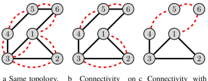
Multichannel assignment solutions may differ in the as-sumptions made regarding network connectivity, as illustrated in Figure 1, where channel ch1 is represented by a solid black line whereas channel ch2 is depicted in dashed red line: a) The same topology exists on all channels and connectivity
b) The topology may differ from one channel to another but connectivity is assumed at least on one channel, usually the channel used for control messages; this assumption is frequently made. For instance, in Figure 1, there are two disconnected parts on channel ch2.
c) Several channels are needed to ensure network connectiv-ity. This is the most permissive assumption.
1 2 3 4 5 6 a Same topology. 1 2 3 4 5 6 b Connectivity on one channel. 1 2 3 4 5 6 c Connectivity with two channels.
Fig. 1: Different cases of connectivity.
H. Neigborhood discovery
For any node u, a node v is said to be a one-hop neighbor of u on channel c if and only if u is able to receive messages from v on channel c and v is able to receive messages from u on channel c: a symmetric link exists between them on channel c. Some solutions do not check the symmetry of a link before using it. This will cause useless retransmissions when an acknowledgment is required and the link is not symmetric [24]. Notice that in a real multichannel environment, a node may be a one-hop neighbor on one channel and not on another one [25]. There are different types of solutions according to the assumptions made, assumptions similar to those on network connectivity. The simplest ones perform neighborhood discov-ery on only one channel, usually the control channel, whereas the most sophisticated ones perform as many neighborhood discoveries as channels used. Some solutions take advantage of large similarities of links between channels to store this knowledge efficiently.
I. Medium access control
Multichannel Medium Access Control (MAC) protocols that have been proposed in the literature use either Time Division Multiple Access (TDMA), or Carrier Sense Multiple Access with Collision Avoidance (CSMA/CA), or a combination of both techniques. In what follows we briefly describe the best-known multichannel protocols.
1) Contention based protocols: In [17] the authors pro-posed Multichannel Access for Sensor Networks, (MASN), a multichannel protocol for hierarchical ZigBee networks with many-to-one transmissions. Assignment of the different channels is centralized by a coordinator and based on the hierarchical address assignment process used in ZigBee. The main advantage of this solution is its simplicity of integration in IEEE 802.15.4 devices with slight modifications in the MAC layer. However, the authors used a single topology for the
simulations which might be the most convenient topology for MASN.
In [19], the authors proposed Multi-frequency Media access control for wireless Sensor Networks, (MMSN), which uses a semi-dynamic channel assignment approach for channel allo-cation based on different strategies. Strategies differ according to the level of overhead and the effectiveness of the channel allocation. At the beginning of each time slot, nodes contend for the medium to broadcast control traffic on a common broadcast channel. When a node transmits a packet, it switches between its own channel and the destination channel during the preamble sending time, which results in increasing the protocol overhead and the number of repetitions due to frequent channel switchings.
2) Contention-free based protocols: In [21], the authors proposed the Multi-Channel Lightweight MAC protocol, (MC-LMAC), which guarantees that the same slot/channel pair is not simultaneously used in the neighborhood up to two hops. MC-LMAC suffers from the overhead of the control messages that are exchanged in order to discover the channels used in the neighborhood up to two hops. The problem increases with network density.
In [26], the authors proposed Time Synchronized Mesh Protocol, (TSMP) on which industrial standards such as WirelessHART and ISA100.11a are based, as well as IEEE 802.15.4e. It uses a channel-hopping technique to enable nodes to switch channels at each transmission. However, one drawback is its inability to support changes in topology.
3) Hybrid protocols : An Energy-Efficient Multi-channel MAC Protocol for Dense Wireless Sensor Networks, called Y-MAC, [27] is based on algorithms proposed in LMAC and MMSN. Time slots are assigned to the receivers. It allows new nodes to join the network and assigns time slots in a dynamic way. At the beginning of each time slot, potential senders to the same receiver compete in order to access the medium using a CSMA/CA algorithm. Multiple packets are sent successively on different channels, the receiver and the sender hop to a new channel according to a predetermined sequence. Y-MAC reduces latency by offering the possibility for nodes that were not able to send their traffic to compete in a consecutive slot. However, the channel allocation method is not detailed in the paper: the authors only insist on not using the same channel in one-hop neighborhood which leads to high interference caused by simultaneous transmissions received from nodes that are two hops away.
In [18] the authors proposed an Energy Efficient hybrid MAC for WSN, (EE-MAC). It is a centralized protocol that uses a semi-dynamic channel assignment approach for channel allocation. EE-MAC operates in two phases, a setup phase and a transmission phase. During the first phase, neighbor discovery, slot assignment, and global synchronization are achieved. These operations run only during the set-up phase and every time a change in the topology occurs. During the transmission phase, time is divided into time slots. Each slot is divided into schedule subslots and contention subslots. Each cycle starts with scheduled slots followed by contention
slots. Nodes use Low Power Listening,(LPL) [28] during contention slots and send Hello messages to the base station. EE-MAC suffers from the overhead of Hello messages that are exchanged and sent to the base station.
In [20], the authors proposed the Multi-Channel MAC protocol, (MuChMAC). It uses a dynamic channel assignment approach. Time is divided into slots. Each node is able to independently choose its receiving channel switching sequence based on its identifier and the current slot number using a pseudo-random generator. A broadcast slot is inserted every n slots. These common broadcast slots also follow a pseudo-random channel hopping sequence. A sender is thus able to calculate the channel of the receiver. The main drawback of MuChMAC is that channel allocation is based on a random mechanism that does not take into consideration the channel usage in the neighborhood.
In [22], the authors proposed the Hybrid Multi-Channel MAC protocol (HMC-MAC) that is based on TDMA for signalling traffic and CSMA/CA combined with FDMA for data exchange. Time is divided into intervals. A TDMA interval is dedicated for neighbor discovery and the channel allocation process. HMC-MAC aims at reducing the control traffic overhead. It allows nodes to share slots on the same channel in order to send data to the same destination. Results in [29] show that it enhances network performance in terms of the number of collisions and also packet delivery rate. However, it suffers from high end-to-end delays due to packet accumulation in nodes close to the sink.
J. Dynamic multihop routing
The energy constraints of sensor nodes raise challenging issues in the design of routing protocols for WSNs. Proposed protocols aim at load balancing, minimizing the energy con-sumed by the end-to-end transmission of a packet and avoiding nodes with a low residual energy. Initially designed for a single-channel network, they can also be used for multichannel networks. Different families of multihop routing protocols can be distinguished:
• Data centric protocolssend data only to interested nodes in order to avoid useless transmissions. Such protocols make the assumptions that data delivery is described by a query driven model. Mainly, two approaches are proposed for interest dissemination. The first is Sensor Protocols for Information via Negotiation (SPIN) [30] where any node advertises the availability of data and waits for requests from interested nodes. The second is Directed Diffusion (DD) [31] in which the sink broadcasts an interest message to sensors, and only interested nodes reply with a gradient message. Hence, both interest and gradient messages establish paths between the sink and interested sensors. Many other proposals have been made, such as rumor routing, gradient-based routing, etc.
• Hierarchical routing determines a hierarchy of nodes to simplify routing and reduce its overhead. The most fa-mous hierarchical routing protocol is Low-Energy Adap-tive Clustering Hierarchy (LEACH) [31]. LEACH
orga-nizes sensor nodes into clusters with one node acting as a cluster head. To balance energy consumption, a random-ized rotation of the cluster head is used. Power-Efficient GAthering in Sensor Information Systems (PEGASIS) [31] enhances LEACH by organizing all the nodes into a chain where the head of the chain varies.
• Opportunistic routing takes advantage of the broadcast nature of wireless communications or node mobility. The first techniques maintain multiple forwarding candidates for any given node and select the forwarding candidate taking into account the transmission made. In [32], the authors highlight how these protocols achieve better energy efficiency. The second techniques merge routing and mobility to obtain smaller energy consumption when compared to classical techniques. They use mobile sinks [33], [34], mobile relays [35] or data mules [36], [37] when the connectivity of the network is not permanently ensured.
• Geographical routing uses the geographical coordinates of the nodes to build routes. In [31], the authors propose a Geographic and Energy Aware Routing (GEAR) pro-tocol, where any message is forwarded first to the target region, and second to the destination within the region. Geographic Adaptive Fidelity (GAF) [31] builds virtual grids based on location information of the nodes. In each cell, a single node is active and routes messages, all the other nodes are sleeping.
• Routing selecting routes based on energy criteria. Such
routing protocols [38] should avoid nodes with a low residual energy to maximize the network lifetime. They should also save the energy of nodes by selecting routes that minimize the energy consumed by the end-to-end transmission of packets on the routes selected.
K. Energy efficiency
The most challenging concern in WSN design is how to save node energy while maintaining the desirable network behavior. Any WSN can only fulfill its mission as long as it is considered alive, but not after that. As a consequence, the goal of any energy efficient technique is to maximize network lifetime. This depends drastically on the lifetime of any single node.
To fulfill the mission required by the application, sensor nodes consume energy in sensing, processing, transmitting and receiving data. Hence, minimizing the data processed will save the energy of very constrained sensors. In addition, redundancy inherent to WSNs will produce many similar reports that are routed in the WSN. Communication is a greedy consumer of energy, as confirmed by experimental results.
1) Reasons for energy waste: With regard to communica-tion, there is also a great amount of energy wasted in states that are useless from the application point of view, such as:
• Collision: when a node simultaneously receives more than one packet, these packets collide. All colliding packets are discarded. If the senders want their packets to be received by their destinations, they retransmit them.
• Overhearing: energy is wasted by nodes that are within
the transmission range of the sender but are not the intended destination.
• Control packet overhead: the number of control packets should be minimized to leave the bandwidth available for data transmissions.
• Idle listening: is one of the major sources of energy dissipation in MAC protocols. It happens each time a node is listening to an idle channel in order to receive possible traffic.
• Interference: when a node receives a packet but cannot decode it.
A wide range of techniques aimed at minimizing energy consumption and improving network lifetime, has been pro-posed.
2) Classification of energy efficient techniques: We can identify five main classes of energy efficient techniques, namely, data reduction, protocol overhead reduction, energy efficient routing, duty cycling and topology control.
1) Data reduction: reduces the amount of data produced, processed and transmitted. Data compression and data aggregation are examples of such techniques.
2) Protocol overhead reduction: increases protocol effi-ciency by reducing the overhead. Different techniques exist. Tuning the transmission period of control messages to the stability of the network is an example of such tech-niques. More generally, optimizations based on a cross-layering approach between the application, the network and the MAC layers are other examples.
3) Energy efficient routing: maximizes network lifetime by minimizing the energy consumed when a packet is trans-mitted from its source to its final destination. Opportunis-tic routing, hierarchical routing, data centric routing, ge-ographical routing and routing selecting routes according to energy criteria constitute the main examples of energy-efficient routing. Multipath routing protocols use multiple routes to achieve load balancing and robustness against route failures.
4) Duty cycling: duty cycling means the fraction of time nodes are active during their lifetime. Nodes sleep (re-spectively active) schedules should be coordinated to meet application requirements. These techniques can be further subdivided:
• High granularity techniques focus on selecting active
nodes among all the sensors deployed in the network.
• Low granularity techniques switch off the radio of
active nodes when no communication is required and switch on the radio when a communication involving this node may occur. They are highly related to the medium access protocol.
5) Topology control: reduces energy consumption by adjusting transmission power while maintaining network connectivity. A new reduced topology is created based on local information.
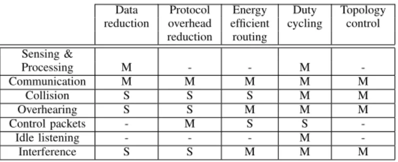
Table I shows the impact of each energy efficient technique on sources of energy waste. The ’M’ symbol denotes a main impact, and a ’S’ symbol a secondary impact.
TABLE I: Impact of energy efficient techniques on sources of energy waste.
Data Protocol Energy Duty Topology reduction overhead efficient cycling control
reduction routing Sensing & Processing M - - M -Communication M M M M M Collision S S S M M Overhearing S S M M M Control packets - M S S -Idle listening - - - M -Interference S S M M M
L. Robustness and adaptivity of WSNs
As discussed in Section II-B, signal propagation in confined areas such as airplanes and launchers is prone to link failures due to the complex nature of the surroundings. In order to ensure a robust protocol, nodes should be able to adapt to the changing link conditions on the MAC level and the routing level. In many real deployments, the WSN encounters dynamic changes. Hence, it is not sufficient to have a WSN operational. This WSN must also self-adapt to:
• Topology changes.This is usually provided by the routing protocol, that automatically selects a new route when the current one breaks.
• Traffic changes. An adaptive time slot and channel as-signment must take into account the traffic changes, in order to assign more slots to nodes that have a higher load.
• Environment perturbations. These perturbations can be due to an external source of perturbation such as a radar, or an internal one (e.g. interference within the WSN considered). The MAC and routing protocols used should be able to select the channels that are not subject to perturbations in order to improve the delivery rate and more generally the quality of service experienced by the users.
III. MULTICHANNEL CHALLENGES FOR DATA GATHERING SUPPORT
Data gathering applications represent the most typical ap-plications supported by WSNs in aircraft. Each node senses its environment and generates data that are transferred to the sink in charge of collecting and processing them. Each sensor node plays the role of data source and/or router node to deliver data messages to the sink, without aggregation by intermediate routers. This data collection is called raw data convergecast.
Two key issues for data convergecast concern: (1) mini-mized latencies and guaranteed packet delivery, and (2) energy saving. Minimized end-to-end delays ensure the freshness of collected data. In addition, guaranteed packet delivery leads to a more accurate monitoring. A limiting factor for a fast data
collection is interference. To mitigate this problem, researchers resort to multichannel communications. Indeed, multichannel communications are exploited to increase, on the one hand, network capacity with parallel transmissions and, on the other hand, robustness against internal or external perturbations. Hence, the data gathering delays can be greatly reduced.
As convergecast involves a large number of sensors that may transmit simultaneously, collisions and retransmissions repre-sent a major challenge for bounded latencies. Collisions lead to data losses and retransmissions that increase packet latency and result in non-deterministic packet delivery times. Unlike contention-based protocols which suffer from inefficiency due to backoff and collisions, collision-free protocols guaran-tee bounded latencies. In fact, these protocols, also called deterministic-access protocols, ensure that any transmission by a node does not interfere with any other simultaneous trans-mission. It is achieved by allocating channels and time slots to nodes in such a way that these interferences are avoided, making it easy to control the packet delay needed to reach the final destination. Furthermore, collision-free protocols are more energy efficient than contention-based protocols. They eliminate major sources of energy waste like idle listening, overhearing and collisions. In addition, a node is active only when it is transmitting to its parent or receiving from its children. If this is not the case, the nodes turn off their radio. Therefore, collision-free protocols are ideal for limited battery powered nodes and contribute to energy saving.
For the sake of simplicity, we assume in the following that each data packet can be transmitted in one slot. The slotframe is periodically transmitted, it is made up of a sequence of time slots. In each time slot, transmissions can occur on the number of channels used simultaneously in the network.
A. High concentration of traffic around the sink
It is clear that sensor nodes close to the sink forward more packets than more remote sensor nodes, in raw data convergecast, and consequently, they have a heavier traffic load.
For any node u, let Gen(u) denote the number of data packets generated by u in a slotframe. We can compute T rans(u), the number of data packets transmitted by u in a slotframe (assuming that each node is able to send all the traffic that it generates). We have T rans(u) that is equal to Gen(u) plus the number of data packets received by u from its children and forwarded to its parent. We can write:
T rans(u) = X
v∈subtree(u)
Gen(v), (1) where subtree(u) denotes the subtree rooted at u in the routing tree.
B. Time slot and channel assignment
With regard to traffic load, we can distinguish two ap-proaches for time slot and channel assignment.
• The simplest time slot and channel assignment does not take into account various traffic loads. All the nodes have
the same number of slots assigned, even though nodes close to the sink have a considerably higher traffic load. As a consequence, in the absence of message loss and message aggregation, all the data sent by the sensor nodes in a slotframe may need up to maxu∈W SNT rans(u)
slotframes to reach the sink. This worst case is obtained when a data message progresses one hop toward the sink at each slotframe.
• The traffic-aware time slot and channel assignment as-signs the exact number of slots needed by each node per slotframe. Consequently, in the absence of message loss, a single slotframe is sufficient to enable all the data gathered in this slotframe to reach the sink.
In the following, we consider only the second approach which ensures the smallest data gathering delays.
C. Conflicting nodes
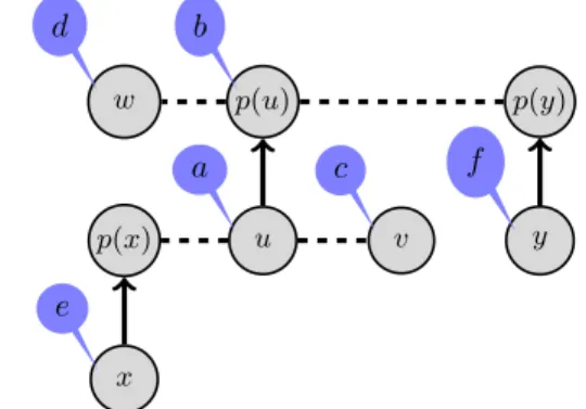
In the time slot and channel assignment problem, two conflicting nodes prevent a node from receiving a data or an acknowledgment intended for it when they use the same channel during the same time slot. Assuming that immediate acknowledgment is used at the MAC level: each unicast data packet is acknowledged in the slot it is sent, we determine two types of collisions: data-data and data-acknowledgment. Tak-ing into account that data sent by sensor nodes are collected by the sink using a routing tree, we can show that the only possible conflicts are those given by Property 1 and illustrated in Figure 2. In this figure, a solid line between two nodes means a radio link belonging to the routing tree. In contrast, a dashed line represents a radio link that is not used by routing. Property 1: For any node u, its conflicting nodes, when using the immediate acknowledgment, are:
a) node u itself,
b) node P arent(u), denoted p(u) in Figure 2, c) one-hop neighbors of u, see node v,
d) one-hop neighbors of P arent(u), see node w,
e) nodes whose parent is a one-hop neighbor of u, see node x,
f) nodes whose parent is a one-hop neighbor of P arent(u), see node y. u a p(u) b v c w d x e p(x) y f p(y)
D. Multi-interface sink
As most of the wireless sensor networks deployed support data gathering applications, the sink node is the destination of all the data generated in the network. Thus, in order to enhance the sink reception throughput, a sink with multiple radio interfaces, in short a multi-interface sink, is used. These multiple radio interfaces enable the sink to receive simultane-ously on different channels. It is useless to have a sink with a number of radio interfaces strictly higher than its number of children or the number of channels available, as confirmed by theory and experimental results [39].
E. Optimal number of slots in a collision-free schedule We first give some definitions related to schedules. Definition 1: A schedule is said to be valid if and only if in each time slot there is no node that:
• either transmits on the same channel or on the same radio interface more than once,
• or receives on the same channel or on the same radio interface more than once,
• or transmits and receives on the same channel or on the same radio interface.
Definition 2: A schedule is said to be collision-free if and only if no two conflicting nodes are assigned the same timeslot and the same channel.
Definition 3: A schedule is said to be traffic-aware if and only if each sensor node is assigned the minimum number of slots that enables it to transmit all its messages in the same slotframe.
Definition 4:A traffic-aware collision-free schedule is said to minimize data gathering delays if and only if in the absence of message loss, each message sent in a slotframe is delivered to the sink in the same slotframe.
Property 2: The delivery time of data in a collision-free schedule minimizing data gathering delays is bounded by one slotframe plus the duration of slots granted to data gathering. In the worst case, the data message is generated at the end of the slot granted to the node considered. Consequently, this message has to wait until the next slotframe. Since in the absence of message loss, the message is delivered to the sink in the same slotframe, the data message considered reaches the sink in the last slot of the slotframe. Hence the property.
Property 3: In a raw data convergecast, the minimum number of slots assigned to sensor nodes is lower bounded by max(Sn, St), with: Sn= d X u∈W SN Gen(u)/ge (2) St= Gen(c1) + 2 X v∈subtree(c1) v6=c1 Gen(v) + δ (3)
with g = min(ninterf, nchild, nchannel), where ninterf denotes the number of radio interfaces of the sink, nchild the
number of children of the sink, nchannel > 1 the number of available channels for the convergecast and δ = 1 if the (g + 1)thchild requests the same number of slots as the first
one, the children of the sink being sorted by decreasing order of slot demands, δ = 0 otherwise.
The proof of this property can be found in [39].
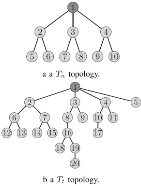
According to this property, we can define two types of topologies:
• Tn configurations where the minimum number of slots
is given by Equation 2. In such topologies, the requests are more uniformly distributed in all subtrees. Such a topology is illustrated in Figure 3(a).
• Tt topologies where the minimum number of slots is
given by Equation 3. In such topologies, the number of slots is imposed by the most demanding subtree. An example is depicted in Figure 3(b).
The minimum number of slots needed by a raw data convergecast is given in Table II, assuming that each node generates one data message per data gathering cycle.
a a Tn topology.
b a Tt topology.
Fig. 3: Examples of topologies. TABLE II: Minimum number of slots needed.
1 interface 2 interfaces 3 interfaces Topology 2 channels 2 channels 3 channels 2 channels 3 channels
Tt 19 13 13 13 13
Tn 9 6 6 6 5
Table II shows that with 2 channels the Tn configuration
considered needs only 6 slots with 2 radio interfaces instead of 9 slots with a single interface. Increasing the number of radio interfaces to 3 decreases the number of slots to 5 only if the number of channels increases to 3. The Ttconfiguration with
two channels requires 19 slots if the sink has a single interface and 13 slots with a sink equipped with 2 radio interfaces. Increasing either the number of channels, the number of interfaces or both to 3 does not bring any decrease in the number of slots.
As a consequence, it is useless to equip the sink with a number of radio interfaces strictly higher than the number of available channels or the number of the sink’s children.
Property 3 highlights the importance of building a routing tree where no subtree has slot request considerably higher than the average. A routing tree where all subtrees are balanced in terms of slot requests would require fewer slots to ensure data gathering.
Property 4: If nchannel ≤ ninterf < nchild and g × max(St, Sn) ≥Pu∈ W SNGen(u) + Rcv(ch), the
min-imum number of slots required for a raw data gathering in a multichannel WSN generating heterogeneous traffic is equal to max(St, Sn), with and without the immediate
acknowledg-ment, where Rcv(ch) denotes the number of packets received by ch, the child of the sink that receives the most.
The quantity g × max(St, Sn) denotes the number of
trans-mission opportunities available for the children of the sink. The number of messages that must be transmitted to the sink is equal toP
u∈ W SNGen(u). Each of these transmissions uses
an interface and a channel among the g available interfaces and channels. If nchannel ≤ ninterf < nchild, the only possibility for any child of a sink child is to transmit on a channel selected among the g channels. Hence, with the immediate acknowledgment policy, a conflict would occur with the child of the sink. To avoid such a conflict, we should have: g × max(St, Sn) ≥ Pu∈ W SNGen(u) + Rcv(ch),
where ch denotes the most receiving child of the sink. In such a case, the conflict is avoided and the number of slots is the same with and without immediate acknowledgment; it is equal to max(Sn, St). Hence, the property.
F. MAC dedicated to data gathering
In [16], the authors describe a centralized Tree-based Multi-Channel Protocol (TMCP) for data collection applications. It uses a fixed channel assignment approach for channel allocation. The whole network is partitioned into multiple sub-trees having the base station as a common root where each sub-tree is allocated a different channel. TMCP finds available orthogonal channels, partitions the whole network into sub-trees and allocates a different channel to each sub-tree. TMCP improves the throughput with regard to a single channel solution, while maintaining a high packet delivery ratio and low latency. However, TMCP blocks direct communications between nodes belonging to different sub-trees.
G. Multichannel routing for convergecast
In convergecast scenarios, where all the nodes send their traffic to one destination, namely the sink, it is useless to build routes to all destinations. It is sufficient to build a route from each sensor node to the sink. This routing tree is generally built using a gradient method: the sink broadcasts a message including a cost. A node receiving this message selects the transmitting node as parent if and only if it is the one-hop neighbor that provides the smallest cost. In such a case, the receiving node updates the cost before forwarding the message. The most famous example is given by the IPv6
Routing Protocol for Low-Power and Lossy Networks (RPL) [40]. Other examples exist such as MODESA, an optimized multichannel slot assignment for raw data convergecast in wireless sensor networks that combines neighborhood dis-covery and route building. A more detailed description of MODESA is given in Section IV.
A node may also select several potential parents. For instance, assuming that the cost is simply equal to the depth of a node, any node u 6= sink selects as its potential parents its one-hop neighbors (i.e. nodes with which it has a symmetric link) that have a smaller depth than itself. The depth of a node is recursively computed: the sink has a depth 0, its one-hop neighbors have a depth 1, etc. Notice that the depth of a node in a real multichannel network may differ from one channel to another.
The selection of potential parents may also take into account statistics about link quality. A potential parent with a high link quality is more frequently used to transfer application messages, as can be done in IEEE 802.15.4e TSCH networks [41].
H. Centralized versus distributed collision-free scheduling al-gorithms
Any collision-free schedule consists of a sequence of tu-ples (sender, receiver, channel, time slot) that is reproduced periodically. Finding a collision-free schedule with the min-imum number of slots has been proved NP-hard in a single channel network for arbitrary topologies [42]. That is why heuristics are generally used to compute time slot and channel assignment. This schedule can be computed in a centralized or distributed way. Centralized scheduling algorithms can reach the minimum number of slots, but do not scale. In contrast, distributed algorithms are able to support a large number of nodes but may be far from the optimal. Examples of centralized scheduling algorithms are given by TMCP [16], MODESA [23], whereas distributed algorithms can be illus-trated by DeTAS [43] and Wave [39].
We now evaluate the number of control messages needed by each of them, assuming a traffic-aware slot and channel assignment that minimizes the data gathering delays. We first observe that both the centralized and the distributed assignments use:
• Neighborhood Discovery, where each node discovers its neighbors and checks the symmetry of the links.
• Routing tree construction, where the routing tree used for data gathering is built by exchanging messages including the depth of the sending node. The depth of a node represents its distance to the sink, and this distance is expressed in number of hops.
In a centralized assignment, each node u 6= sink, whose depth in the routing tree is Depth(u) transmits the list of its neighbors, including its parent and its children in the routing tree, and its traffic demand Gen(u) to the sink. This message needs Depth(u) hops to reach the sink. We get a total ofP
AverageDepth · (N − 1) transmissions. Then, the sink computes the collision-free schedule and broadcasts it to all sensor nodes. Thus, the total number of messages required to establish the collision-free schedule in centralized mode is AverageDepth · (N − 1) transmissions + the transmissions to broadcast the Schedule to all nodes. Let us assume that the message including the Schedule must be fragmented into K fragments to be compliant with the maximum frame size allowed by the standard MAC protocol. Broadcasting the Schedule to all nodes requires K · (N − 1) messages in the worst case. Hence, the centralized assignment requires (AverageDepth + K) · (N − 1) transmissions.
In a distributed assignment, we assume that any node u uses T rans(u) as its priority for slot and channel assignment. Any node u computes T rans(u) according to Equation 1 and transmits it to its parent denoted P arent(u). This requires N − 1 messages to enable all nodes to know their own value of T rans(u), where N is the total number of nodes in the wireless sensor network. Any node u 6= sink should notify its priority first and then its slot assignment to its conflicting nodes. Hence, u notifies its slot assignment to its one-hop neighbors. This notification is forwarded by nodes that are parents and are one-hop away from u or P arent(u). Therefore the slot assigned to u needs 1 + V + V = 2V + 1 messages, where V denotes the average number of neighbors per node. Since we have N − 1 sensor nodes and each node notifies first its priority and then its slot assignment to its conflicting nodes, we need 2 · (2V + 1) · (N − 1) = (4V + 2) · (N − 1) messages to establish the collision-free schedule.
Hence, centralized assignment outperforms distributed as-signment in terms of the number of required messages if and only if: (AverageDepth + K) · (N − 1) ≤ (N − 1) · (4V + 2). Property 5: Centralized assignment requires fewer control messages than distributed assignment if and only if K ≤ 4V + 2 − AverageDepth, where V is the average number of neighbors per node and AverageDepth is the average of the depth of all nodes different from the sink and K is the number of fragments of the Schedule.
IV. SAHARA:AN EXAMPLE OF SOLUTION
The work described in this section is part of the larger SAHARA project.
A. Description of the solution proposed
We now present an example of a solution performing joint routing, time slot and frequency assignment and ensuring multihop synchronization by cascading beacons. A dedicated channel is used for signalling traffic. However, it should be pointed out that it can also be used by data traffic. Network connectivity is assumed to be ensured on this control channel. 1) A solution based on the IEEE 802.15.4 standard: The physical layer of the IEEE 802.15.4 standard has been adopted in many standards such as ZigBee [13], WirelessHART [44],
ISA100.11a [45]. It is based on a robust modulation that allows symbol redundancy and ensures good resiliency against multipath interference, which makes it convenient for indoor deployment. It offers 250 Kbps in the 2.4 GHz band and 16 orthogonal channels, making it a good candidate for multi-channel MAC protocols. This physical layer has therefore been adopted in the SAHARA project.
2) Network deployment: As previously stated, we tackle static deployments where nodes remain static once they have been deployed. The first node to be activated is the node in charge of creating the network and managing the time syn-chronization. This specific node starts signalling its presence using periodic beacon frames. The sink node can be chosen to play this role. The beacon frame will help other nodes to detect its presence when scanning on the specified control channel. When the other nodes are activated, they will detect the beacon and send a join request to the sink. Once a node is allowed to be part of the network (the network admission process is beyond the scope of this chapter) this node will propagate the beacon that it has received. In order to avoid collisions between beacon frames, the sink indicates in which order the beacons should be propagated. Thus, beacons are sent in a collision free TDMA manner where each node has its own slot for broadcasting the beacon frame. Nodes that are multiple hops away from the sink will send their join request in a multihop manner to reach the sink. Nodes are informed about the propagation order in the join response messages. In order for other nodes to update their propagation order, the beacon will include the updates during m consecutive beacon cycles (a beacon cycle is the period separating two successive transmissions of the beacon by the sink). Including updates and not the complete list of nodes enables this mechanism to be scalable. For more details about the beacon propagation mechanism, please refer to [46].
3) Slotframe: The slotframe describing the organization of node activities consists of four periods:
• a synchronization period that contains the multi-hop
beacon propagation, using the control channel.
• a control periodthat allows the transmissions of network control messages in CSMA/CA, using the control chan-nel.
• a data period that collects the applicative data accord-ing to a collision-free schedule. All available channels, including the control channel, are used.
• a sleep periodwhere all network nodes sleep to save node energy.
4) Multi-interface sink: To enhance the sink reception throughput, we use a multi-interface sink. Hence, the sink node is able to receive simultaneously on different channels. The number of radio interfaces of the sink is at most equal to the maximum between the number of available channels and the number of its children.
5) Neighborhood discovery: Neighborhood Discovery in a multichannel environment is done successively on each chan-nel belonging to the chanchan-nel list defined by the application. On the channel where neighborhood is being discovered, each
node broadcasts a Hello message containing the list of its one-hop neighbors. The sink initiates the Hello message cascade. The Hello messages are sent hop by hop from the sink to the farthest nodes of the network. Each node at a depth d receives Hello messages from its neighbors that are closer to the sink than itself and sends its own Hello message with a random jitter to avoid collisions. After several exchanges of Hello messages checking the symmetry of links, and if the neighborhood of the node is stable, each node sends a N otif y message to the sink. The N otif y message sent by node u 6= sink contains its depth, its neighborhood and some applicative information (e.g. the number of slots needed, the number of radio interfaces, etc.). The N otif y messages are processed by the sink acting as the entity in charge of computing the joint time slot and channel assignment.
6) Collision-free schedule: Since in our application, the condition of Property 5 is met, we use a centralized algorithm for a joint time slot and channel assignment, called Multichan-nel Optimized DElay time Slot Assignment (MODESA) [23]. The conflicting nodes and the potential parents of any node u 6= sink are computed from the collected one-hop neighbors, according to Property 1. The routes used for collecting data packets through the whole network are selected jointly with the channel and slot assignment.
During the initial discovery of channels, we want to reduce the latency of the first data gathering. That is why, just after the discovery of the first channel, a first schedule is built, making possible data gathering. The schedule is rebuilt each time a new channel is discovered to take advantage of par-allel transmissions. After that, any change in the information contained in the N otif y messages may cause updates in the current schedule or the creation of a new schedule.
In [47], the authors compare the cost of installing a central-ized schedule into the network using standards (CoAP, RPL, IPv6, IEEEE 802.15.4e) with the SAHARA solution. This cost is evaluated in terms of the number of packets sent in the network and latency. This cost is much higher when using the standards than with the SAHARA solution.
B. Illustrative example
We consider a network with eight nodes and three channels where, for the sake of simplicity, the topology is the same on all channels and is depicted in Figure 4. Each node ∈ {3, 4, 6, 7, 8} generates one data packet per slotframe, whereas nodes 2 and 5 generate two packets per slotframe. The sink, denoted node 1, has three radio interfaces.
For this network example, where AverageDepth = 1.57 and V = 3, the centralized assignment of time slots and channels outperforms the distributed assignment as long as K ≤ 12.43 fragments.
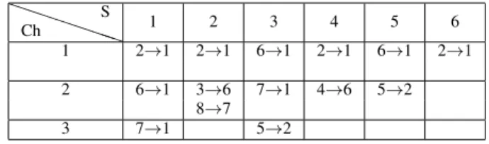
MODESA provides the schedule given in Table III. We observe that the three channels are simultaneously used in slots 1 and 3. The three sink interfaces are active in slot 1: they are receiving from nodes 2, 6 and 7. In slot 2, we notice spatial reuse on channel 2: nodes 3 and 8, that are 4 hops away, transmit simultaneously on the same channel.
1 2 3 4 5 6 7 8
Fig. 4: An example of topology.
TABLE III: The schedule obtained with MODESA for a sink with 3 radio interfaces and a network with 3 channels.
P P P P PP Ch S 1 2 3 4 5 6 1 2→1 2→1 6→1 2→1 6→1 2→1 2 6→1 3→6 7→1 4→6 5→2 8→7 3 7→1 5→2
C. Performance evaluation of the solution proposed
1) Impact of multiple channels and multiple radio interfaces on the aggregated throughput: We start by evaluating the ben-efits of using multiple channels and multiple radio interfaces on the sink node. We conducted simulations using the NS-2 simulator. Each point in the graphs represents an average of 100 repetitions generated with random topologies of 50 nodes. The size of the packets is 50 bytes. We compared the performance in terms of aggregate throughput calculated in terms of the number of packets received by the sink per second for different MAC protocols: HMC [29] the multi-channel MAC protocol for WSNs presented in Section II-I3, random allocation, a multi-channel MAC protocol that allocates chan-nels to node in a random fashion and “1 channel” that is standard CSMA/CA using a single channel. First, we show in Figure 5a the benefits of using multiple channels. Simulation results show that even allocating the channels in a random manner gives much better performance than using a single channel. HMC outperforms a random allocation because it takes into account the interference between neighbors. Figure 5b shows simulation results of the same protocols, but using 3 radio interfaces on the sink. Here we show the benefits of using multiple radio interfaces on the sink. The “1 channel” protocol is now a MAC protocol that uses one channel per radio interface of the sink. Results clearly show the enhancement on the aggregate throughput when we combine multiple channels with multiple radio interfaces on the sink.
In the following, we evaluate the performance of MODESA with regard to the Optimal scheduling on the one hand and TMCP, a relevant cluster-based multichannel scheduling, on the other hand. We recall that TMCP partitions the tree topology into multiple subtrees. The inter-tree interference is minimized by assigning different channels to subtrees. All the nodes in the same subtree communicate on the same channel. For TMCP, we set the priority of a node equal to its depth. We
a With multiple channels.
b With multiple channels and interfaces.
Fig. 5: Number of packets per second received by the sink.
assume that the number of channels is equal to the number of subtrees.
We distinguish two cases: a) homogeneous traffic, where all the nodes generate one packet per data gathering cycle, and b) heterogeneous traffic, where some sensor nodes generate several packets per data gathering cycle (i.e. nodes have different sampling rates).
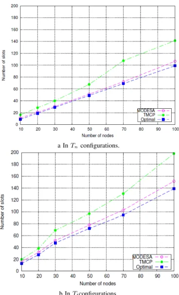
2) Homogeneous traffic and sink with a single radio inter-face: In the first set of simulations, we assume homogeneous traffic and a sink equipped with a single radio interface. We compare the number of slots needed to complete the convergecast, the number of buffers required, and the slot reuse ratio. The results are presented in Figures 6 and 7. Overall, the performance of MODESA is better than TMCP. Taking a closer look at the results plotted in Figure 6, we find that in configurations with 100 nodes, MODESA uses respectively 20% fewer slots in Tt configurations (23% in
Tn configurations) than TMCP. This agrees with the
eval-uation results in Figure 7b, where our joint channel and time slot assignment achieves a higher slot reuse ratio than TMCP. Moreover, the drift of MODESA from the optimal is still within 9% in Ts configurations (respectively 7% in Tn
configurations) as depicted in Figure 6. Furthermore, TMCP requires more buffers than MODESA: in 100-node topologies, MODESA needs only 15 buffers while TMCP requires 44
buffers, as illustrated in Figure 7a. This can be explained by the fact that MODESA takes into account the number of packets in the buffers when it schedules nodes.
a In Tnconfigurations.
b In Ttconfigurations.
Fig. 6: Number of slots used by TMCP, MODESA and Optimal.
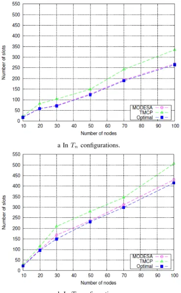
3) Impact of the number of radio interfaces of the sink: To further study the behavior of MODESA and TMCP, we conducted simulations where the sink is equipped with a number of radio interfaces equal to the number of subtrees. Each radio interface operates on a different channel, so the sink can receive simultaneously from its children. We always assume that each node generates one packet per data gathering cycle.
Figure 8 shows the same behavior of curves as seen in Figure 6. For small topologies (≤ 30), MODESA and TMCP are close. But when the number of nodes increases, the gap between the algorithms becomes huge. These results unam-biguously display the excellent performances of MODESA in schedule length.
a Buffers for TMCP and MODESA.
b Slot reuse by TMCP and MODESA.
Fig. 7: Buffers needed and slot reuse by TMCP and MODESA.
4) Impact of additional links: A frequent assumption in al-gorithms computing collision-free schedules for data gathering applications is that all interfering links that do not belong to the routing tree have been eliminated by a receiver-based channel assignment. However, it was proved in [49] that assigning a minimum number of channels to receivers such that all interfering links are removed is NP-complete. It is important to note that MODESA does not require all interfering links to be removed. MODESA easily takes into account the presence of additional interfering links, as illustrated by the following example. We consider the topology depicted in Figure 9, where the routing tree is depicted in solid lines, whereas the additional interfering links are depicted in dotted lines. The sink has a single radio interface and each node generates one packet per data gathering cycle. On each link of the routing tree, the notation slotichannelj means that there is a
transmission on this oriented link in slot i and on channel j. If on the link considered, several transmissions are needed,
a In Tnconfigurations.
b In Ttconfigurations.
Fig. 8: Number of slots used by TMCP, MODESA and Optimal with multiple radio interfaces.
they are separated by a semicolon. Table IV summarizes the number of slots required by MODESA.
TABLE IV: Number of slots needed by MODESA.
sink with a single interface
1 channel 1 channel 2 channels no additional link additional links additional links Depicted in Figure 9(a) Figure 9(b) Figure 9(c)
Slots 9 11 9
In the absence of additional links, 9 slots are needed to complete convergecast. However, when additional interfering links are added, 2 extra slots are required. Adding an addi-tional channel for scheduling re-establishes the initial schedule length because more parallel transmissions are allowed.
To further investigate the impact of interfering links on schedule length, another set of simulations was conducted. In the results presented below, the sink is equipped with a number of radio interfaces equal to its number of children. The
a Case a).
b Case b).
c Case c).
Fig. 9: Topology considered with additional links.
number of channels is equal to the number of radio interfaces. Additional links are added: for each node at even depth d in the tree, an additional link is generated with a node at depth d − 1 different from its parent. Furthermore, with a probability equal to 0.5, another link is added with a node of depth d + 1 different from its children. On average, 60% additional links are added. As can be seen in Figure 9, the impact of additional links depends on the routing tree. The worst routing trees are Tt ones for both MODESA and TMCP. For 100 nodes,
MODESA needs 13 additional slots to complete convergecast in Tt configurations, while only 5 slots are needed in Tn
configurations. It is also worth noting that, for MODESA, the number of additional slots due to additional links is smaller than for TMCP. This shows the capacity of MODESA to easily incorporate the additional conflicting links.
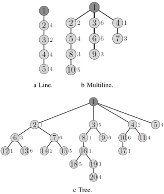
5) Heterogeneous traffic: In this second series of simula-tions, the sink is also equipped with as many radio interfaces as children. We first consider the three topologies depicted in Figure 10, where the number beside the node represents the number of messages generated locally by the node considered. For all these topologies MODESA is optimal requiring the minimum number of slots, as illustated in Table V. However, TMCP needs more slots in all these topologies. In addition, for the multiline and tree topologies, MODESA needs only two radio interfaces and two channels to reach the optimal
a Line. b Multiline.
c Tree.
Fig. 10: Topologies with heterogeneous traffic. TABLE V: Number of slots needed by Optimal, TMCP and MODESA.
Line Multiline Tree 1 int. 1 channel. 3 int. 3 channels 4 int. 4 channels Optimal 24 26 45 MODESA 24 26 45
TMCP 32 34 58
number of slots to complete convergecast. However, TMCP, even when the sink is equipped with 3 or 4 radio interfaces, does not achieve the optimal values. This can be explained by the fact that scheduling all the nodes of the same subtree on a single channel cannot ensure a high spatial reuse ratio.
The results depicted in Figure 11 show again that MODESA is close to the optimal values of slot numbers: the distance is 5% in Tt configurations (respectively 3% in Tn
configura-tions). In addition, MODESA obviously outperforms TMCP. D. Robustness and Adaptivity of the solution proposed
The solution proposed supports any network topology that is connex on the control channel. The topology may vary from one channel to another. For reliability reasons, a mesh topology is chosen. Hence, each node is able to cope with link or node failure of its preferred parent by selecting another one from its potential parents.
Additional links, that are not used in the routing graph, may exist. These links may add interferences that are avoided by our solution. The number of radio interfaces of the sink is a parameter that may vary. To cope with transmission errors, the number of slots granted to each node is higher than the