HAL Id: hal-01658947
https://hal.uca.fr/hal-01658947
Submitted on 11 Jan 2018
HAL is a multi-disciplinary open access archive for the deposit and dissemination of sci-entific research documents, whether they are pub-lished or not. The documents may come from teaching and research institutions in France or abroad, or from public or private research centers.
L’archive ouverte pluridisciplinaire HAL, est destinée au dépôt et à la diffusion de documents scientifiques de niveau recherche, publiés ou non, émanant des établissements d’enseignement et de recherche français ou étrangers, des laboratoires publics ou privés.
Mechanical testing of coarse soils with large direct shear
box
Bastien Chevalier, Gaelle Baudouin, Gaël Godi, Claude Bacconnet, Pierre
Breul
To cite this version:
Bastien Chevalier, Gaelle Baudouin, Gaël Godi, Claude Bacconnet, Pierre Breul. Mechanical testing of coarse soils with large direct shear box. Eurofuge 2016 - 3rd European Conference on Physical Modelling in Geotechnics, Jun 2016, Nantes, France. �hal-01658947�
1 INTRODUCTION
The shear strength properties of soils are constantly used for calculation of earth works, either with analytical methods or numerical methods. These parameters are classically obtained from laboratory model tests such as direct shear tests or triaxial compression tests. These tests usually give a value of internal friction angle and cohesion, where appropriate, used to described the behavior of soils based on Mohr-Coulomb failure law
The determination of these mechanical properties for coarse granular soils represents an important question in geotechnical engineering in terms of site investigation, design, survey and maintenance of earth works. But for obvious reason of particle size of the material compared to apparatus size, it is not possible to use classical testing machines.
Coarse soils cannot be tested in classical apparatus that are usually of maximum dimension 100 mm. Testing coarse materials thus require to eliminate the biggest particles but this cannot be done without changing the mechanical behavior of the material, as soon as the coarse fraction exceeds some threshold (Fragaszy, 1992). Consequently, one other way is to use large testing apparatus so that it increases the size of the maximal particle size that can be tested. Cerrato (2006) showed that the size of shear box has an influence on the measured properties of soils. Simoni and Houlsby (2006) used a large shear box for testing shear strength and dilatancy of mixtures of sand and gravel.
The paper presents the specifications of a large direct shear box which was developed in the Eco-grafi laboratory of Institut Pascal. The apparatus is
ten times bigger than classical shear boxes and the range of materials that can be tested is widened.
The results of shear tests conducted on three coarse granular materials are presented. The effect of shear rate and initial compaction is presented, as well as test repeatability.
2 SHEAR BOX SPECIFICATIONS
The shear box has a square shearing plane of 0.60 m x 0.60 m, and the sample of material is 0.40 m thick. Based on French standard for shear test (AFNOR, 1994), the maximal particle size that can be tested in the device is about 50 mm.
The confining stress is applied on the top of the sample by a rigid steel plate articulated on a vertical actuator with sensor (Fig.1). The upper half of the sample is maintained fixed in the horizontal plane by two horizontal force sensor, which measure the total shear force (Fig.2). The lower half of the sample is pushed horizontally by a second actuator, at a constant shear rate.
The vertical actuator is used for both sample compaction in the preparation phase and sample confining in the shear test phase. The maximal confining force is of, 200 kN, i.e. confining stress of, 555 kPa. The maximal shear force is of 175 kN, i.e. a maximal shear stress of 485 kPa, calculated on a plain shear plane.
The shear rate is controlled with the horizontal actuator and can be fixed between 0.01 mm/s to 0.16 mm/s.
Mechanical testing of coarse soils with large direct shear box
B. Chevalier, G. Baudouin, G. Godi, C. Bacconnet & P. Breul
Clermont Université, Université Blaise Pascal, Institut Pascal, BP 10448, F-63000 Clermont-Ferrand, France.
CNRS, UMR 6602, Institut Pascal, F-63171 Aubière, France.
ABSTRACT: Direct shear test is a very classical laboratory test widely used in soil mechanics and geotechnical engineering. This paper presents results of direct shear tests conducted with a large shear box presenting a square shearing plane of size 0.60 m x 0.60 m. Based on standard requirements for small shear box, the maximal particle size of tested material can be up to 50 mm. The effect of shear rate and compaction of the material on the results were tested on a gravel of particle grading ranging from 0 mm to 31.5 mm. Tests on two other coarse materials are presented: compressed clay pellets and light expanded clay beads.
Figure 1. Diagram of the large shear box (1) placed in a rigid steel frame ready for testing, with horizontal actuator (2) enabling shear displacement and vertical actuator (3) for confining the sample with rigid steel plate.
Figure 2. Detailed view of the shear box, showing lower box, moved by actuator and upper box, maintained fixed by force sensors.
The friction between upper and lower box is reduced by a play of few millimeters between both boxes by mean of four screw located on each corner of the box.
Volumetric strains are quantified by the vertical displacement of the top plate, which is measured with three LVDT sensors located at fixed locations on the top plate. It enables to calculate the mean vertical displacement of the top plate as well as its rotation angle about the direction of shearing and the perpendicular direction. Only the top plate rotates, due to sample deformation during the test. The upper half box can only translate horizontally.
3 TESTS ON A GRAVELY SOIL
We tested a gravel commonly used in roadway structures and embankments, called gravel 0/31.5 based on the range of diameters of its grains, given in millimeters. The specifications of the gravel are given in the European standard EN 13285. The grain size distribution curve of the gravel 0/31.5 is given on Fig.3. Figure 4 shows a picture of the gravel soil.
The samples of gravel soil were all prepared by compacting three successive layers of material with a normal force of 36 kPa (i.e. a normal stress of 100 kPa), maintained during 30 seconds.
Figure 3. Particle size distribution of the gravel soil
Figure 4. Picture showing the aspect of the gravel soil.
3.1 Effect of shear rate
First, the influence of shear rate on the test result is presented. Two successive tests were performed
on the gravel soil with same initial conditions of density. Both samples were confined with a confining force N of 36 kN, corresponding to an confining stress of, 100 kPa. First sample presented a density of 1658 kg/m3 and was sheared at a rate of, 0.05 mm/s; second sample with a density of, 1648 kg/m3, was sheared at a rate of, 0.20 mm/s.
Figure 5 shows the results of both tests, in terms of shear force and normal displacement versus shear displacement.
Then, a series of three tests was conducted on samples of gravel with a confining stress for shear test of resp. 100, 200 and 400 kPa (i.e. normal force of resp. 36, 72 and 144 kN).
Figure 5. Shear force and normal displacement versus shear displacement for 2 value of shear rate: 0.05 and 0.20 mm/s, conducted on the gravel soil with a confining force of 36 kN corresponding to an confining stress of 100 kPa.
The results presented on Fig. 5 show that there is no significant effect of the shear rate in the range tested and for this material. In addition, we can see that for same initial conditions, the results are very similar in terms of shear force as well as vertical displacement.
3.2 Effect of confining stress
The same material was then tested with three values of confining stress, on samples of same initial density. The samples were prepared in three layers, each layer being compacted in static conditions with a force of 36 kN (i.e. 100 kPa). The final density of the samples was of, 1627 ± 9 kg/m3.
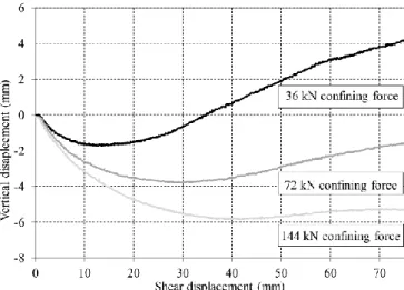
After the preparation, the samples were confined with a confining force N of resp. 36, 72 and 144 kN (resp. 100, 200 and 400 kPa) and then sheared with a rate of 0.05 mm/s. Figure 6 and 7 resp. shows the results obtained in terms of shear force and vertical displacement respectively versus shear displacement.
Based on the previous results, a direct shear peak friction angle φpeak,ds was calculated for each test
from maximal normalized shear force. The vertical displacement v was related to shear displacement u to calculate a rate of dilation dv/du. The dilation angle ψ was calculated from the equation
u v
d d
tan (1)
Figure 6. Shear force versus shear displacement for confining forces of, 36, 72 and 144 kN (i.e. 100, 200 and 400 kPa) for the gravel 0/31.5 at a void ratio of 0.66 ± 0.01.
Figure 7. Vertical displacement versus shear displacement for confining forces of, 36, 72 and 144 kN (i.e. 100, 200 and 400 kPa) for the gravel 0/31.5 at a void ratio of 0.66 ± 0.01.
The detailed results of the tests on gravel soil are summarized in Table 1.
As the confining stress increases, we observed a decrease of the peak friction angle and the dilation angle as well as an increase of the relative displacement at which peak occurs. These observations are consistent with classical behavior of dry cohesionless soils (Lambe and Whitman, 1969).
The critical state friction angle φcv,ds represents
the minimal shear strength that can be mobilized by a granular material and is obtained when the material shears with constant volume. The shear displacement was not sufficient to reach the critical state.
Table 1. Test results on gravel soil 0/31.5. __________________________________________________ density (kg/m3) 1619.6 1624.5 1638.2 e0 (-) 0.662 0.667 0.648 N (kN) 36 72 144 σ’ (kPa) 100 200 400 __________________________________________________ (τ/σ’)peak (-) 1.106 1.044 0.992 upeak (mm) 39.3 50.2 46.4 φpeak,ds (°) 47.9 46.2 44.8 ψ (°) 7.0 3.9 1.6 __________________________________________________
4 TESTS ON MARGINAL COARSE MATERIALS
4.1 Tests on compressed bentonite pellets
A series of tests was performed on compressed clay pellets. This is an industrial material composed of bentonite clay, and used for its ability to expand drastically in presence of water. This material can be used in the drilling industry or for creating impermeable joints.
The shape of the pellet is quasi-spherical, as shown on Fig. 8. The size distribution of the pellets is monodisperse. The density of the pellet is of 2300 kg/m3. Compression tests were conducted on pellets in the directions 1 and 2 (Fig.8). A maximal compression force of 976 ± 158 N in direction 1 and of 1116 ± 119 N in direction 2 were obtained.
Figure 8. Detailed view of one pellet of compressed bentonite
Figure 9 and 10 show the results obtained resp. in terms of shear force and vertical displacement respectively versus shear displacement on clay pellet samples of void ratio of 0.871 ± 0.020. Table 2 summarizes the detailed results of the three tests.
The results show a decrease of the peak friction angle and dilation angle with the normal stress. However, it can be noticed that when the confining stress increases, the fraction of crushed pellets after the test also increases from 8 % for a normal stress of 50 kPa to 34% for a confining stress of 150 kPa. The decrease of dilation angle has to be related with the relatively weak compression strength of pellets and the crushability of the material.
Figure 9. Shear force versus shear displacement for confining forces of, 18, 36 and 72 kN (i.e. 50, 100 and 200 kPa) for the compressed clay pellets at a void ratio of 0.871 ± 0.020.
Figure 10. Vertical displacement versus shear displacement for confining forces of, 36, 72 and 144 kN (i.e. 100, 200 and 400 kPa) for the compressed clay pellets at a void ratio of 0.871 ± 0.020.
Table 2. Test results on clay pellets. __________________________________________________ density (kg/m3) 1222.1 1222.1 1244.9 e0 (-) 0.882 0.882 0.848 N (kN) 18 36 72 σ’ (kPa) 50 100 200 __________________________________________________ (τ/σ’)peak (-) 0.835 0.723 0.660 upeak (mm) 22.0 29.1 39.2 φpeak,ds (°) 39.9 35.9 33.4 ψ (°) 10.1 6.5 –4.6 crushed (%) 8 14 34 pellets __________________________________________________
4.2 Tests on expanded clay beads
Shear tests were also performed on expanded clay beads which is a light and easily crushable material: (Fig.11). This material is commonly used to reduce the weight of soil works on soft soils for example. The particle sizes range from 10 to 20 mm, for a density of 330 kg/m3 and the friction angle given by the manufacturer is of, 35 °. The maximal vertical stress recommended in the product specifications is of, 100 kPa. Three direct shear tests were performed with confining stress values under this limit: 25, 50 and 75 kPa (i.e. confining forces of resp. 9, 18 and 27 kN).
Figure 11. View of the expanded clay beads
Figure 12 and 13 resp. shows the results obtained in terms of shear force and vertical displacement respectively versus shear displacement on expanded clay beads samples of void ratio of 0.700 ± 0.053. Table 3 summarizes the detailed results of the three tests.
Figure 12. Shear force versus shear displacement for confining forces of, 9, 18 and 27 kN (i.e. 25, 50 and 75 kPa) for the expanded clay beads at a void ratio of 0.700 ± 0.053.
Figure 13. Vertical displacement versus shear displacement for confining forces of, 9, 18 and 27 kN (i.e. 25, 50 and 75 kPa) for the expanded clay beads at a void ratio of 0.700 ± 0.053.
Table 3. Test results on expanded clay beads.
__________________________________________________ density (kg/m3) 191.3 201.3 190.1 e0 (-) 0.725 0.639 0.735 N (kN) 9 18 27 σ’ (kPa) 25 50 75 __________________________________________________ (τ/σ’)peak (-) 1.211 1.070 0.957 upeak (mm) 52.5 72.7 80.9 φpeak,ds (°) 50.4 46.9 43.7 ψ (°) 9.1 2.3 –0.9 __________________________________________________
The results show once again a decrease of the peak friction angle and dilation angle with the normal stress. It can be assumed that as for clay pellets, the crushability of the material can explain the very low values of dilation angle, tending to 0.0 and slightly below. Contrary to the clay pellet, the volume fraction of damaged beads could not be quantified.
The value of the peak friction angles measured are greater than the friction angle value given by the manufacturer of the expanded clay beads.
5 CONCLUSION
Mechanical properties of coarse granular materials, being natural or industrial, can become a problem as soon as the maximal particle size is not compatible with usual testing apparatus anymore.
The development of large shear boxes is then important in order to be able to characterize coarse granular materials with best accuracy and without changing the particle grading curve of the material.
A large shear box was developed to test a wide range of materials with a maximal particle size of 50 mm and presenting a square shear plane of size 0.60 m x 0.60 m. A wide range of normal stress 25 to 500 kPa can be developed with the apparatus.
Series of direct shear tests were performed on several granular material with this large shear box. A gravel soil and two marginal industrial materials were tested: compressed bentonite pellets and expanded clay beads.
the effect of shear rate showed no influence on the mechanical behavior in the range tested. The repeatability was very good on these tests,
the effect of confining stress was consistent with results obtained by other authors, in particular the decrease of peak friction angle and dilation angle with the increase of normal stress,
the effect of the crushability of the compressed clay pellets and expanded clay beads was observed with respect to the normal stress, and through peak friction angle as well as dilation angle.
The critical state could not be obtained clearly on the presented tests and further developments of the testing apparatus should be made in order to capture the mechanical behavior in a wider range.
6 ACKNOWLEDGEMENTS
The development of the test apparatus presented in this paper was made within the framework of the project EcoGraFi, which received funding from the European Union.
7 REFERENCES
AFNOR. 1994. NF P 94-071-1, Soil investigation and testing; Direct shear test with shearbox apparatus; Part 1: Direct shear. 16 p.
AFNOR. 2010. EN 13285, Unbound mixtures; Specifications. Cerato, A and Lutenegger, A.J. 2006. Specimen size and scale
effects of direct shear box tests of sands. Geotechnical
Testing Journal, 26(6): 1-10.
Fragaszy, R. J., Su, J., Siddiqi, F. H. and Ho, C. L. 1992. Modeling strength of sandy gravel. Journal of Geotechnical
Engineering, 118(6): 920–936.
Lambe, T.W. and Whitman, R.V. 1969. Soil mechanics. John Wiley and Sons, New York.
Simoni, A. and Houlsby, G.T. 2006. The direct shear strength and dilatancy of sand–gravel mixtures. Geotechnical and