Data Communications Via Cable Television Networks:
Technical And Policy Considerations
by
Deborah Lynn
Frin
B.S.E.E., University of California at Berkeley (1980)
Submitted
in partial fulfillment
of the requirements for the
degree
of
Master of Science
at the
Massachusetts Institute of Technology
August 1982
© Massachusetts Institute of Technology 1982
Signature of Author ..
Technology Policy Program,
Department of Electrical Engineering and Computer Science
May 7, 1982
Certified by...
C
Thesis Supervisor
Certified by
S;/'Accepted by ...
U)
Thesis Supervisor
Department Head, Technology Policy Program
1
Archives
MASSACHUSEfTS INSTITUTEOF TECHNOLOGY
Data Conmmunications Via Cable Television Networks:
Tiechnical And Policy Considerations
by
D)cborah Lynn Estrin
Submitted to the
Technology Policy Program,
Department of Electrical Engineering and Computer Science,
on May 7, 1982 in partial fulfillment of the requirements
for the Degree of Master of Science
Abstract
Cable television networks offer peak communication data rates that are orders of magnitude greater
than the telephone local loop. Although one-way television signal distribution continues to be the
primary application of cable television systems, the cable television network can be used for two-way
data communications.
Data communication places severe engineering demands on the performance of a cable television
network. Therefore, to ensure that data communications capabilities are not precluded by poor
engineering, local cable authorities and the cable industry must identify and overcome the technical
barriers to the application of cable television networks to data communications. We identify the
following as the primary technical requirements that remain to be addressed by the cable industry:
-
Methods for controlling the accumulation of insertion noise and ingress on upstreimr
channels.
-
Reliability and security mechanisms to provide adequate levels of system availability,
overall quality of service, and privacy of communications.
-
System engineering that supports data communications among many nodes, other than
on a point-to-point basis.
If the cable industry applies tie resources necessary to satisfy these requirements, cable television
networks can gain a lucrative share of the growing residential and institutional, data communications
and information services markets, in competition with telephone company and cellular microwave
services.
users and service providers, local cable authorities, in addition to the cable industry, should establish
structural mechanisms to eliminate the cable operator's potential conflict of interest between its
carriage and content functions, which might otherwise inhibit this diversity.
The nature of
appropriate regulatory imechanisms has been a source of conflict and confutsion because of the
unclear status of the cable operator as broadcaster or common carrier. I.eascd channel access
requirements, which enforce limited separations on a channel by channel basis, can allow the
operator to serve in both capacities, thereby both encouraging investment in ftcilities and limiting the
opportunities for anti-competitive practices. The rate structures and levels adopted by the operator
will determine the extent to which leased channel access successillly achieves this end.
More than in the past, cable authorities will find themselves monitoring and specifying details of the
network infrastructures, both technical and operational, to ensure that suitable facilities are
constructed and that a diversity of service sources are granted access to the medium. This thesis is
intended as a resource for cable authorities, as well as cable operators, as they establish the role of
cable television networks in the data communications market. In particular, Chapter 6 serves as a
guide for city and state cable authorities to incorporate the technical detail and regulatory structures
necessary for data communication services into existing cable policy.
Thesis Supervisor: Dr. Jerome 11. Saltzer
Title: Professor of IElectrical Engineering
Thesis Supervisor: Dr. Marvin A. Sitbu, Jr.
Acknowledgments
I wish to thank my two thesis advisors, Prof. Jerry Saltzer and I)r. Marvin Sirbu.
Jerry Saltzer made it possible for me to pursue my technical interests, in addition to my non-technical
ones, by welcoming me into tie Computer Systems Research Group of the MIT'r Laboratory for
Computer Science. His pointed and constructive criticisms, tempered with encouragement and
enthusiasm, were priceless.
In addition to invaluable input to the development of this thesis, Marvin Sirbu gave an inordinate
amount of his time to the review, and revision of ithe first draft. IHe served as a model for integrating
technical and policy research.
I also wish to thank the EECS department for awarding me thdie Vinton Hlayes Fellowship in support
of my communications-research activities.
I am exceedingly grateful to Josef, my husband, who believed in me and in my efforts, and to my
parents, Thelma and Gerald, who taught me the confidence needed to begin and complete this task.
Table of Contents
Chapter One: Introduction
11
1.1 Motivations and applications
11
1.1.1 The markets
12
1.1.2 Proposed services
14
1.1.3 Existing applications
16
1.2 A possible scenario
17
1.3 Overview of this report
17
Chapter Two: Cable Television as a Data Transmission Medium: Tutorial
20
2.1 Cable system components 21
2.1.1 Basic cable systems 21
2.1.1.1 Hleadend equipment 21
2.1.1.2 Cable distribution plant -- cable, amplifiers, bridging amplifiers 23
2.1.1.3 Interface equipment
25
2.1.2 'l'wo-way cable system components 26
2.1.2.1 Ileadeiid 26
2.1.2.2 Cable distribution plant 27
2.1.2.3 Interface units 28
2.2 Access schemes and communication protocols for two-way data communications 29
2.2.1 Decscription of access schemes * 29
2.2.1.1 Polling 29
2.2.1.2 FDM 30
2.2.1.3 TDM 31
2.2.1.4 Contention schemes 32
2.2.2 Performance characteristics of access schemes 34
2.2.2.1 T'hroughput
34
2.2.2.2 Connectivity
34
2.2.2.3 System availability
35
2.2.2.4 Relative costs of access schemes
36
2.3 Cable system limitations
37
2.3.1 Noise and corrective measures 38
2.3.1.1 Insertion noise 38
2.3.1.2 Ingress 40
2.3.1.3 Corrective measures 41
2.3.2 Reliability 43
2.3.2.1 System reliability 43
2.3.2.2 Security and privacy 45
2.3.2.3 Institutional roadblocks to system reliability 46
Chapter Three: Cable Television as a Data Transmission Mediunm: Analysis
3.1 Impediments to Data Service I)cvelopment
48
3.2 Service Structure Options 49
3.2.1 Conventional Residential Systems -- I
[eadend
to Subscriber 503.2.1.1
One-way
Systems
50
3.2.1.2 ''wo-way Systems 51
3.2.2 MNultiple Server Residential Networks 51
3.2.2.1 Institutional requirements 52
3.2.2.2 Tcchnical requirements 53
3.2.3 lHybrid Residential Networks 55
3.2.4 Institutional Service -- Point-to-Point and Multipoint 57
3.3 Costs 57
3.3.1 Basic cable System Costs 58
3.3.2 Two-way Residential System Costs 59
3.3.2.1 Headend and Customer Premises E'quipment 60
3.3.2.2 Cable Plant 61
3.3.2.3 Operation and maintenance 62
3.3.3 Two-way Institutional System Costs 63
3.4 Prices 65
3.5 Summary 68
Chapter Four: Alternative media: telephone local loop and Digital Termination
69
Services
4.1 'l'lephone local loop 69
4.1.1 Circuit-Switched, Digital Capability 70
4.1.1.1 Costs 72
4.1.2 Data Above Voice (DAV) -- I~ocal Area Data Transport (LADT) services 72
4.1.2.1 Costs 74
4.2 D'ITS 75
4.3 Comparison 75
Chapter Five: Regulatory Issues
77
5.1 Introduction 77
5.2 Regulatory Jurisdiction 78
.... 5.2.1 Background 78
5.2.2 State and local regulation and federal preemption 80
5.2.3 The Local Franchising Process 82
5.3 Cable as Carrier and Broadcaster 83
5.3.1 Introduction 83
5.3.2 Content regulation 86
5.3.3 E-conomic regulation 87
5.3.4 Structural regulation 88
5.3.5 Leased channel access 91
5.4 Privacy -- Wiretapping, Intrusion, Misuse of Information 95
5.5 Summary 98
Chapter Six: Guidelines for municipal policies
99
6.1 Introduction
99
6.2 City goals and the role of data services 100
6.3 Entry points for municipal input 101
6.4 Community requirements 103
6.4.1 'l'cchnical requirements 104
6.4.1.1 Engineered for data
105
6.4.1.2 Addressability and access methods 107
6.4.1.3 Reliability and maintainability 108
6.4.1.4 Communication services 108
6.4.1.5 Interconnection 109
6.4.2 Operational requirements 109
6.4.2.1 Leased Access 110
6.4.2.2 System expansion 117
6.4.2.3 Separation of institutional and residential networks 118
6.4.2.4 Operator liability 118
6.4.2.5 Privacy 119
6.4.3 State policies 119
6.5 Summary 120
Chapter Seven: Conclusions
121
7.1 Network planning 121
7.2 Strategies for the cable industry 122
7.3 City policy
123
7.4 Suggestions for further research 124
Appendix A: Provider Industry Structure: Snapshot of the industry, January, 1982
126
A.1 Customer Premises Equipment Companies 126
A.1.1 Converter Manufacturers 126
A.1.1.1 E-Corn 127
A.I.1.2 Control-Corn 127
A.1.1.3 Tocom 128
A.1.1.4 Pioneer 129
A.1.1.5 Jerrold 129
A.1.1.16 Oak Industries 129
A.1.1.7 Scientific Atlanta 129
A.1.2 Modem Manufacturers 130
A.1.2.1 Mitre 130
A.1.2.2 Local Data D1istribution 130
A.1.3 Local Area Computer Network Vendors 131
A. 1.3.2 Amdax
135
A.1.3.3 Wang
135
A. 1.3.4 Interactive Systems/3M
135
A.2 Services
136
A.2.1 Cable Operators
136
A.2.1.1 Warner-Amex
136
A.2.1.2 COX Cable
137
A.2.1.3 Timencs Inc. -- Manhattan Cable 138
A.2.1.4 Rogers Cablesysterns 139
A.2. 1.5 Sammons Commu nications 140
A.2.2 T'ransaction Service Providers 140
A.2.3 Information Service Providers 141
A.2.4 Communication Service Providers 141
Table
of
Figures
Figure 2-1: Cable Network Components 22
Figure 2-2: Tree 'I'opology
25
Figure 2-3: lub T) opology 26
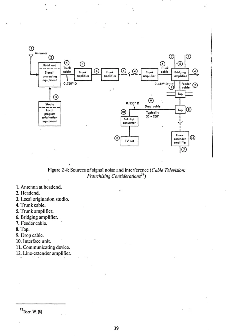
Figure 2-4: Sources of signal noise and interference 39
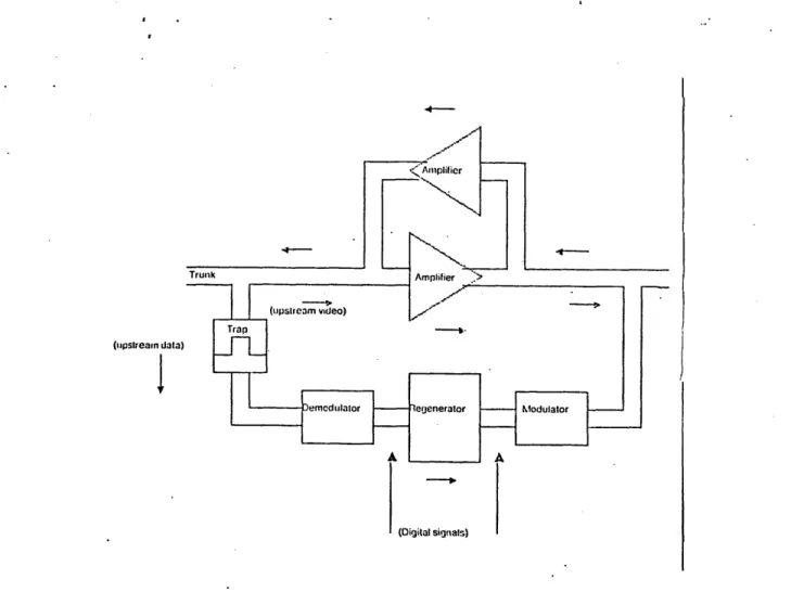
Figure 2-5: I)igital regenerator used to reduce upstream noise
42
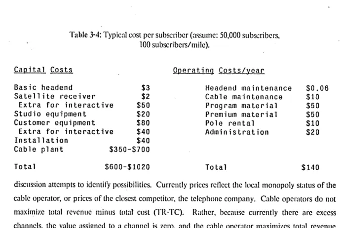
Figure 4-1: Circuit Switched iDigital Capability
71
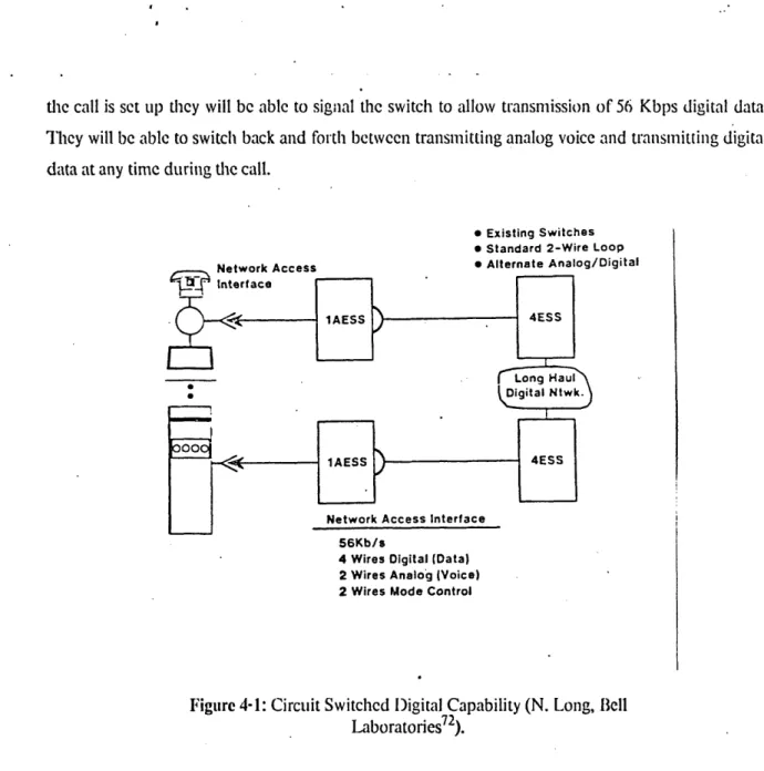
Figure 4-2: Local Area Data Transport
73
Figure 5-1: Warner Amex Code of Privacy
97
Table of Tables
Table 1-1: Some proposed interactive services for cable television
15
Table 3-1: Distribution plant component prices 58
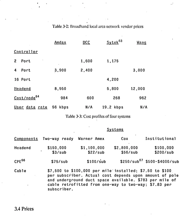
Table 3-2: Iroadband local area network vendor prices
65
Table 3-3: Cost profiles of four systems
65
Table 3-4: Typical cost per subscriber
66
Chapter
One
Introduction
Cable television networks
lwere designed to distribute television signals from a central location to
residential homes throughout a local region.
These
systems were used originally to provide
entertainment television to regions where over-the-air reception was not satisfactory. Increasingly,
they are used to provide a greater diversity of programs than over-the-air spectrum limitations
permit, and as a means of delivering premium television services
2.
Although one-way television signal distribution continues to be the primary application of cable
systems, the technology is also appropriate for two-way communications. This report focuses on
developments in two-way communications over city cable systems, in particular, two-way data
communuicalion services.
Data comnmunication places intense technical demands on the perfornmance of a cable television
network. Therefore, to ensure that data communications capabilities arc not precluded by poor
engineering, the city cable authority and the cable operator must identify and overcome the technical
barriers to the application of cable television networks to data communications. More than in the
past, the cable authority will find itself specifying details of the network infrastructures, both
technical and operational, to ensure that suitable facilities are constructed and that a diversity of
service sources are granted access to the medium.
1.1 Motivations and applications
This section sets the stage for our discussion of data communications via cable television networks. It
is not a rigorous survey of the market research in this area, but provides a sampling of envisioned
markets and applications. In so doing, we hope to communicate to the reader why data
1Also known as cable networks, or CATV (Community Antenna Television) systems. Throughout this report we will use the ternm "cable networks" interchangeably with "cable television networks" and "cable television systems".
communications via cable television networks is of interest to cities, residents, commercial and government users, and the cable industry.
1.1.1
The markets
There are two distinct markets for data communications: residential and instiitutonal. There are also
two categories of service: information and communication. Information services refer to those
services whereby a second party provides the content which is accessed, requested, or responded to
by the user. Communication services provide only the transmission and switching services, all
content is provided by the users independently of the communication service provider; users being
persons, organizations, computers, or other communicating devices.
The intracity market for business data communications already exists. Projections for its growth are based on the increasing use of computer equipnment within the office which will in turn generate
demand for increasing amounts of intracity communications. Currently, intracity communication
needs must be satisfied by the telephone company (see Section 4). intermittent demand for data
communications is satisfied by dial-up facilities at speeds up to 4800 baud. l)edicated facilities are
also available at speeds up to 56 Kbps. Point-to-point communications facilities are available at
higher speeds, but switched services are not. In the future, considerable demand is projected for high
speed switched networks which will accommodate ihtracity communications of both continuous and
intermittent natures. An institutional market for information services exists and is growing. Services
such as Lexus and Nexus
3will be spurred by the growth of standardized videotex services for the
business sector. These services will provide a common standard, or gateway, whereby users can
access many information sources.
Unlike the institutional market, the residential market for information services does not exist.
Projections for its growth are based primarily on projections of supply, rather than demand.
Although videotex is touted primarily as a home information service, it will grow as a mass media
service after it is established in the commercial sector [17].
Most existing residential data
communications demand currently takes the form of professionals working at home using terminals
and modems to talk to central computers and information services via phone lines. In addition,
increasing numbers of personal computers, used for both personal and small business applications,
are equipped with communications capabilities.
An informal random polling of 200 residents in a suburb of Boston which has a high concentration of professionals, resulted in approximately 3% who reported having terminals or personal computers in their homes4, another 13% reported having video games. In addition, the local cable operator estimates that approximately 25% of the homes passed will subscribe to pay-television. These numbers can be used as preliminary indicators of the size of the residential market. The number of residents with terminals indicates the minimum market size for data communic:ations to the home. Similarly, the number of residents with video games indicates the number of residents who tend to invest in "high technology" entertainment devices for the home. Finally, the number of pay-television subscribers probably indicates a short to medium-term upper bound on the existing residential market for data services.
Projections for future applications of residential data communications range from transaction and information services to electronic mail and multi-person games. Services such as
Teletext
and Videotex have received considerable press coverage, but the degree and form of their success is still uncertain. To a large extent it hinges on the development and availability of information providers and inexpensive terminal equipment.In 1981 there were 4,400 operating cable systems in the U.S. and an additional 2,000 that were approved but not yet built. These systems served approximately 10,400 communities and 17,200,000 subscribers, 22% of the T.V. households. The largest system had 188,880 subscribers5. Although most systems have 12 channels, systems constructed during the past 10 years have a minimum of 20 channels, and newly designed systems may have 50 or more channels [46]. Although there are wide variations, it is typical that half of the homes passed by the cable subscribe to it, and half of the subscribers purchase premium services such as pay-television6 .
4Survey conducted at M.I.T. Laboratory
for Computer Science, January through April. 1982. Supervised by Prof. J. Saltzer, and D. Estrin.
5
Cox Cable San Diego system.
6
1.1.2 Proposed services
In 1974
B1aer
et. al. [81 outlined a menu of possible applications for two-way cable systems, see Table 1-1.Baran also studied the applications of broadband information networks and suggested the following
categories of applications, many of which today appear farther off than they did eight years ago.
1. Work at home
- Person-to-person -- electronic mail.
- Secretarial assistance. - Access to company files.
2. Transaction services
- Banking services.
-Shopping.
-Price lists and information.
-Consumer advisory service.
3. General information access
- Newspaper.
- Fares and ticket reservations.
- Legal information.
- Library access.
4. Entertainment
- Games.
-Multiperson games.
Jones ct. al. outlined urban public services which rely upon telecommunications and would be well
suited to the use of broadband facilities. 1. Delivery of government services.
Subscriber Institutional Interactive instructional programs Computer data exchange Fire and burglar alarm monitoring Teleconferencing
Television ratings Surveillance of public areas Utility meter readings Fire detection
Control of utility services Pollution monitoring Opinion polling Traffic control
Market research surveys Fingerprint and photograph Interactive TV games identification
Quiz shows Civil defense communications Pay TV Area transmitters/receivers for Special interest group conversations mobile radio
Electronic mail delivery Classroom instructional TV Electronic delivery of newspapers Education extension classes
and periodicals Televising municipal meetings Remote calculating and computer and hearings
time sharing Direct response on local issues Catalog displays Automatic vehicle identification Stock market quotations Community relations programming Transportation schedules Information retrieval services Reservation services, ticket sales Education for the handicapped Banking services Drug and alcohol abuse programs Inquiries from various directories Health care, safety, and other Local auction sales and swap shops public information programs Electronic voting Business transactions
Subscriber originated programming Credit checks
Interactive vocational counseling Signature and photo identification Local ombudsman Facsimile services
Employment, health care, housing, Industrial security welfare, and other social Production monitoring
service information Industrial training Library reference and other Corporate news ticker
information retrieval services Telediagnosis
Dial-up video and audio libraries Medical record exchange
Videophone
aIt is unlikely that all of these services will be economically feasible on cable television networks. Some may not even be socially desirable. They have been compiled from various reports, FCC filings, corporate brochures, and advertising materials. Adapted from Baer,
Interactive Te Zlevision.
Table 1-1: Some proposed interactive services for cable television
(Cable Television: Franchising Considerations7)
2. Citizen-government interaction.
3. City administration.
4. Status monitoring.
1.1.3 Existing applications
Since the time when these applications were proposed, seven years ago, few of the visions have been
realized. Why does the application of cable networks to data communications seem any more viable
today? The primary reason is that today many of the services already exist but use different, narrower
bandwidth, higher cost, media such as telephone lines: connection of automated teller machines to
bantik
branch
offices, connection of terminals in urban and suburban schools to shared computer
facilitics, connection of airline reservation terminals to centralized data base facilities.
In fact, cable television technology is already in use as a data communications medium.
1. In the summer of 1981 New York City's Computer Service Center switched from phone
lines to Manhattan Cable Television (MCTV) facilities for communications with the
Manhattan municipal building. The switch reduced the city's data transmission cost by
approximately one third, from $30,000 to $20,0008
2. Financial institutions in Manhattan have been using MCTV facilities since 1975 to
connect Wall Street and Midtown offices.
3. Brown University in Rhode Island uses a broadband cable television network to
interconnect terminals and computers throughout the campus
94. In addition, information services are being used, if primarily by businesses:
a. In the United Kingdom, there is a two-way information service, Prestel, which uses
telephone lines to send information to and from users. Contrary to initial
expectations of the British Telecom which developed and offered the service, it is
used primarily by the business community.
b. In contrast to the videotex experience, the one-way teletext system now offered in
the U.K. appears quite successful among residentslo. 'lThis is attributable to lower
teletext access costs as well as the rather undeveloped nature of the information
provider services which therefore do not require the enhanced access features
offered by videotex.
c. Lexus and Nexus legal and medical data base services.
d. Dow Jones stock market information services.
8
Annual municipal data transmission costs for the City of New York are estimated to be $10,000,000.
9
Sytek Inc., LocalNct 20 system, see Appendix A.
10In a teletext system pages of information are "grabbed" from a constantly cycling data base of pages to simulate interactivity.
1.2 A possible scenario
In the short term cable operators will realize profits from institutional communication services, in
competition with the local telephone company. In the longer term, as information services and
inexpensive tennrinals become available, the residential market will also become important revenue
source. As was the case with the telephone, residential subscriber services will be spurred by the
desires of commercial users to reach consumers. Many of the first generation of information services
may only allow users to communicate with the headend and any services that reside there. l'o further
their growth, and increase subscriber penetration, cable operators will find it worthwhile to provide
for multiple server networks (see Section 3.2.2). As a result of these dcvclopments, infonnation services and communication services would be effectively merged. The cable operator would then offer communication services to both information and entertainments service providers and
communication users, and would itself act as one of the service providers ofi the network.
1.3 Overview of this report
If the cable television networks fulfill their potential as important, and unique, municipal resources, they should be made widely available to a diversity of users and service providers. Therefore, local cable authorities, in addition to the cable industry, should establish structural mechanisms to eliminate the cable operator's conflict of interest between its carriage and content functions, which might otherwise inhibit this diversity. In addition, data communication places intense technical demands on the performance of a cable television network. Therefore, to ensure that data communications capabilities are not precluded by poor engineering, local cable authorities and the cable industry must identify and overcome the technical barriers to the application of cable television networks to data communications.
The application of cable television facilities to data communications raises many questions regarding the proper implementation and operation of the facilities. In this report we address these questions, some of which are listed below:
-.Can data transmission be accommodated on existing cable networks?
-What engineering provisions must be made to handle two-way data transmission?
-What higher level communication protocols, such as addressing, should be implemented?
-Who should offer services?
-
Who should decide what services are to be offered, and how should it be decided?
- Is the cable operator acting as a broadcaster or a common carrier?
-
What regulatory or policy mechanisms are needed to achieve societal goals such as
protection of first amendment right to hear and speak?
- How will access to the cable network be charged for?
-What role should the local cable authority play in specifying technical and operational
details of the network?
-What must the cable industry do to prepare itself for offering these new services?
The first half of this report concentrates on technical issues
thatare not yet widely understood or
appreciated in the cable television community. In particular, the cable industry must develop the
expertise necessary for design and implementation of network facilities-and services; the city cable
authorities must understand the technology well enough to evaluate, and monitor network planning
and operation; ind the users and information providers, need to plan their applications according to
the existing, as well as potential, data communications capabilities of cable networks.
In Chapter 2 we present a tutorial on data communications over cable television networks, and in
Chapter 3 we analyze the associated costs, impediments, and service structure options. These
chapters should help the cable community better understand the technical issues and trade-offs
encountered in the design of data communications facilities and services. We find that the
communications protocols adopted largely determine the capabilities and performance of the system.
In particular, the ability to communicate with many other points on the network, i.e., not only the
headend, will be essential to future services. Performance is constrained by upstream noise and low
reliability which may result from poor system engineering and the relative inexperience of the cable
industry with data communications. In Chapter 4 we identify the unique properties of cable
television technology (e.g., an economical, high-bandwidth medium that accommodates broadcast
communications) by comparing it with other regional data distribution media (D)TS and telephone).
The second half of this report addresses the national regulatory and local policy issues associated with
the operation of data communications services via cable television networks. Chapter 5 outlines the
policy context and proposes how the regulatory framework of cable television might be most suitably
adapted to data communications applications. In Chapter 6 we integrate the technical and regulatory
details presented in earlier chapters. This chapter serves as a guide for city cable authoritics to
incorporate the technical detail and regulatory structures necessary for data communication services into existing cable policy. It emphasizes that not all two-way, cable, communications technologies are equally adequate for the full range of data communications applications and therefore, in addition to dictating operational policies, the cable authority must review the network design, proposed by the operator, to insure that suitable facilities are in place.
Chapter Two
Cable Television as a Data Transmission
Mviedium:
Tutorial
In this chapter we present a tutorial on the technical aspects of cable television networks as applied to two-way data communications. We review the hardware components of both traditional and enhanced cable networks and describe the communications protocols that can be brought to bear when implementing two-way data communication services. We conclude with a discussion of the primary technical limitations to implementation of two-way data communications. It is found that the communications protocol largely determines the capability and performance of the two-way system, given the limitations of upstream noise and low reliability.
Cable T'elevision systems, also referred to as Cable (Community Antenna Television, CATV) systems, were designed to distribute television signals from a central location to residential homes throughout a local region. These systems were used originally to provide entertainment television to regions where off the air reception was not satisfactory. Increasingly, they are used to provide a greater diversity of programs than spectrum limitations permit, and as a means of delivering pay-television.
Although one-way television signal distribution continues to be the primary application of cable systems, the technology is also appropriate for two-way communications. Two-way systems are those which carry signals from subscribers back to the headend (upstreami, in addition to distributing signals from the headend to subscribers (downslream).
The two-way data communication capabilities of cable technology have been most extensively exploited in private Local Area Communication Networks (LACN's). These networks transmit two-way video and data throughout large buildings, industrial plants, and campuses. This report focuses on developments in two-way data communications over city- wide cable systems, as opposed to
campus-wide systems.
entertainment programming to residential subscribers in rural, suburban, and urban areas. In
contrast, institutional networks are located in city centers and serve business needs ofcommnercial and governmental subscribers.l I Residential networks carry most of their traflic downstream in support
of their primary service, video entertainment. H-lowever, newer services, such as home security,
interactive videotex, and transaction services, require an upstream capability. Institutional networks, given their business clientele, will typically experience a more even distribution of communications to and from subscribers. Proposed institutional services include high speed two-way data
communications, in addition to closed-circuit television, for education and teleconferencing.
2.1. Cable system components
This section describes the elements which comprise a cable system.
The first part describes those
hardware components common to all cable systems. We then describe the additional hardware
necessary for the provision of two-way data communications.
2.1.1 Basic cable systems
All cable systems are composed of a headend, a distribution plant, and interface equipment. In a
traditional video distribution cable network,
thdie
headend receives over-the-air broadcasts and
translates them to frequency bands that are appropriate for transmission onto the cable plant.
Programming material that is prepared especially for cable is generated at the headend and is also
transmitted onto the cable plant. The cable distribution plant is a tree-like configuration
of
broadband coaxial cable, amplifiers, bridges, and feeder cables. The signals travel, via the
distribution plant, to the subscriber's home, where the interface equipment translates the signals into
a form receivable by the subscriber's television (Figure 2-1).
2.1.1.1 llcadend equipment
Cable systems were first built in the 1950's. to provide improved reception of television signals to
geographically obstructed or isolated areas. In this capacity, the system headend referred to the
location of the large receiving antenna from which the signals were transmitted onto the cable.
Trunk
Head Trunk --. . .--End Splitter TA 1 TA-2 ---- Foward 50 -300 MHz : . --. - Reverse 5 - 30 M HHz TA - Trunk Station IB -3IB - Intermediate Bridging Station ..----.. ... Feeder •F - eeder
P - Power inserter ,1 ..
BT -Bridging Trunk Station -b-- ibe .
-TB Terminating Bridging Station
LE Line Extender 6509
camera Power
Figur. 21 C l Nt rk Componnt (Scientific Atlanta Cable
LE-7Communications P oducts 1981 )
Today, in addition to traditional over-the-air broadcast signals, an increasing amount ofunk
programming material is received from -satellites.
Over-the-air signals are often translated from their original frequency to a part of the spectrum compatible with the rest of the cable system programming and the transmission characteristics of the cable. In addition to translation and retransmission, the headend equalizes the power levels of the incoming signals to minimize interference among the signals on the cable, and compensates for fluctuations in broadcast signals to insure that a noise-free, steady signal is transmitted onto the network. Some headends also phase lock the frequency offsets of incoming signals to reduce visual interference among them.
-2.1.1.2 Cable distribution plant
--
cable, amplifiers, bridging amnplifiers
The cable plant is comprised of broadband coaxial cable, signal anlplifiers, and bridging amplifiers.
All transmission over cable networks is 'requency DivisionMulliplexed
(IFDA), i.e., the totalfrequency spectrum of the cable is subdivided into channels. I'ach channel allocation is typically equal to a standard television channel, 6 Mhz. The bandwidth that can be transmitted over coaxial cable is largely determined by the amplifiers used. The cable itself has a bandwidth in the giga-Hz range but the active components, namely amplifiers, are limited in the bandwidth that they can transmit without causing excessive cross-talk 3
The amplifiers used on older cable systems transmit less than 300 Mhz which limits their carrying capacity to between 12 and 20 channels: these systems make up more than 50% of the cable systems in use today14. With appropriate engineering, newer systems, whose components transmit 300 Mhz, will carry up to 30, 6 Mhz (TV) channels; systems whose components transmit 400 Mhz will carry up to 52 TV channels. One problem experienced with 400 Mhz, and higher, amplifiers, is that due to the extra channel loading there is a degradation in the composite triple beat rating of the amplifiers [34], [5]. The triple beat phenomenon is caused by different frequencies interfering with
one another and generating noise; in particular, the sum and difference frequencies produced from
the product of three frequencies
15. Three different types of coaxial cable are used in most systems
--trunking cable: narrower and more flexible distribution cable for network branches; and feeder cable which carries the signal to each individual houschold from the distribution cable. The latter two cable types have greater attenuation than that of trunking cable but are less expensive. Optimal
network design attempts to minimize their use within cost constraints.
Amplifiers are placed throughout the cable plant to compensate for attenuation which occurs when a signal is transmitted over long distances. The number of amplifiers needed per mile of distribution plant depends on the attenuation characteristics of the cable. An amplifier cascade refers to the
number of
amplificrs
which a signal passes through between its source and destination point.
Because all amplificrs contribute some distortion to the signal, there is a strict upper limit to the
1 3
Cross-talk refers to the undesired transfer of energy from one channel to another.
14
NCTA statistic, 1981, Wendell Bailey
'The triple beat phenomenon, also known as third order intermnodulation, is the beating of one signal carrier with the second harmonic of another signal carrier (2fl+f2) or the beating of three signal carriers together with or without modulation
length of a cascade which can be tolerated before the signal becomes distorted beyond acceptable levels. In addition, the wider the bandwidth of an amplifier, the more difficult it is to control signal distortion. Therefore, the maximum tolerable cascade for 400 Mhz systems is smaller than that for 300 Mhz systems [59]. All branching is achieved with the use of bridging ampliicers which feed
amplified signals from the trunk cable onto a distribution cable while keeping the trunk cable electrically isolated.
The geographical coverage of a cable nctwork is limited by the signal loss over the cable, and by the distortion characteristics of the amplifiers. The systems described in this report operate over areas of 7 to 50 miles in diameter. For the case of 400 Mhz components, the maximum allowable amplifier cascade limits the diameter of single hub systems to about 10 miles.
The cable distribution plant is typically arranged in one of three topologies, referred to as loop, tree, and hub. A loop design resembles a snake and requires the fewest of amplifiers, but entails the
longest amplifier cascades. The cascade of a loop design network is proportional to the total distance which the cable traverses. For this. reason, the loop topology is only appropriate for systems with limited geographical coverage and the low distortion characteristics ordinarily associated with small channel capacity.
A Iree system is composed of a winding central trunk and branching distribution cables that carry the signals closer to the subscribers' premises (Figure 2-2). This topIlogy reduces the total number of amplifiers needed, and allows the, system to serve a larger area than a loop topology. It also allows isolation of portions of the cable plant in cases of disruptive component or interface unit malfunction, i.e., individual network branches, without halting total system operation.
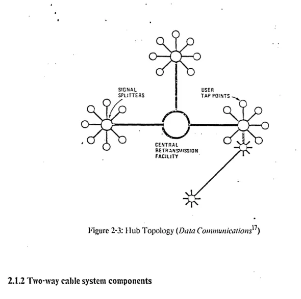
The inferior characteristics of 400 Mhz amplifiers restrict the topology of 400 MHz systems to a hub
design whose branches are shorter than those of tree structures (Figure 2-3). This configuration
resembles a star with the headend at its center, and multiple radially distributed trunks. The maximum distance between the farthest subscriber and the headend is thereby minimized. This reduces the length of the amplifier cascades necessary to cover a given geographical area. Systems can be configurcd with multiple interconnected hubs to cover larger geographical regions. Enhanced transmission methods that are more resisitant to noise and inter-modulation are used to connect the hubs (e.g., digital transmission, frequency modulation, wider guard bands). Widcband, low-attenuation media, such as microwave or fiber optics, are typically used foir the inter-hub links. These
Figure 2-2: Tree Topology (Data Conlunicalions1 6)
methods and media are currently economically prohibitive for use in other segments of the cable plant.
2.1.1.3 Interface equipment
The feeder cable taps off of the distribution cable and carries the signal to the subscriber. The
interface unit, which is also referred to as the customer premises equipment (CPE), connects the feeder
cable to the customer's TV set The interface unit translates the signals taken off of the cable to a frequency band tlat can be received by a standard television. This converter is the simplest form of cable interface unit. In addition, subscribers to pay-television programs, which are sometimes scrambled before transmission, have converters equipped with descramblers1 8.
16Dineson. 1M., Picazzo, J. [22]
18Alternativcely, the pay-television signals are trapped out at the trunk connection to each subscriber's fcceeder cable who does not pay for the premium service.
SIGNAL
SPLITTERS USER
FACILITY
Figure 2-3: 1 ub Topology (Data Conununicationsl7)
2.1.2 Two-way cable system components
2.1.2.1 lIeadend
Two-way communications on a cable system requires that the headend receive upstream signals from the cable distribution plant in addition to transmitting signals downstream. Some of the control structures for data communications require only that the headend translate specified upstream signals onto select downstream channels. Others depend upon the headend for additional addressing and switching capabilities. Some of the upstream signals may be forwarded by the headend to other points on or off of the cable network, while others may be destined for the headend itself. Exactly what equipment. is needed depends on the application. To ensure compatibility with video transmissions, some headends also frame the data signals to look like video.
Most large systems today, both one-way and two-way, employ a minicomputer at the headend for system control, maintenance, and billing. Once the headend is so equipped, numerous network managemnt functions can be implemented at the headend.
1 7
2.1.2.2 Cable distribution plant
Two-way capability implies that the cable distribution plant transmits signals in both directions. The coaxial cable itself has this capability but, the standard one-way cable amplifiers must be modified to accommodate two-way transmission.19 Two-way amplifiers amplify a portion of the cable's firequency spectrum in the upstream direction, and the balance in the downstream direction. The upstream and downstream portions need not be of equal bandwidth, and in most cases are not. The frequency bandwidths allocated for upstream and downstream transmission are completely determined by the amplifiers used. Any one-way system can, in principle, be converted into a two-way system if the amplifiers are replaced with two-way amplifiers.
Two-way cable systems vary in the number of channels allocated to upstream communications. Residential systems typically allocate most of their cable channels to downstream transmission -- 54 Mhz to 300 Mhz for downstream, and 5.75 Mhz to 29.75 Mhz21 for upstream, transmissions on 300 Mhz systems. These are referred to as subsplit systems. Most institutional cable systems, as well as private LACN's, are midsplit systems. These allocate the same number of channels to both upstream and downstream transmission; for example, 5.75 Mhz to 108 Mhz for upstream (reverse), and 162 Mhz to 300 Mhz for downstream, transmission on 300 Mhz systems. These frequency assignments are somewhat arbitrary, using over-the-air T.V. transmission frequency assignments so as to take advantage of widely available (and therefore inexpensive) amplifiers and related equipment. Some cable systems, referred to as dual cable, use two cables. The cables can be operated as two subsplit or inidsplit systems, or one of each. A fourth option uses an entire cable for downstream, and operates the second cable as either midsplit, or subsplit, or entirely upstream2 2.
The data transmission rate achieved on each channel is dctermined by the number of bits per hertz (bits/hz)23 transmitted. This in turn is affected by the noise limitations (see Section 2.3), and the
19The amplifiers on two-way ready systems have slots ready for insertion of upstream amplifier boards. This technique
was prescribed by the FCC in the mid-seventics for all large cable systems. It was an attempt to minimize the cost of future retrofitting, while recognizing that a two-way market did not yet exist. Cf Section 2.1.2.2
See Section 2.3 for other practical limitations to two-way transmission.
2 1
Channels TI - T4 using standard cable nomenclature
2 2
Wang uses a dual cable for its Wangnct and claims to achieve three times the bandwidth at 20% additional cost.
Bits per hertz is the inverse of the efficiency rating, or hz/bit. Bits/hz is felt to be a more useful measure in this instance and will be used throughout the report.
sophistication (and cost) of tie modem. The data rate experienced by each user is also determined by the access scheme used (see Section 2.2), as well as the geographical coverage. E'xisting cable based data communication networks achieve aggregate data rates up to 5 Mbps over each 6 NMhz channel (0.833 bits/hz), depending upon the access scheme and geographical coverage 24. Aggregate data rates
achievable over the full spectrum of a midsplit cable system range upwards of 300 (300 Mbps is an arbitrary example of the data rate achieved assuming 0.5 Mbps per 6 Mhz channel). In comparison, Multipoint I)istribution Systems (MI)S), which use microwave transmission ifcilities, offer at most one or two 6 Mhz channels due to limited over-the-air spectrum availability; and unmodified,
telephone company, local loop facilities (twisted wire pairs) offer up to 4.8 Kbps.
Two-way bridge amplifiers are used to amplify signals onto, and off of, scgments of the cable plant which branch off of the central trunk. In some two-way systems the bridge amplifiers are equipped with added electronics which allow them to be addressed and switched on and off via signals from the headend. In more sophisticated two-way systems, bridges might be equipped to perform diagnostic checks on the network as well.
2.1.2.3 Interface units
Tlhe interface unit for a two-way system must convert signals from the terminal into a form that can
be transmitted over the designated cable channel, and received by the hcadend. The function and complexity of the interface unit depends upon the type of terminal and access scheme used. The interface unit consists of two parts, one is the rf modem, and the other is the control logic (both
digital hardware and software)
Radio frequency nmohdator-demodthltors (if modems) convert digital signals from digital devices into
analog signals which can be carried by the cable network much like video signals. Rf-modem technology has proven very popular for industrial use, and more recently for communications in business environments; however, it remains a relatively costly technology for residential use. Rf-modem costs range upwards of $400. This high cost is partially due to the limited quantities currently manufactured. In addition, the analog complexity of radio frequency components makes Large Scale
2 4Cox Cable's Indax system runs at 28 Kbps over 125 Khz subchannels (.223 bits/hz). Wang's broadband system runs over
shorter distances at speeds up to 12 Mbps over an 18 Mhz channel (0.667 bits/hz). Ungernann-Bass runs at,5 Mbps per 6 Mhz channel (0.833 bits/hz), over distances up to 10 miles.
Integration (I.SI) difficult; therefore, the costs are not expected to decrease as rapidly as many digital comlpotlents.
In a telephone system every customer has its own dedicated wire pair; on a cable television network nodes sharc a coinmmon trunk which passes many households. An access scheme or protocol controls how the cable capacity is shared. Each unit must also be given an unique digital address to identify it for reception of downstream signals. Thus, in addition to the rf-modem a two-way interface unit contains control logic which implements the communication protocol. The interface unit design and cost is largely determined by the access scheme used on the network. Finally, the interface may implement additional capabilities such as anti-jamming techniques, encryption, or other enhanced
features.
2.2 Access schetmes
and
communication protocols for two-way data communications
A number of alternative protocols for data communications over broadband cable have been
implemented. Each of the protocols has a system structure and user environment for which it is most
appropriate. Residential and institutional networks may require different schemes, based on the
differences in their applications. Eventually, agreed-upon standards will be needed to support interconnection of networks with dissimilar higher level protocols.
2.2.1 Description of access schemes
2.2.1.1 Polling
The most common access scheme currently used for two-way communications on cable systems is
polling. The headend continually cycles through the system, addressing a message to each interface
unit to see if it has data to send. It can take as long as 6 seconds to poll every user in a large system, on the order of 100,000 subscribers25 . Unique digital addresses are hard-wired or programmed into each of the subscriber interface units.
2 5
The Minneapolis cable system being built by Rogers Cablesystems Engineering of Canada, specifies a 6 second polling cycle.
The performance of a polling scheme is characterized by the response time realized by the subscriber and the amount of data sent per response. Some polling schemes allow the polled device to reply to the headend only with one of a set of predefined responses; others allow more flexibility in the allowed length of the response. Polling is most often used for pay-per-view billing, as well as for security and energy monitoring applications. Polling methods are appropriate tir transaction services and other data communications services only when traffic is very light, and when response time is not critical.
A modified version of polling uses intelligent bridger-switches. The headend polls one branch of the network at a time by addressing the appropriate intelligent bridge amplifier and allowing all nodes on that branch to simultaneously transmit (using separate, preassigned frequencies) their upstream signals onto the entire upstream portion of the trunk cable. Since only one branch is allowed to transmit at a time, the entire upstream channel spectrum can be used by the nodes on a single branch. lThis method achieves higher data rates than most simple polling schemes but may still suffe•r from long response times due to the polling cycle.
Bintry polling is used to decrease the delay which results from long polling cycles. The headend
sends out polling messages to all points on the network. If the headend receives a response it locates tihe responding device (or one of them) using a binary search technique. The headend turns off half of the network branches and polls the other half. If there is no response, the originally responding device is known to be on the other half of the tree. The network is configured as a long branching tree and this divide-in-half process continues until the headend has isolated one responding node on the network. The customer is serviced and the process begins again. This method is only effective in reducing delay if there are few simultaneous users with messages to send, e.g., security monitoring.
2.2.1.2 FDM
Frequency Division Multiplexing (FDA!) can be used to divide each of the 6 Mhz channels into
smaller subchannels for dedicated use by subscribers2 6. The FDM interface unit is a standard rf-modem tuned to dedicated frequencies, one for transmitting and one for receiving. The receiving
26
Manhattan Cable Television (IMCTV) in New York city uses this approach. MCI'V has operated a data transmission service between uptown and downtown Manhattan since 1975. The service is primarily used by banking and other financial
frequency serves as tie unit's digital address. The data rate is a function of the channel bandwidth and the number of bits per hertz transmitted.
Switched FDM! schemes resemble the current architecture of the telephone system. Each user is
assigned a dedicated subchannel. This frequency assignment serves as the user's address. 'IThe headend reads addressing information on upstream communications and routes the information to the proper downstream subchannel, performing the appropriate frequency translation. '[This access method is appropriate for systems with a limited number of users whose communications are relatively uniform over time. The number of users who can be served by such a scheme is limited to the number of available subchanncls. which in turn is limnited by the minimum acceptable bandwidth of a subchannel. This is far fewer than the number of residential subscribers on even a small two-way system (3,500 or more), but is possibly adequate for an institutional system.
Dynamic assignment FDM makes use of frequency agile modems which allow users to transmit via
one of a set of frequency subchannels; the particular frequency used is determined by the user or by a central controller, i.e., the headend. The central controller dynamically assigns the calling and called nodes a free subchannel for the duration of their communications; polling can be used to identify the node that wishes to set up a connection. While allowing service to many more users, this method is still less suited to bursty traffic types such as computer communications which is characterized by short, high intensity, intermittent communications. Using FI)M alone as the access scheme2 7, when a channel is assigned to a device, even if dynamically assigned, it will lay idle during those times when the device has no data to transmit.
2.2.1.3 TDM
Time division multiplexing (TDAj) allows multiple devices to share a single FDM channel or subchannel by assigning each user a fixed time slot during which it sends its data. A user's address is his time slot. A form of TDM called Time Division Multiple Access (TDAI,) allows many devices along a cable to share a TDM channel; devices insert data into their slot at multiple points along the cable. There are a number of methods for controlling allocation of the time slots using a TDMA scheme. Demand Assigned-Time Division Multiple Access (DA-TDMA) is a more sophisticated TDMA scheme which allows dynamic !location of time slots on a transmission channel. This
2 7
technique was developed for satellite communications, and is generally applicable to high bandwidth
)multipoint communications networks. IA-'TDl)MA uses intelligent microprocessor controlled interface units, as well as a fairly powerful minicomlputer at the headend, to allocate time slots on an as needed basis. A-'l'l)TDMA is appropriate for both high and low speed users, particularly users with high volume requirements.
2.2.1.4 Contention schemes
Contention Schemes are another form of'lTDMA. Aloha [1], Carrier Sense Multiple Access (CSMA), and CSMA with Collision Detect (CSMA-CD) [411 are all candidates for use on residential cable systems. Contention schemes allow all users to share a single channel, or multiple subchannels can be interconnected using a bridging device. For example, using CSMA, when a device has data to send, the interface unit broadcasts packets of information onto the channel. If the unit does not receive an acknowledgment that the packets were received intact (i.e., a collision occurred when two or more units attempted to use the channel simultaneously, resulting in destroyed packets), it retransmits the packets. The more sophisticated schemes allow the devices to detect other traffic on the channel before or during broadcasting, thereby reducing the probability of collision. For example, using
CSM A-CD, if more than one device broadcasts at any one point in time, there is a collision and both
devices backoff and try again after some short but random period of time. Every device scans the
address destination attached to each packet on the channel but reads only the contents of those
packets that are
addressed to it. Contention systems present a tradcoff among data rate, geographical
coverage, and minimum packet size
28. Although LACN contention systems operate at speeds as high
as 5 Mbps per 6 Mhz channel
29, peak data rates for a residential cable are probably limited to 1 or 2
Mbps per 6 Mhz channel (0.1.66 to 0.332 bits/hz), due to wider geographical coverage and lower
guaranteed signal to noise ratios
30Contention schnemes achieve complete connectivity through distributed control. In contrast to
DA-2 8
Estrin, D., Some Technical Considerations in Using a 400-Milz CATV System for Data. Working Paper, Laboratory for Computer Science, M.I.T., May 1981.
2 9
Ungermann-Bass Inc. [63], Net/One Broadband; Wangnet achieves 12 Mbps over 18 Mhz, or 4 Mbps per 6 Mhz.
30
Dickcnson [21] suggests that well-maintained systems should experience signal to noise ratios of 40 dB or greater, which is more than adequate for high performance. But, there are no statistics currently available as to the number. or percentage, of residential cable systems that fit this description. In addition, the residential cable system is exposed to a harsher, and less controllable, environment than a building-wide LACN is. making it difficult to guarantce performance.
TDMA, contention systems require no added complexity at the hcadend beyond signal conditioning; the switching function is inherent to the way in which the channel is shared. This reduced complexity and distributed control is very attractive for the diverse conmmunity of users that is to be served in the residential and small business market. Contention systems are appropriate for multipoint communications between bursty users at medium and high speeds, and short to moderate length messages.
Token passing is a distributed polling method. The I'EEE LACN standards committe3 1 describes tie token access method as follows [32]:
A token controls the right of access to the physical medium; the
node which holds (possesses) the token has momentary control over the medium.
The token is passed by nodes residing on the medium; it is passed from node to node in a logical ring fashion.
Steady state operation consists of a data. transfer phase and a token transfer phase. "The two phases may be combined, in which case the token is transferred in conjunction with a data frame (implicit token).
Monitoring functions within ithe active nodes provide a basis for initialization, recovery, and general housekeeping of tie logical ring. The monitoring functions may be replicated among nodes of the network, but only a few nodes at a time carry the primary recovery responsibility.
As on the contention channel, packet headers are scanned by all interface units on the channel but are selected by only that unit to which they are addressed. In contrast to the contention method described above, this method does not present the speed, distance, packet length trade-off. It
therefore can be used to achieve higher speeds over longer distances. In addition, the performance of a token passing channel does not degrade under heavy loading as severely as does a contention channel. On the other hand, if the channel is lightly loaded, longer delays will be incurred with higher probability; this could be aggravated by extended geographical length of the channel and poses an upper bound to the geographical coverage [54]. A central monitor station is ordinarily used to ensure tie integrity of the token, i.e., that it does not get lost or duplicated. This monitor could be
3 1Institute of 'Ilectrical and Electronics Engineers, Project 802, is attempting to set standards for local area network
located at the headend3 2.
2.2.2 Performance characteristics of access schemes
The choice of access scheme presents a tradcoff among throughput. connectiviii,: availability, and cost.
2.2.2.1 Throughput
The throughput is the data rate experienced by an individual user. It is only a portion of the aggregate data rate offered on the channel. Polling typically offers the lowest thrcughput to the user. Some implementations of bridger-switch polling allow a single branch to make use of the entire upstream channel capacity at a time. Although this increases the peak data rate accommodated, the polling-cycle delays effectively reduce the throughput experienced by the subscriber.
The throughput experienced on a dedicated FI)M channel is equal to the data rate of the modem used. Higher data rates require more dedicated bandwidth, limiting the number of users who can be served in a given frequency allocation. Sending fewer bits per hertz results in cheaper modems but the inefficient use of bandwidth limits the amount of traffic that can be accommodated.
The throughput experienced by a single device on all varieties of TDMA channels is determined by the number of devices served on the channel, i.e., the load factor, since the channel rate is usually equally divided among all nodes. The throughput is also determined by the channel bandwidth allocation, and the specifications of the interface hardware.
2.2.2.2 Connectivity
Connectivity is the ability to communicate with every other point on the network. This requires that
each point have a digital address and that communications can be transported from each point to every other point on the network, i.e. unique addressing and switched services.
Polling is not well suited to multipoint-to-multipoint communications, because the task of collecting and forwarding messages, is cumbersome. Polling is best applied in systems where multiple
32


![Table 3-1 illustrates typical 1981 prices for cable, distribution-plant, hardware components 52 , [37].](https://thumb-eu.123doks.com/thumbv2/123doknet/14537429.534928/58.918.108.792.98.993/table-illustrates-typical-prices-cable-distribution-hardware-components.webp)