Design Sprint for Complex System Architecture Analysis
The MIT Faculty has made this article openly available.
Please share
how this access benefits you. Your story matters.
Citation
Hölttä-Otto, Katja, Valtteri Niutanen, Steven Eppinger, Tyson R.
Browning, H. Mike Stowe, Riku Lampinen, and Andhikaputra
Rahardjo. “Design Sprint for Complex System Architecture
Analysis.” Proceedings of the ASME 2018 International Design
Engineering Technical Conferences and Computers and Information
in Engineering Conference IDETC/CIE 2018, 26-29 August, 2018,
Quebec City, Quebec, Canada, ASME, 2018. © 2018 ASME.
As Published
http://dx.doi.org/10.1115/DETC2018-85774
Publisher
American Society of Mechanical Engineers
Version
Final published version
Citable link
http://hdl.handle.net/1721.1/120352
Terms of Use
Article is made available in accordance with the publisher's
policy and may be subject to US copyright law. Please refer to the
publisher's site for terms of use.
DESIGN SPRINT FOR COMPLEX SYSTEM ARCHITECTURE ANALYSIS
Katja Hölttä-Otto
Design Factory, Department of Mechanical Engineering, Aalto University
Espoo, Finland
Valtteri Niutanen
Department of Mechanical Engineering, Aalto University
Espoo, Finland
Steven Eppinger
Massachusetts Institute of Technology Cambridge, Mass., USA
Tyson R. Browning
Neeley School of Business, TCU Fort Worth, Texas, USA
H. Mike Stowe
theP5DC
Tacoma, Washington, USA
Riku Lampinen KONE Corporation Hyvinkää, Finland Andhikaputra Rahardjo KONE Corporation Hyvinkää, Finland ABSTRACT
A rigorous, in-depth analysis is a common approach in complex system design. Elsewhere, however, more iterative and agile processes and open innovation have become commonplace. We experiment with an agile hackathon-type design sprint for solving industry-provided, complex system engineering problems. In a typical complex system project, significant domain expertise is expected and only one in-depth analysis is typically conducted to make recommendations for a given problem. The question we explore is whether a quick sprint with non-domain experts can result in useful insights for further analysis. We tasked seven teams in parallel to conduct analysis and suggest recommendations for a given company case in only a few hours. The industry challenge was to propose system changes that would mitigate risks due to the long lifecycle of the system and long time from order to delivery. The teams were given two a priori decomposed design structure matrices, representing the product architecture at two levels of granularity, as well as access to several analysis tools. The design sprint resulted in seven sets of recommendations, each with unique insights. The results and their variety highlighted the type of recommendations any given analysis direction would give if pursued further. It provided insights about the many different
ways to potentially address the given challenge. As expected, it also highlighted the difficulty of analysis due to lack of detailed system knowledge. Nevertheless, the sprint was considered successful and meaningful as well as an effective means to augment traditional complex system analysis.
INTRODUCTION
Gaining an outside-in view on a problem is usually beneficial for any company. A fresh set of eyes can result in new ways of thinking and even new innovations. Consequently, various open innovation methods such as hackathons have become common in many industries. Hackathons are typically short-term challenges consisting of a large amount of data that are opened up to a wider audience to be used to discover novel solutions [1]. Hackathons are especially common in data-heavy software projects and digital innovation [1,2] but have become more commonplace in other areas as well. Hackathons can be quick, solutions-oriented events. Another similar trend is the use of agile methodologies that originate from software and digital service development. [3] A core feature of an agile approach is a design sprint [4] – a short-term, targeted design cycle with a clearly defined goal. Hackathons or design sprints, however, are not common in complex system development. Nevertheless,
Proceedings of the ASME 2018 International Design Engineering Technical Conferences and Computers and Information in Engineering Conference IDETC/CIE 2018 August 26-29, 2018, Quebec City, Quebec, Canada
open innovation methodologies have been used in large-scale projects. For example, NASA has run multiple space system hackathons [5].
Similarly, design thinking has become more common in engineering design. For example, Camburn et al [6] recognize how iterative design thinking and systems engineering can and should occur concurrently in an innovation project.
A hackathon, design sprint, or design thinking project typically involves familiarizing oneself with the topic. In complex system projects this can be a challenge. Significant domain and system knowledge is needed to understand a complex system. Thus complex system projects are usually done by expert system engineers. This may be a barrier to the meaningful use of open innovation methods in complex system design. In this paper, we investigate the potential of a hackathon-like design sprint to create system architecture recommendations for a complex system challenge given by a large multinational company.
BACKGROUND
Many prior works have used the design structure matrix (DSM) [7] to represent product system architectures in terms of the constituent components and their relationships. (See [8,9] for recent summaries.) The DSM is a square adjacency matrix showing system elements along its diagonal and other cells showing relationships among them. (In this paper, we use the convention where cell (i,j) in the DSM represents an output from column i to row j.) Methods for managing change propagation [10-12], flexibility [13] and technology integration [14,15] have been developed using DSMs. In addition, product family [16,17] and layout [18] design has been shown to benefit from the use of DSMs. These types of projects typically benefit from DSM clustering algorithms [19-21].
A typical system architecture project involves design of a product family or a single system, where the common system architecture will last from either one variant or product generation to another, or throughout the potentially long lifecycle of a system. However, a typical complex system case only involves one in-depth analysis of the system. In this paper, we investigate what would happen if a hackathon-like design sprint is used to tackle a system architecture challenge instead of one in-depth analysis. Our specific research questions are:
1) Will a DSM-based design sprint bring multiple different analysis results for a complex product architecture challenge?
2) Will the results of a DSM-based design sprint conducted by participants unfamiliar with the system be useful to experts in the case study organization?
In addition, we will report on factors relating to organizing such a design sprint.
APPROACH
We tested the use of a design sprint to analyze a system architecture project as part of the 19th International Design Structure Matrix (DSM) conference held at the Aalto University Design Factory in Espoo, Finland in September 2017. A global
manufacturer of elevators provided the industry case study for the sprint.
In preparation for the industry case study we needed to select the format of the case, and more specifically how to present the system data to the participants. Szajnfarber et al. [5] discuss a tradeoff between system complexity and solvability in a hackathon-like setting. An a priori decomposition will help simplify the problem for the hackathon, but a static decomposed system model also limits the solution space [5]. After considering the two research questions, we choose to do the a
priori decomposition to ensure that we would provide enough
information to non-domain experts participating in the challenge.
Building the DSM
In preparation for the design sprint, a DSM was first built over a period of one month with the case study company. After discussions about various forms of product breakdown structure, a delivery-package-based bill of materials (BOM) was chosen as a starting point. It was a result of a past effort by a company system engineer. This BOM was used to form the rows and columns of the initial DSM.
The DSM consisted of collapsible modules, which enabled building a DSM at two levels of granularity [22]. The matrix was amended and filled iteratively by the first two authors together with the elevator company’s system engineers. The process consisted of 10 face-to-face and online interviews with a few system engineers and at least one expert on each identified subsystem. The interviews lasted approximately 20 hours in total. We followed a similar process in all interviews, starting by explaining the purpose of the interview and then opening discussion with the experts, prompting them to note any direct connections among any of the components in the subsystem. The interviewer would, for example, go through the list of components and ask whether it connected to anything. If a connection was noted, the interviewer would ask to specify the type of connection. We repeated this basic process for each component in each subsystem. After compiling the DSM, we conducted an additional review to ensure that no connections were missed. After some corrections, we sent the DSM back to the system experts to confirm that no critical connections were omitted. All this was to maximize the completeness of the DSM model and help minimize potential subjectivity in the DSM [23]. The resulting component DSM can be considered a high-definition DSM [24]. It consisted of five types of connections: Spatial (s), Material (m), Mechanical Energy (me), Electrical Energy (ee), and Information (i). Two types of energy interfaces were specified to ensure that electrical connections that convey energy were distinguished from signal (information) flows.
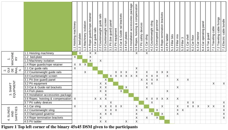
The DSM comprised 10 modules, which further consisted of 45 components. This formed the first level of granularity. When the DSM was further decomposed, 175 components were revealed at the lower level of granularity. The resulting DSMs are partially illustrated in Figures 1-2. For further detail, please refer to Niutanen et al [25].
3 Copyright © 2018 by ASME
The Design Sprint Challenge and data collection
Figure 1 Top left corner of the binary 45x45 DSM given to the participants
Figure 2 Section of the 175x175 DSM given to the participants
1. 1 H o is ti ng m ac hi n er y 1. 2 be d-p lat e 1. 3 M a c h iner y i s o lat ion 1. 4 R o pe g ua rds /r op e r et ai n er 2 .1 C a r g u id e r a ils 2. 2 C o un te rw e igh t g ui d e ra ils 3. 0 C o un te rw e igh t s c ree n 3 .1 P it ( toe gu ard) pa ne l 3 .2 P it eq ui p m e nt 3. 3 C a r & Gui d e rai l br ac k e ts 3. 4 F is h p lat es 3. 5 I ns tal lat io n ac c e s s o ri e s pa c k age 3. 6 R o pe s , h oi s ti ng & c o m pen s a ti o n 3 .7 P it sa fe ty d e vi c e s 4 .1 C a r s lin g 4. 2 C o un te rw e igh t s ling 4. 3 Ov e rs pee d go v e rno r 4. 4 R o pe t er m in at ion br ac k e ts 4. 5 P it l a dd er 5 .1 F ille r b it s 5 .2 F ille r m ix 5 .3 F ille r 3 6. 1 C a r s h el l 6 .2 C ar fl oo r 6 .3 C a r in te ri o r 6. 4 C a r op er a ti n g pa nel 6 .5 T oe gu ard 7 .1 T ra v el in g c a bl e 7 .2 T ra v el in g c a bl e f ix ing s 7. 3 E lec tr ic c abl e b un dl e 1.1 Hoisting machinery X X X X X 1.2 bed-plate X X 1.3 Machinery isolation X X 1.4 Rope guards/rope retainer X X X
2.1 Car guide rails X X
2.2 Counterweight guide rails X X X X X X X X X
3.0 Counterweight screen X X X X X X X X X X
3.1 Pit (toe guard) panel X X X X X X X
3.2 Pit equipment X X X X X X
3.3 Car & Guide rail brackets X X X X X
3.4 Fish plates X X X X
3.5 Installation accessories package X
3.6 Ropes, hoisting & compensation X X X X X X X X X X
3.7 Pit safety devices X X X X X
4.1 Car sling X X X X X X X X X X X X X X X
4.2 Counterweight sling X X X X X X X X X
4.3 Overspeed governor X X X X X X X X
4.4 Rope termination brackets X X X X X
4.5 Pit ladder X X X X 1. M A CHI NE RY 2. GU I DE RA IL S 3 . SH AF T EQ U IPM EN T 4 . S L IN G S A ND SAF ET IES Ca r Sl in g Co m p o n e n t 1 Ca r Sl in g Co m p o n e n t 2 Ca r Sl in g Co m p o n e n t 3 Ca r Sl in g Co m p o n e n t 4 Ca r Sl in g Co m p o n e n t 5 Ca r Sl in g Co m p o n e n t 6 Ca r Sl in g Co m p o n e n t 7 Ca r Sl in g Co m p o n e n t 8 Ca r Sl in g Co m p o n e n t 9 Ca r Sl in g Co m p o n e n t 1 0 Ca r Sl in g Co m p o n e n t 1 1 Ca r Sl in g Co m p o n e n t 1 2 C o un te rw ei gh t S li n g C o m C o un te rw ei gh t S li n g C o m C o un te rw ei gh t S li n g C o m C o un te rw ei gh t S li n g C o m C o un te rw ei gh t S li n g C o m C o un te rw ei gh t S li n g C o m C o un te rw ei gh t S li n g C o m C o un te rw ei gh t S li n g C o m C o un te rw ei gh t S li n g C o m C o un te rw ei gh t S li n g C o m C o un te rw ei gh t S li n g C o m C a r O S G C om pon en t 1 C o un te rw ei gh t O S G c o m C a r O S G C om pon en t 3 C o un te rw ei gh t O S G c om C a r O S G C om pon en t 5 C o un te rw ei gh t O S G c o m O S G c o m po nen t 7 O S G c o m po nen t 8 R o pe t e rm in at ion 1 R o pe t e rm in at ion 2 R o pe t e rm in at ion 3 P it l a dd er F il ler bi ts Fil le r 1 Fil le r 2
Car Sling Component 1 s,me s,me
Car Sling Component 2 s,me s,me
Car Sling Component 3 s s
Car Sling Component 4 s
Car Sling Component 5 s
Car Sling Component 6 s,me s,me
Car Sling Component 7 s,me s s s s,me s s s s,me s
Car Sling Component 8 s,me s s
Car Sling Component 9 s s
Car Sling Component 10 s,me s
Car Sling Component 11 s,me s,me
Car Sling Component 12
Counterweight Sling Component 1 s,me
Counterweight Sling Component 2 s,me s,me s s s s s
Counterweight Sling Component 3 s,me s s,me s,me s s s,me s,me
Counterweight Sling Component 4 s s
Counterweight Sling Component 5 s s s
Counterweight Sling Component 6 s,me s
Counterweight Sling Component 7 s,mes,me
Counterweight Sling Component 8 s,me s s s,me s,me
Counterweight Sling Component 9 s,mes,me
Counterweight Sling Component 10 s
Counterweight Sling Component 11 s s s s
Car OSG Component 1 s,me s s
Counterweight OSG component 2 s,me s s
Car OSG Component 3 Counterweight OSG component 4
Car OSG Component 5 s,me
Counterweight OSG component 6 s,me
OSG component 7 s s OSG component 8 s s 4.1 Car sling 4. SL IN G S A N D SA F E T IES 4.2 Counter-weight sling 4.3 Overspeed governor
The Design Sprint Challenge and Data Collection
The design sprint challenge consisted of a brief description of the company as well as a generic description of the elevator system. Text of the challenge itself is as shown in Table 1. In addition, basic public information on how elevators work was provided. The brief was given on Monday of the conference, giving about two hours of dedicated time during the conference and a free evening for those who wished to work more on the challenge before the presentations of the results on Tuesday morning.
TABLE 1 THE DESIGN SPRINT CHALLENGE
Design Sprint Challenge
An elevator is a complex system that is typically ordered months before it is finally installed on site. The time delay between the contract and specification freeze is significant. In addition, requirements creep or new discovered issues during installation often result in late changes and delays.
The lifecycle of an elevator product is tens of years. Continuous further development and quality improvement during the lifecycle leads to thousands of change requests per year and managing them is a huge challenge during design, manufacturing and installation during the elevator lifecycle.
Also, the supply team would be able to better manage their processes if they had visibility into which modules will need changing and which not. Even the design phase would benefit from reorganizing the structure and their teams to streamline the design process.
Your challenge is to analyze the Elevator DSM (component DSM) given to you and suggest improvements in the architecture or otherwise that could help in predicting and preparing for these issues, even eliminating them. We encourage iteration and experimentation to find the most interesting recommendation. You should prepare a brief 10‐minute presentation of your solution and reasoning behind it to be presented Tuesday morning as well as be prepared to hand over your results in e.g. an Excel file. Data You will have access to a set of DSMs for the same system for your convenience. They are all the same system but at 1 https://ilikeiwish.org/ different level of detail. You may find one more interesting or more convenient for your type of approach. 1) a 175x175 full component DSM with 10 sub‐systems and 45 sub‐subsystems with five types of connections (spatial, material, elec.energy, mech.energy, information). 2) a 175 x175 binary version of the above 3) a 45x45 component DSM with five types of connections (s, m, ee, me, i) at a higher level of hierarchy 4) a 45x45 binary version of the above The current modules have been defined based on logistics and delivery packages. This can be changed.
The participants were provided the elevator DSMs in Excel form. Four versions of the DSM at two levels of granularity [22] were provided, as described in Table 1. In addition, two of the elevator company system experts were available for consultation during the design sprint.
In addition to the challenge itself, eight software tools for complex system DSM analysis were presented briefly (ADePT, BOXARR, iQUAVIS, Lattix, LOOMEO, Problematics, ProjectDSM, Soley). Support for these tools was available during the design sprint for most either in person or via online. The participants were allowed to choose which tools to use, including no tool use at all as well as use of other tools than presented. We can assume this would be similar to a real life case if a company were to run an internal or external design sprint themselves. One might have tools available in the company already or might have hired consultants with specific tools. A system engineer is also likely to use tools and approaches they are already familiar with if it is suitable.
The participants were randomly divided into teams of three. After the initial team set up a few people chose to leave. The final teams were seven teams of 2-3 people (only one team had 2 members). All were subject experts from academia or industry. Their level of expertise varied from a doctoral student to a professor in academia or from a few years to several years of experience in industry. A total of 22 experts participated. Eight were female and 14 male. All teams had at least one male and 4 teams had at least one female member. The participants were from all over the world, but we did not track their nationality or place of current employment.
The teams were asked to give ten-minute presentations at the end as well as submit their slides. Further, the presentations were videotaped. These videos and slides were used to analyze the findings for this paper. In addition, a feedback session was conducted after the presentations. An I like / I wish1 format was used and facilitated by one of the authors. This feedback is also reported in the results section.
RESULTS
We set out to address two research questions:
1) Will a DSM-based design sprint bring multiple different analysis results for a complex product architecture challenge?
2) Will the results of a DSM-based design sprint conducted by participants unfamiliar with the system be useful to experts in the case study organization?
Table 2 shows the summary of the DSM design sprint results. We found that teams used both the 45x45 and the 175x175 DSMs. Teams seemed to prefer the 45x45 DSM for visualization, whereas they seemed to use the 175x175 when they could rely on an algorithm for data analysis or for zooming in on key subsystems or components.
All teams used the binary DSM at least, and some added their own weights to it. They used the interaction type (material, electrical energy, etc.) only as a filtering criterion. For example, team 1 focused only on spatial, mechanical energy, and material flows, assuming that the remaining types are more amenable to wireless connectivity or are otherwise more flexible. Interestingly, team 6 chose to remove spatial connections, assuming those were not as relevant as other connections in terms of the core functionality of the system. We believe this difference is due partially to the backgrounds of the individual participants, to their superficial knowledge of the system, and to the short time allowed for the sprint.
The teams employed a large variety of tools. Some used the DSM tools provided, and some used other tools with which they were already familiar (see Table 2 for details). This was expected as discussed before. Naturally, the type of tool used and assumptions about the quantity and quality of data impacted the possible analyses and results.
It is interesting to note that, while all seven teams had the identical brief, each took a slightly different focus to the analysis. Most used the company system experts to help identify critical components, those likely to evolve, require maintenance, or incur late changes. The most common approach entailed defining modules so that design changes would be contained within a module or so that dynamic components would stay in specific modules rather than be spread out in the system [26]. Depending on the detailed approach and analysis method, the resulting recommendation varied. Two teams identified the Car module as likely to change, albeit one where the changes would probably be well contained. Two other teams also recognized the risk of changes in the Car module, at a component or module level, but did not consider that the changes might already be contained. Teams also commonly identified the Shaft equipment and Electrical systems modules as likely to change, but they also suggested other modules. Thus, based on the design sprint alone, there was no consensus about which modules are critical for change management. The result depends on the type of analysis. See Table 2 for further details.
The teams’ recommendations also differed. Some teams suggested containing changes within carefully planned modules, while others suggested redesigning a key critical component or module. These may be only different ways of looking at the same
problem with the same intention, but the design sprint highlights the diverse ways of looking at and solving a problem.
Team 4 had the most distinct approach, based on their basic understanding of the “late change” impacts on business costs and schedule. Their main recommendation was to change the business model. They would have needed a time-based DSM for a detailed analysis, so they could not do this in the available time. This suggested that their lack of knowledge of the system allowed them to approach the problem from a novel, yet relevant, direction.
It appears that a potential benefit of a design sprint in complex product architecture design is the ability to have multiple preliminary analyses before investing in more detailed analysis. Each team’s approach offered a preview of potential results. A quick trial of many approaches enables selection of the most suitable analysis. This could be relevant also in internal projects and not only in a hackathon-like design sprint.
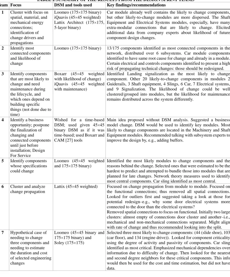
TABLE 2 SUMMARY OF THE RESULTS FROM THE DESIGN SPRINT TEAMS
Team Focus DSM and tools used Key findings/recommendations
1 Cluster with focus on spatial, material, and mechanical energy connections; identification of change drivers and propagations
Loomeo (175×175 binary) iQuavis (45×45 weighted) Lattix Architect (175×175, 5-layer binary)
Car module already well contains the likely to change components, but other likely-to-change modules are more dispersed. The Shaft Equipment and Electrical Systems modules, especially, have many extra-modular connections that are likely to change. Elicited additional data from company experts about likelihood of future component design changes.
2 Identify most
connected components and likelihood of change
Loomeo (175×175 binary) 13/175 components identified as most connected components in the network, distributed over 6 subsystems. Car module components identified to have same root cause for change and already in a module. Certain electrical and controls components identified to present a high risk of propagating technical changes: those should be redesigned.
3 Identify components that are most likely to change and need maintenance during the lifecycle, and which ones depend on building specific things (not done due to time)
Boxarr (45×45 weighted with likelihood of change) iQuavis (45×45 weighted with maintenance)
Identified Landing signalization as the most likely to change component. Other 20 likely-to-change components in modules 2 Guiderails, 3 Shaft equipment, 4 Slings, 6 Car, 7 Electrical systems, and 9 Signalization. The likelihood of change could be well clustered/grouped into modules, but the likelihood for maintenance remains distributed across the system differently.
4 Identify a business opportunity; postpone the finalization of changing and
connected components until just before installation; Design For Service
Wished for a time-based DSM; used given 45×45 binary DSM as if it was time-based; used Boxarr and CAM [27] tools
Main idea proposed without DSM analysis. Suggested a business model change. DSM would be used to identify key modules. Most likely to change components are located in the Machinery and Shaft Equipment modules. Recommended talking with subsystem experts to improve the design by, e.g., adding buffers.
5 Identify components whose specifications could change
Loomeo (45×45 weighted and 175×175 binary)
Identified the most likely modules to change components and the reasons behind the change. Selected ones that were estimated to be the hardest to predict and attempted to bundle those into modules that are planned for late changes. Network theory measures used to identify most central components. Car sling identified as most central.
6 Cluster and analyze change propagation
Lattix (45×45 weighted) Focused on change propagation from module to module. Focused on the functional connections; thus removed all spatial connections. Looked for outliers first and suggested taking a look at those for potential redesign–e.g., why some door electrical systems more connected to the door than the electrical systems?
Removed spatial connections to focus on functional. Initially two large clusters: almost empty of connections door cluster and another–i.e., mechanical and non-mechanical connections separated. Might align with rate of change and thus recommended looking into the split.
7 Hypothetical case of needing to change three components and needing to estimate the duration and cost of selected engineering changes
Loomeo (45×45 binary and 175×175 binary) and Soley (175×175)
Selected three most likely to change components: (44 (slide shoe), 103 (car floor), and 134 (engine drive)). Looked for component criticality using the degree of activity and passivity of components. Car sling identified as most critical. Emphasized mechanical dependencies over information due to difficulty of change. Then looked for the nearest and second degree neighbors for these critical components. This info would then be used for the cost and time estimation, but did not have data.
A Company system engineer was interviewed a little over eight months after the event to inquire about the potential benefits the design sprint may have had to the firm. Three themes emerged from this interview: 1) learning as part of developing the case study, DSM, and the briefing; 2) gaining outside views on their current problem; and 3) material that could be used internally to disseminate DSM-based approaches.
The first benefit already occurred before the actual design sprint. Merely building the DSM required significant effort; a company expert was part of the process the whole time, even though the research team built the DSM itself. The collaboration enabled DSM knowledge transfer to the company. This benefit is directly linked with the choice of building a DSM a prori.
The second benefit is linked to research question 1 and the intended goal of the design sprint. The experts at the company were familiar with the problem and had already worked on similar issues before. The sprint offered novel perspectives on the situation, helping the firm rethink the problem and how to attack it. In fact, follow-on efforts have been initiated at the company.
The third benefit was useful when pitching the further use of DSM-based tools or projects internally. Because the sprint was tailored to the company problem, the potential benefits of various tools and approaches were easy to communicate internally, both in teaching about the approach and especially in communicating with senior management.
In addition to these primary impacts, other benefits mentioned, include building useful new connections with academia and benchmarking with firms in other industries.
However, a design sprint also has many challenges. For example, the strict time limit, while useful for quick results, does not allow for in-depth analysis. This limits analysis quality. Similarly, when the sprint includes outsiders, as in this case, their lack of system knowledge results in recommendations that may not be rational from the system point of view. The restricted time also limited the input data. While the same DSMs were given to all teams, many wished to add additional data, most commonly on the likelihood of change. This consumed much of the limited time. Also, in the spirit of experimentation, most teams tried using a tool with which they were not previously familiar and sometimes struggled with the tool interface and general learning curve. This challenge could be removed from internal design sprints, but it is likely to be present in all open innovation hackathons.
Upon reflection, we question if DSM building could also be part of the sprint, or if better left as a separate effort. This decision likely depends on the context. Here, we chose to build the DSM in advance rather than during the sprint due to the need for many system experts to be consulted in order to create a proper DSM. Szajnfarber et al [5] discussed the importance of a
priori decomposition of system architecture for hackathons.
We can conclude that the design sprint resulted in many useful results. No result is likely usable as is, given that so little time was put toward it, but the sprint allowed for an exploration of multiple approaches to the same problem and thus a broader basis for a decision about how to move forward. The company
feedback was highly positive, and they plan to continue internal investigation of product architecture changes to elevator systems using DSM technology.
LESSONS LEARNED FROM ORGANIZING A DESIGN SPRINT
Overall, the sprint ran smoothly. It engaged the participants and triggered conversations with the company experts. However, it could have been better organized. Table 3 shows the results from the facilitated “I like, I wish” –feedback session at the end of the sprint. All of the teams participated.
TABLE 3 RESULTS FROM THE “I LIKE, I WISH” FEEDBACK SESSION
“I Like…” “I wish…”
Experiencing new tools To do it again The exposure to a new,
real problem I had more time
Working with new people To hear the case before the tool presentations Having tool experts
available
To consider how to divide the teams
Having company experts
available I had better computers Having the detailed DSM I had licenses to the tools
Learning from all seven approaches
To have the company participate in the next annual conference
The diversity of approaches
To consider a seven minute video prior to the conference
The richness of the tools The new ideas, methods, and ways of using the tools
We see from Table 3 that most “Likes” are DSM-tool- or design-sprint-focused in the context of the conference. People enjoyed working with new people, tools, and experts. The two “Likes” bolded in Table 3 refer to the design sprint itself. The participants found that they learned something new from all seven approaches. They saw the other teams’ presentations as an enriching experience that increased their understanding of the elevator system more than their own team’s analysis. This is a valuable insight. The participants had significant system engineering expertise, yet found it valuable to follow how others would have solved the same problem. In addition, the participants appreciated the diversity of approaches. This was the original goal of the sprint as well–to see if a design sprint could generate multiple, different, yet meaningful, insights for a complex system analysis.
Similarly, the “Wishes” are mostly related to the specific organization of this design sprint. Given the unfamiliarity of the participants with the case and the short duration of the sprint, a wish for more time is understandable. However, a sprint is meant
to be quick rather than thorough, and it will remain a tradeoff as to how much time to dedicate to a complex system design sprint. Rather than increasing the time for a single-stage design sprint, it might be more valuable to do a two-stage sprint where each team gets a second round for analysis after seeing other teams’ initial presentations. A common issue was also access to the software tools. Due to licensing issues, the tools could be accessed only on dedicated computers. Few were able to use their own computer for the analysis, and some of the teams had to use relatively dated computers. A free, one-day license would have been preferred. However, having each participant install eight tools on their own computer, prior to the official sprint start, would have also consumed precious time, and fewer than our eight tool vendors might have agreed to this situation. Another discussion centered on whether the tool tutorials should occur before or after the presentation of the design sprint challenge, with some arguing for before, so that it would be possible to evaluate each tool presentation with an actual use case in mind.
The overall feeling was positive, and the plan is to conduct another design sprint at the next DSM conference in 2018.
DISCUSSION AND CONCLUSION
We piloted an open-innovation-inspired design sprint for complex system architecture analysis to investigate its feasibility and usefulness. We concluded that it is a fast way to get many quick views of what might be interesting avenues for further pursuit. The design sprint helped the participants and the company look at multiple DSM and product architecting methods more broadly and critically. It demonstrated the values of a variety of software tools for system architecture analysis. Moreover, it generated several prospects for the company to continue exploring with their internal analysts, perspectives and opportunities which they might not have otherwise noticed. Therefore, we could conclude that a DSM-based design sprint can bring multiple different results for complex systems.
Even for any single analysis, just starting with a premise of many solutions was helpful for thinking critically about the given challenge. Consequently, it might be interesting to experiment with the multiple different approaches, even if one did not have access to multiple separate teams. This more agile approach could work also internally in a company. It might be beneficial to go purposefully in more than one direction on an analysis for a short time before committing to a full analysis. This could help decide which approach is most suitable given the complex, enduring nature of system engineering applications.
Many academic researchers look for ways to apply tools and insights developed in their scholarly work to industrial applications. The DSM-based design sprint proved to be a highly engaging and effective way to introduce new people to the DSM method and to demonstrate how the method can be readily applied to a problem of current interest to industry.
ACKNOWLEDGMENTS
We wish to acknowledge the effort by all that took part in creating the design sprint event and the case study for it as well as all the design sprint participants.
REFERENCES
1. Briscoe, G. (2014). Digital innovation: The hackathon phenomenon. Creativeworks, London.
2. Trainer, E. H., Kalyanasundaram, A., Chaihirunkarn, C., &
Herbsleb, J. D. (2016). How to hackathon: Socio-technical tradeoffs in brief, intensive collocation. In proceedings of the
19th ACM conference on computer-supported cooperative work & social computing pp. 1118-1130. San Francisco, CA,
February 27 - March 02, 2016
3. Highsmith, J., & Cockburn, A. (2001). Agile software
development: The business of innovation. Computer, 34(9), 120-127.
4. Banfield, R., Lombardo, C. T., & Wax, T. (2015). Design
Sprint: A Practical Guidebook for Building Great Digital Products. " O'Reilly Media, Inc.".
5. Szajnfarber, Z., Vrolijk, A., & Crusan, J. (2014). Exploring
the interaction between open innovation methods and system
complexity. 4th international engineering systems
symposium, Hoboken, New Jersey.
6. Camburn, B. A., Auernhammer, J. M., Sng, K. H. E.,
Mignone, P. J., Arlitt, R. M., Perez, K. B., ... & Wood, K. L. (2017). Design Innovation: A Study of Integrated Practice.
ASME International Design Engineering Technical Conferences and Computers and Information in Engineering Conference. Cleveland, Ohio, August 6-9, 2017
7. Steward, D V. (1981). “The Design Structure System: A Method for Managing the Design of Complex Systems.”
Engineering Management, IEEE Transactions On, no. 3: 71–
74.
8. Eppinger, S D. and Browning, T. R. (2012). Design structure
matrix methods and applications. MIT press.
9. Browning, T. R. (2016). Design structure matrix extensions and innovations: a survey and new opportunities. IEEE
Transactions on Engineering Management, 63(1), 27-52.
10. Giffin, M., de Weck, O., Bounova, G., Keller, R., Eckert, C.,
& Clarkson, P. J. (2009). Change propagation analysis in
complex technical systems. Journal of Mechanical
Design, 131(8), 081001.
11. Clarkson, P. J., Simons, C., & Eckert, C. (2004). Predicting
change propagation in complex design. Journal of
Mechanical Design, 126(5), 788-797.
12. Hein, P. H., Menon, V., & Morkos, B. (2015). Exploring
requirement change propagation through the physical and functional domain. ASME International Design Engineering
Technical Conferences and Computers and Information in Engineering Conference.August 2-5 2015, Boston, MA
13. Rajan, P. P., Van Wie, M., Campbell, M. I., Wood, K. L., &
Otto, K. N. (2005). An empirical foundation for product flexibility. Design Studies, 26(4), 405-438.
14. Suh, E. S., Furst, M. R., Mihalyov, K. J., & de Weck, O. L.
(2008). Technology infusion: An assessment framework and case study. In ASME International Design Engineering
Technical Conferences and Computers and Information in Engineering Conference. Brooklyn, New York, August 3–6,
2008
15. Garg, T., Eppinger, S., Joglekar, N. & Olechowski, A. (2017) Using Technology Readiness Levels and System Architecture to Estimate Integration Risk. International Conference on
Engineering Design, Vancouver, August 2017, pp. 301-310.
16. Jung, S., & Simpson, T. W. (2016). An integrated approach
to product family redesign using commonality and variety metrics. Research in Engineering Design, 27(4), 391-412.
17. Otto, K., Hölttä-Otto, K., & Simpson, T. W. (2013). Linking
10 years of modular design research: alternative methods and tool chain sequences to support product platform design. In ASME International Design Engineering Technical
Conferences and Computers and Information in Engineering Conference. Portland, OR. August 4-7, 2013.
18. Niutanen, V., & Otto, K. (2017). Field Isolation as a Basis for
Modular Product Architecture. In ASME International
Design Engineering Technical Conferences and Computers and Information in Engineering Conference. Cleveland,
Ohio, August 6-9, 2017
19. Wilschut, T., Etman, L. F. P., Rooda, J. E., & Adan, I. J. B. F.
(2017). Multilevel Flow-Based Markov Clustering for
Design Structure Matrices. Journal of Mechanical
Design, 139(12), 121402.
20. Borjesson, F., & Hölttä-Otto, K. (2012). Improved clustering
algorithm for design structure matrix. ASME International
Design Engineering Technical Conferences and Computers and Information in Engineering Conference. Chicago, Illinois, August 12–15, 2012
21. Sanaei, R., Otto, K., Wood, K., & Hölttä-Otto, K. (2017). A
rapid algorithm for multi-objective Pareto optimization of modular architecture. DS 87-4 Proceedings of the 21st
International Conference on Engineering Design (ICED 17) Vol 4: Design Methods and Tools. Vancouver, Canada,
August 21-25, 2017.
22. Chiriac, N, Hölttä-Otto, K., Lysy, D., & E. S. Suh. 2011 "Level of modularity and different levels of system granularity." Journal of Mechanical Design 133.10: 101007.
23. Maurer, M., Pulm, U., Ballestrem, F., Clarkson, J., &
Lindemann, U. (2006). The subjective aspects of design structure matrices: Analysis of comprehension and application and means to overcome differences. In ASME 8th
Biennial Conference on Engineering Systems Design
24. Tilstra, A. H., Seepersad, C. C., & Wood, K. L. (2009).
Analysis of product flexibility for future evolution based on design guidelines and a high-definition design structure matrix. ASME International Design Engineering Technical
Conferences. San Diego, CA. August 30–September 2, 2009. 25. Niutanen, V., Hölttä-Otto, K., Rahardjo, A., Stowe, H., Helo,
P., and Pulkkinen, A., 2017, Complex Elevator System DSM - Case for a DSM Design Sprint. Proceedings of the 19th International Design Structure Matrix Conference.
11-13.9.2017 Espoo, Finland. ISBN 978-3-00-057479-5 26. Engel, Avner, Tyson R. Browning, and Yoram Reich (2017)
“Designing Products for Adaptability: Insights from Four Industrial Cases,” Decision Sciences, 48(5): 875-917. 27. CAM tool: Cambridge Advanced Modeller (CAM): 2010:
Wynn, D.C., Wyatt, D.F., Nair, S.M.T. and Clarkson, P.J. "An
Introduction to the Cambridge Advanced Modeller",
Proceedings of MMEP 2010, Cambridge, UK, 2010. Tool