From Oil Field to Ptychography: Applications of FIB SEM in NanoGeoScience
K.N. Dalby1, H.O. Serensen1, D. Mueter, D.Jha1, J. C. da Silva2, and S. L.S. Stipp1
1. NanoGeoScience Group, Department of Chemistry, University of Copenhagen, Denmark 2. Paul Scherrer Institut, 5232 Villigen PSI, Switzerland
Hydrocarbons fuel our current global economy and will likely also do so in the foreseeable future, until greener fuels partly will replace hydrocarbons. Future production of hydrocarbons relies on finding new oil accumulations and/or improving the recovery of known hydrocarbon accumulations where the current technology leaves 50-75% of the hydrocarbons in the subsurface due to inefficiency of the microscopic recovery methods and poor areal sweep [1]. A better understanding of the oil-water-mineral interaction may provide new recovery methods that leave less oil in the North Sea chalk/sandstone reservoirs. As the rocks that host the oil reservoirs in the North Sea basin are the same as the rocks that host our groundwater reserves a better understanding of the oil-water-mineral interaction may also help us remediating soils contaminated by oil, pesticides, solvents and other organic contaminants or cleaning our water reservoirs.
Physical mechanisms proposed for inhibiting oil release include the wettability and connectivity of the pores in the rock and the presence of clays [2], whose dimensions range from micrometer to nanometer. Advances in focused ion beam scanning electron microscopy (FIB SEM) have provided new opportunities to examine the physical (and chemical) properties of rocks at the microscale [3], as well as to prepare samples for nanoscale probing using advanced 3D X-ray imaging techniques [4]. Hard X-ray Ptychographic tomography is a new imaging technique that has been applied in materials science [5] where it simultaneously provides quantitative absorption and phase-contrast tomograms with high sensitivity. The spatial resolution in the images is very high and it is mostly limited by the scattering length and thickness of the specimen [6], where the smaller the sample, the higher the resolution. Recently 16 nm isotropic 3D resolution was demonstrated [6]. So, the preparation of samples from composite material sufficiently thin for ptychographic-tomgraphy experiment can be challenging. Rocks, for example, occupy the end of the spectrum of difficult composite materials because of their broad range of hardness. Our task was to develop a method for producing samples from chalk, a rock composed of countless submicrometer crystals of biogenic calcite. Since the chalk is both hard and friable, it is very difficult to work with. Our goal was then to find new conditions to reduce the sample preparation time and to improve the final sample quality. Here we present a method for producing ptychography samples for hard and brittle materials using FIB SEM.
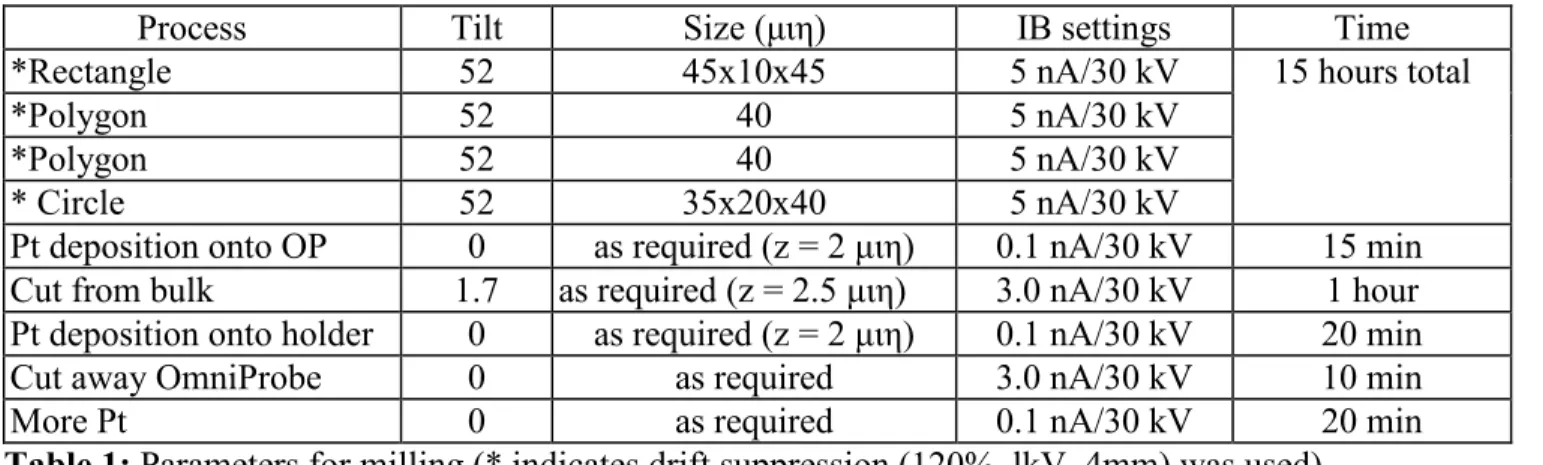
Chalks, and many composite materials, are insulating but it is an advantage to avoid coating them with a conductive film (of gold or carbon). Instead, to reduce charging caused by the focused ion beam, the electron beam (EB) was used for charge compensation. The parameters for this drift suppression (DS), as well as milling conditions, are presented in Table 1. We started with finding a suitable edge of the sample. We milled a rectangle and two polygons close to the edge and then a cylinder. The first cylinder was thinned, using a pattern with a smaller inner diameter (close to the final diameter required). We aimed at making several samples with a final diameter between 8 and 30 micrometers. The milled cylinders were welded to the OmniProbe micromanipulator using platinum and cut away from the bulk material. The cylinders were then mounted and welded onto sample holders (see Figure 1a) that were compatible with the ptychographic tomography set up [6,7] and the OmniProbe was cut free. More
316
doi:10.1017/S1431927614003304 © Microscopy Society of America 2014Microsc. Microanal. 20 (Suppl 3), 2014
https:/www.cambridge.org/core/terms. https://doi.org/10.1017/S1431927614003304
platinum was added to the base of the sample to ensure that it stayed in place during transport and analysis. Successful samples were imaged (Figure 1b) at the cSAXS beamline at the SLS (Swiss Light Source), Paul Scherrer Institut, Switzerland [8].
References
[1] P.L. McGuire, et al. SPE (2005), p. 93903.
[2] A. Lager, K.J. Webb and C.J. Black, SCA conference proceedings (2006). [3] R. Wirth, Chemical Geology 261 (2008), p. 217.
[4] J.J. Lombardo et al., Journal of Synchrotron Radiation 19 (2012), p. 789. [5] M. Dierolf et al, Nature 467(2010), p.436.
[6] M. Holler et al., Scientific Reports 4 (2014), p. 3857
[7] M. Holler et al., Review of Scientific Instruments 83 (2012), p. 073703.
[8] The authors acknowledge funding from P3 Project, funded by Maersk Oil and Gas A/S and the
Danish National Advanced Technology Foundation, and by the Danish Council for Independent Research (via DANSCATT).
Process Tilt Size (μιη) IB settings Time
*Rectangle 52 45x10x45 5 nA/30 kV 15 hours total
*Polygon 52 40 5 nA/30 kV
*Polygon 52 40 5 nA/30 kV
* Circle 52 35x20x40 5 nA/30 kV
Pt deposition onto OP 0 as required (z = 2 μιη) 0.1 nA/30 kV 15 min
Cut from bulk 1.7 as required (z = 2.5 μιη) 3.0 nA/30 kV 1 hour
Pt deposition onto holder 0 as required (z = 2 μιη) 0.1 nA/30 kV 20 min
Cut away OmniProbe 0 as required 3.0 nA/30 kV 10 min
More Pt 0 as required 0.1 nA/30 kV 20 min
Table 1: Parameters for milling (* indicates drift suppression (120%, lkV, 4mm) was used).
Figure 1. (A) A scanning electron microscope and (B) rendering of the tomogram obtained by
ptychographic tomography for the chalk sample. The brighter color displays the pore throat within the micro structure of the chalk (darker).
317 Microsc. Microanal. 20 (Suppl 3), 2014
https:/www.cambridge.org/core/terms. https://doi.org/10.1017/S1431927614003304