555
European Journal of Trauma 2006 · No. 6 © Urban & Vogel
1 Division of Trauma Surgery, Department of Surgery, University
Hospital of Zurich, Switzerland,
2 Interventional Radiology, Department of Radiology, University
Hospital Basel, Switzerland,
3 Trauma Unit, Department of Surgery, University Hospital of Basel,
Switzerland,
4 CARCAS Switzerland, collaborative project of the University
Hospitals of Basel and Zurich, Switzerland.
Received: December 02, 2005; revision accepted: March 16, 2006.
Image Fusion for Intraoperative Control
of Axis in Long Bone Fracture Treatment
Peter Messmer
1,4, Felix Matthews
1,4, Christoph Wullschleger
3,4, Rolf Hügli
2,4,
Pietro Regazzoni
3,4, Augustinus L. Jacob
2,4Abstract
Background: The incidence of malalignment after long bone fracture fixation is reported to be between 0 and 37%. Modern fracture treatment strives towards closed reduction and minimally invasive fracture fixation, thus not exposing the fracture itself. Hence, the occurrence of malalignment might even be higher than previously reported and quite frequently even necessitate sec-ondary operations. Minimally invasive techniques rely heavily on intraoperative fluoroscopy. However, fluoro-scopic images have small cross-sections and conse-quently limit intraoperative visualization of the limb to individual segments only. Under these circumstances, correct alignment of fragments in long bone fractures is often compromised.
Methods: We present a new software prototype using an absolute reference panel to concatenate two or more discontinuous fluoroscopic images into one single panoramic picture. The reference panel is placed on the operating table under the limb to be examined. Prior to digital picture fusion, the software applies non-linear distortion, picture scaling and de-rotation algorithms to the fluoroscopic images.
Results: The presented software runs on a notebook and processes images generated by a commercially available mobile C-arm within seconds. The
reliability of alignment in the panorama picture is found to be numerically adequate and the technique appropriate for clinical use.
Conclusions: This method aims to improve the intraoperative visualization in minimally invasive osteosynthesis and therefore diminish malalignments in long bone fracture treatment.
Key Words
Computer assisted orthopedic surgery · Fluoroscopy · Image fusion · New technology
Eur J Trau ma 2006;32:555–61
DOI 10.1007/s00068-006-5159-5
Introduction
Axial malalignment is a common problem in long bone fracture fixation. Malalignment after long bone fracture fixation is reported to be 0–37% [1–8]. The problem may even be more accentuated, due to the tendency towards minimally invasive surgery, in which the fracture itself is not exposed as in direct anatomical reduction. Particu-larly in the cases with comminuted fractures, it is dif-ficult to achieve correct axis, rotation and length even with open surgery.
Regrettably, these deformities are often only detec-ted postoperatively when correct antero-posterior and lateral X-rays of the entire limbs are taken. During the operation, the surgeon has access only to individual fluoroscopic images with small cross-section, which do not show the entire length of the bone or the limb.
5159.indd 555
556
European Journal of Trauma 2006 · No. 6 © Urban & VogelMoving the active fluoroscope, from one end of the bone to another, only produces a vague impression of the entire bone or leg. Moreover, this picture is lost immediately after the imaging process is finished, and requires higher radiation exposure.
Krettek et al. [9] described a number of intraopera-tive clinical examinations, together with image intensi-fication, to achieve limb alignment in Injury 1998. These techniques are helpful but often imprecise and may require comparative examination of the contralateral limb. This is difficult when the patients lies on a frac-ture table and it is even impossible when the contrala-teral leg has been draped or positioned in a leg support device. The so-called “cable technique” is a popular clinical method, for intraoperative analysis of varus– valgus deformity in the coronal plane. A wire is span-ned from the anterior superior iliac spine to the first interdigital space, to assess limb axis. However, hip abduction and adduction will affect the measure-ment and the method may be imprecise. The preci-sion of the “cable method” can be improved by using an image intensifier in the anterior–posterior position for visualization of bone landmarks. The patient lies in supine position with the knee extended and the patella positioned anteriorly. With help of the image intensifier, the position of the cable – relative to the center of the femoral head, the knee joint and the tibial plafond – far better indicates the axial deviation in the frontal plane. Again there are many sources of error and it seems to be unjustified to rely only on these simple methods for intraoperative varus–valgus analysis.
Outside the operation room, a number of modern radiographic techniques exist to determine limb axis, alignment and rotation. These are conventional antero-posterior and lateral long-plate radiographs as well as CT or MRI scans of the limbs [10, 11]. Malrotation is best demonstrated in a CT scan of both limbs, by analyzing superposed CT slices (e.g., femoral condyles and femur neck for antetorsion). Angulation in the coronal plane (i.e., varus–valgus deformity) is best analyzed on a CT scout or on anterior–posterior long plate radiographs of the entire limb. The lateral long plate radiographs help to determine sagittal plane angulation (i.e., antecurva-tum or recurvaantecurva-tum). Unfortunately, these techniques are normally not available during the operation.
Fluoroscopy is generally available in the operation room. However, it has several limitations in determining axis, rotation and length. The size of the fluoroscopic image is determined by the technical data of the C-arm
and the distance of the object to the C-arm, which allows an image cross-section of 12–15 cm. Therefore, at least five to six fluoroscopic images are necessary to see the entire limb in one plane. The surgeon must look at these images sequentially and mentally reconstruct them into an integrated picture. During the operation, it is very difficult to detect even relevant deformities (> 5°) with this method, which would enable the surgeon to per-form necessary correction immediately during the same anesthesia.
Saleh et al. [12] described, already in the early 1990s, an alignment grid to get accurate bone axis in fracture reduction and corrections of malunions. They write about further development with a ruler to determine the length of the limb, but neither show any examples nor give further details. Yaniv & Joskowicz [13] has adopted the idea of a ruler and present a method composing indi-vidual overlapping images into an undistorted panora-mic view. Their method relies on four assumptions: (1) images are acquired in a fronto-parallel setup; (2) the C-arm orientation does not change during the calibra-tion and the image acquisicalibra-tion; (3) there is a sufficient overlap between the individual fluoroscopic X-ray images; and (4) the user selects the reconstruction plane. Particularly, the necessary overlap means a high number of images with a consequent increase of radiation. More-over, it may be difficult to keep the C-arm orientation unchanged during the movement along the limb.
The limitations of the current fluoroscopic image intensifiers, and the methods described above, motiva-ted our search for an improved computer-based solution to integrate several fluoroscopic images into a larger picture. Our aim was to design a robust and fast method for image fusion that can be applied on images genera-ted by any fluoroscopic image intensifier, without the need of overlap and constant C-arm orientation.
This work presents the prototype of a new method to acquire individual fluoroscopic images and process them to produce a larger composite panoramic pic-ture of the limb, even without taking images of the full scene. The method acquires fluoroscopic images, generated by a commercially available mobile C-arm, in conjunction with a translucent reference panel and a laptop computer.
Materials and Methods
We opted for a method employing a reference panel with absolute references. For this purpose, we designed and constructed an X-ray translucent panel containing a
5159.indd 556
557
European Journal of Trauma 2006 · No. 6 © Urban & Vogel grid of radio-opaque absolute position markers. This panel is placed horizon-tally on the operation table underne-ath the limb to be examined. During antero-posterior imaging, the X-rays beam is perpendicular to the panel and projects the reference grid onto the fluoroscopy images. These images are then exported in DICOM format (640 × 512 pixels, 8 bit gray scale) to our panorama imaging software.
Several processing steps are neces-sary to concatenate the individual pic-tures into a larger panorama image: (a) the non-linear distortion of the fluoroscopic image must be digitally
corrected, (b) the individual pictures must be scaled to a comparable size to achieve an isometric mapping, (c) pictures must be de-rotated in respect to each other to attain the same orientation within the visualization plane, (d) the individual pictures must be mapped into corrected translational relationship to each other. The following paragraphs describe the method in more detail.
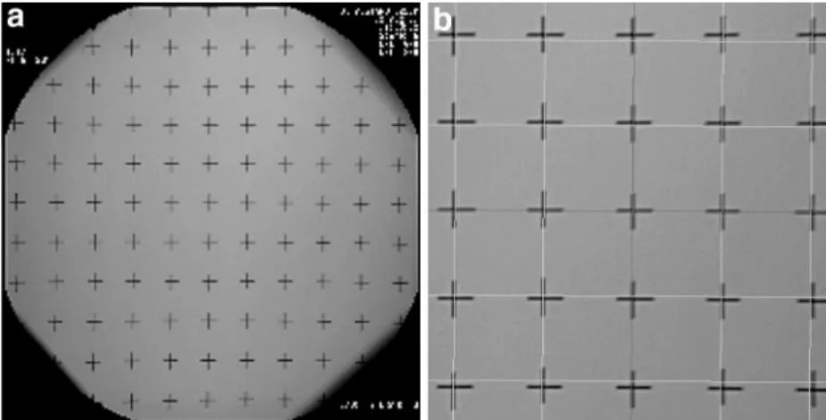
Distortion Correction
Due to the physical characteristics of the image intensifier’s X-ray beam, a cylindrical structure appears distorted on the fluoroscope picture. Two equidistant points appear closer in the center of the picture and more distant and darker toward the image edges. To correct this non-linear distortion effect, pincushion equalization must be performed prior to picture acqui-sition. During a once only calibration step, a circular panel with a grid of beads is placed in the optical path of the C-arm (the so-called pincushion). A translation vector for each bead is computed based on the known true bead distance. This vector array is subsequently applied to each acquired fluoroscopy image, using bili-near interpolation. Further, the pixel intensities are cor-rected using 4 × 4 pixel mask cubic–spline interpolation. The pincushion calibration panel is only required for a one-time calibration. Figure 1a shows the pincushion layout and depicts a distorted, native fluoroscopy image. Figure 1b shows the digitally corrected picture. Note: Newer generation fluoroscopes (e.g., the Siemens ISO-C 3D or the Philips Libra) already have distortion cor-rection algorithms integrated and thus do not require this first pre-processing step.
Absolute Referencing
Our absolute reference panel contains an orthogonal raster of markers. Each node contains a little pictogram consisting of a cross-hair surrounded by four equal quadrants. Each quadrant contains an individual tag in binary format (Figure 2). The upper left and right quadrants describe the row and column, respectively. The lower right tag contains an absolute panel number. The lower left tag contains markings, characterized by the missing intermediate bit. These are used to deter-mine the orientation of the pictogram.
The panorama software recognizes these picto-grams on the fluoroscopy picture and can decipher the
Figures 1a and 1b. Fluoroscopy images require non-linear distortion correction. a) Non-linear
distortion causes equidistant nodes to appear more distant towards the periphery. b) After distortion correction, the crosshairs of the pincushion are orthogonal again.
Figure 2. Reference panel with binary coded absolute references. Each
crosshair is a = 15 mm wide, b = 30 mm apart and has digital markings that are c = 5 mm or d = 3 mm long and e = 3 mm apart. The top left quadrant codes the column, the top right the row and the bottom right is a panel constant. The bottom left quadrant with the “missing” bit is used to determine the orientation.
5159.indd 557
558
European Journal of Trauma 2006 · No. 6 © Urban & Vogelbinary coded node position. The panorama program contains a virtual grid representing all nodes of the panel. Subsequently, the program computes the trans-lation of each node, detected on the fluoroscopy image, to the corresponding node on the virtual grid. The obtained translation vector function is then applied to all pixels of the fluoroscopy image. Thus, the entire picture is scaled, de-rotated and mapped to its correct position on the virtual grid in one single processing step. The procedure is repeated with each acquired fluoroscopy image, thereby progressively completing the panoramic picture.
Hardware and Software
The absolute reference panel was created using a Ple-xiglas compound. The markers were etched, similar to the process of creating printed circuit boards. The reference panel measures 1,300 × 350 × 5 mm, weighs 1.6 kg and contains 360 nodes arranged in 9 columns and 40 rows.
All written software routines are object-oriented classes in C++. For visualization, a license-free acade-mic version of QT was deployed. OpenGL was used for low-level image processing and graphic card accessing. All libraries employed (C++, OpenGL, QT) are availa-ble platform independent (e.g., Linux, Unix, Windows). For ease and performance, we employed a Linux opera-ting system for development.
Evaluation
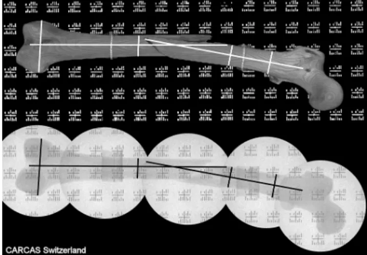
We validated the panorama procedure using three distinct plastic bones (Synbone AG, Malans/Switzer-land): (1) a femur with mid-shaft fracture, (2) a defor-med femur and (3) a pelvis. The bones were mounted on cardboard supports 7 cm over the reference panel, to emulate effective bone–panel distance due to inter-posed soft tissue in a patient. Initially, the entire test rig (Figure 3) was scanned using a Siemens Somatom CT (120 kV, 0.75 mm slice thickness) and a scout pic-ture generated. Subsequently, the identical test rig was
examined by fluoroscopy with a Siemens Siremobile ISO-C 3D mobile C-arm.
To demonstrate correct alignment, the crosshair coordinates (nodes) on the panorama image were manually digitized. The preliminary scaling factor was determined from a node-pair located on only one fluo-roscopy image and compared to a node-pair located on other fluoroscopic images. Once uniform scaling was ascertained, the distance between two nodes located on separate fluoroscopy images were calculated and compared to the true distance known from the panel specifications. Further, several nodes located in one row or column were digitized and linear regression analysis performed on those nodes to determine slope and R-squared (ideally 0). Supplementary to numeric evaluation, the obtained mosaic pictures were shown to clinical experts along with the corresponding CT scout images. The experts were asked to qualify usa-bility and accuracy of the panorama from a clinical perspective.
Results
We developed a panorama mosaic software prototype that runs on a commercially available laptop having a Pentium IV processor. The entire scaling, de-rota-tion and alignment procedure required less than 1 s per frame on the described hardware and synthesized exceptionally illustrative panoramic images (Figure 4).
The procedure was tested on fluoroscopy images in which the panel markers had been partially obstructed. The method was stable with only two visible nodes per fluoroscopy image.
Figure 3. Test rig setup: a Synbone plastic femur is mounted on the
reference panel for CT scanning and fluoroscopy imaging.
Figure 4. Comparison of Scout picture of the plastic bone obtained
from CT scan and panorama mosaic concatenated from individual fluoroscopy images.
5159.indd 558
559
European Journal of Trauma 2006 · No. 6 © Urban & Vogel
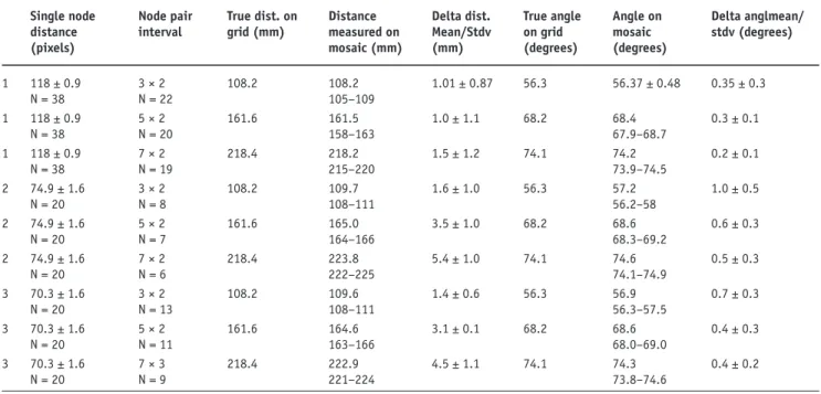
The scaling of individual fluoroscopy images was highly consistent throughout the composite image. This is substantiated by the low variability of the distances between two diagonally adjacent nodes located on the same fluoroscopy image.
Node distances and trigonometrically determined angles, between the nodes in respect to the panel’s ori-entation, proved high precision of the concatenated panorama image. The angular deviation, between nodes located over 200 mm apart on individual fluoroscopy images, never exceeded 1°.
Table 1 shows an extract of the scaling evaluation and the distance and angle computations, as compared to the known dimensions of the panel’s grid.
Precision of node positions was further established using linear regression analysis. Series of nodes in the same columns had R-squared values between 0.71 and 0.77.
The experts judged the panoramic images, matched to the CT scout of the pertinent test rig, to be all of out-standing quality and precision (Figure 4).
Discussion and Conclusion
The incidence of angular malalignments, after closed reduction and internal fixation of tibial and femoral fractures, is up to 37% in the sagittal and coronal plane [1–8]. Despite intraoperative fluoroscopy, the
detection and correction of malalignment is difficult, due to limited viewing capabilities of the small cross-section of the C-arm images. Unfortunately, malalign-ment and leg length differences are therefore often only detected during postoperative clinical examination and on postoperative long-plate X-ray investigations. However, to avoid re-operation and to lower costs, correction of malalignment is best performed during the initial operation itself, for which better intraopera-tive visualization is a prerequisite. In the following, we outline some technical methods to assist the surgeon in evaluating alignment.
Angiography Panorama
Angiography devices deployed in interventional radio-logy already have panoramic imaging functionality. Because such angiography devices are mounted on rails, the absolute position of the C-Arm is known at the time of picture acquisition. Further, the C-Arm does not rotate around the axes of the X-ray beam, i.e., pictures do not require de-rotation. Concatenating angiography images is therefore trivial and even slight axial malalign-ments are clinically irrelevant. In contrast, the mobile C-arms used for intraoperative fluoroscopy have no indication of absolute or relative position with respect to the object being examined. Moreover, already minor malalignments on one fluoro-view (e.g., 5° valgus in the
Table 1. Precision analysis of panorama image. The distance between two nodes on the same panel determines the scaling factor (pixels/mm).
The distance and angle between distinct node pairs located on separate fluoroscopy images demonstrates precise alignment.
Single node distance (pixels) Node pair interval True dist. on grid (mm) Distance measured on mosaic (mm) Delta dist. Mean/Stdv (mm) True angle on grid (degrees) Angle on mosaic (degrees) Delta anglmean/ stdv (degrees) 1 1 1 2 2 2 3 3 3 118 ± 0.9 N = 38 118 ± 0.9 N = 38 118 ± 0.9 N = 38 74.9 ± 1.6 N = 20 74.9 ± 1.6 N = 20 74.9 ± 1.6 N = 20 70.3 ± 1.6 N = 20 70.3 ± 1.6 N = 20 70.3 ± 1.6 N = 20 3 × 2 N = 22 5 × 2 N = 20 7 × 2 N = 19 3 × 2 N = 8 5 × 2 N = 7 7 × 2 N = 6 3 × 2 N = 13 5 × 2 N = 11 7 × 3 N = 9 108.2 161.6 218.4 108.2 161.6 218.4 108.2 161.6 218.4 108.2 105–109 161.5 158–163 218.2 215–220 109.7 108–111 165.0 164–166 223.8 222–225 109.6 108–111 164.6 163–166 222.9 221–224 1.01 ± 0.87 1.0 ± 1.1 1.5 ± 1.2 1.6 ± 1.0 3.5 ± 1.0 5.4 ± 1.0 1.4 ± 0.6 3.1 ± 0.1 4.5 ± 1.1 56.3 68.2 74.1 56.3 68.2 74.1 56.3 68.2 74.1 56.37 ± 0.48 68.4 67.9–68.7 74.2 73.9–74.5 57.2 56.2–58 68.6 68.3–69.2 74.6 74.1–74.9 56.9 56.3–57.5 68.6 68.0–69.0 74.3 73.8–74.6 0.35 ± 0.3 0.3 ± 0.1 0.2 ± 0.1 1.0 ± 0.5 0.6 ± 0.3 0.5 ± 0.3 0.7 ± 0.3 0.4 ± 0.3 0.4 ± 0.2 5159.indd 559 5159.indd 559 12/13/2006 8:02:38 PM12/13/2006 8:02:38 PM
560
European Journal of Trauma 2006 · No. 6 © Urban & Vogelfemur shaft) can result in substantial deformities when extrapolated to the length of the entire limb (e.g., up to 10 cm inter-malleolar distance).
Navigation and Referencing
Recently, methods have been developed that allow intraoperative navigation for arthroplasty and long bone surgery. They employ dynamic 3D referencing using infrared cameras. Suhm et al. [14] described a scenario, where the navigation system tracks the C-arm and helps positioning the device. One could also imagine using the position information of the C-arm obtained from the navigation system to assemble individual fluoro-images to a panorama picture. Navigation systems are however very costly, require extensive instruction of the operator or even the presence of a dedicated technician during the operation. They are not readily available and mostly too complex to deploy in the emergency situation, while treating trauma patients.
Overlapping Panorama
Yaniv & Joskowicz [13] described a method for con-catenating fluoroscopic images that uses a sterile metal-lic ruler placed as reference alongside the limb. This method requires adjacent, overlapping pictures to be taken. The procedure then matches corresponding regi-ons of the overlaps and creates a panorama. The disad-vantage of Yaniv’s method is that to evaluate the axis of the bone, fluoroscopy pictures of the entire limb must be taken, thus increasing radiation exposure.
Absolute Referencing
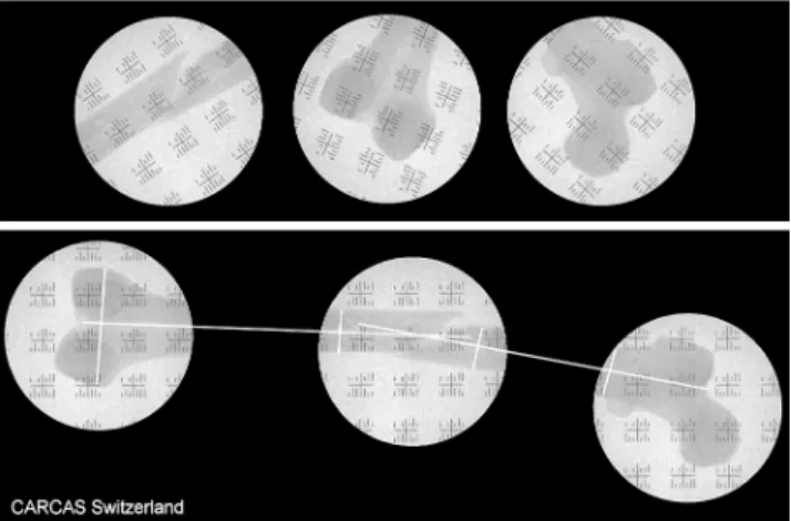
In this report, we present a prototype for computer-aided image fusion, which relies on a reference panel with absolute coordinates. Our method matches the indivi-dual fluoroscopy pictures to a preset raster and does not depend on image overlapping. Thus, two images located well apart one from another (e.g., both metaphysis of a long bone) can still be displayed in precise relation to one another. This is a major advantage of absolute referencing, as it is no more necessary to acquire fluo-roscopy images along the entire length of the limb. For example, to determine axis after indirect reduction of femur shaft fracture, it would be sufficient to acquire one picture of the proximal femur at the hip and one of the distal femur with the condyles. The software then aligns the individual pictures correctly with respect to the reference grid and therefore to each other. Even on such an incomplete mosaic of the panorama image, it is
possible to perform distance and angle measurements (Figure 5). This method thus saves time and radiation exposure for patient and care team.
Even without sequential images of the entire limb, the extremities are displayed at their effective position, whilst the intermediate region can be left void or sub-sequently completed with further images. This consi-derably reduces the required number of fluoro images and likewise curtails radiation exposure.
Because the spacing of the absolute markers on the reference panel is known, the panorama procedure can automatically perform scaling of the pictures. There-fore, the individual mosaic parts of the panorama pic-ture are displayed in the same scale. This is true, even if fluoroscopy images are taken at different magnifi-cations (e.g., when the C-arm has to be repositioned in height in an obese patient). This makes the method very robust compared to matching overlapping image regions with non-specific references.
Prerequisites for proper functioning are however that the C-arm is positioned such that the X-ray beam is perpendicular to the reference panel. Whilst vertical displacement and resulting magnification are accounted for, the C-arm should not be rotated around its focal center between two shots as this would result in oblique images.
Our procedure is not confined to depiction of only one examination plane. To perform a lateral panorama image, the reference panel can be placed vertically next to the limb and the C-arm rotated into a horizontal X-ray beam direction. The entire new series is then acquired in this lateral configuration.
Figure 5. The individual fluoroscopy images (top panel) are scaled,
de-rotated and positioned on the virtual grid in their true reciprocal position (lower panel). Subsequently guide lines can be drawn on the panorama images to visualize the fragment axis.
5159.indd 560
561
European Journal of Trauma 2006 · No. 6 © Urban & Vogel
Our method does not require extensive navigation hardware but solely a simple reference panel to be placed under the limb. Either the panel can be placed under the padding of the operating table or be itself draped sterile and selectively placed under the limb when required. This easy setup is therefore suitable for deployment even in smaller clinics with limited place and budget. Our method is straightforward and simple, unlike navi-gation where repeated training is required to handle the often-complex hardware and software.
Further Development
We have developed a prototype of the software to demonstrate feasibility and potential accuracy of the method. In a further development, we plan mounting a second reference panel perpendicular to the first in an L-shape. This dual reference panel would permit simultaneous panorama imaging in two planes, thus allowing an examination of varus–valgus position (in the ap view), as well as ante- and retro-curvature (in the lateral view), in a single fluoroscopy session. Fur-ther technical improvement is necessary at the inter-face to the fluoroscope. Presently, acquisition from the fluoroscope is performed via DICOM interface, which requires some manual interaction. In future, we anti-cipate acquiring and digitizing the video output of the fluoroscope via a picture grabbing video card. Further, the software can be enhanced to comprise tools to draw axes on the panorama image and determine angles. Both extensions would further facilitate clinical deci-sion making, by objectifying the interpretation of the panoramic image.
We have patented the method and panel design (European patent number 04021078.3) and now antici-pate collaboration with a technical partner to manufac-ture the reference panels and implement a commercial version of our panorama software.
Conclusions
Fluoroscopic panorama images make intraoperative analysis of axis in long bone fracture treatment possi-ble. Employing an absolute reference panel, precise alignment of scaled individual images is possible and radiation exposure curtailed by avoiding acquisition of overlapping images. Malalignment can be detected during the operation and correction can be done
imme-diately. A reduction in the rate of re-operations is anticipated and must be substantiated with further clinical investigatons.
References
1. Karpos PA, McFerran MA, Johnson KD. Intramedullary nailing of acute femoral shaft fractures using manual traction without a fracture table. J Orthop Trauma 1995;9:57–62.
2. Jaarsma RL, Pakvis DFM, Verdonschot N, et al. Rotational malalignment after intramedullary nailing of femoral fractures. J Orthop Trauma 2004;18:403–9.
3. Obremskey WT, Medina M. Comparison of intramedullary nailing of distal third tibial shaft fractures: before and after traumatolo-gists. Orthopedics 2004;27:1180–4.
4. Ricci WM, Bellabarba C, Lewis R, et al. Angular malalignment after intramedullary nailing of femoral shaft fractures. J Orthop Trauma 2001;15:90–5.
5. Ricci WM, O’Boyle M, Borrelli J, et al. Fractures of the proximal third of the tibial shaft treated with intramedullary nails and blocking screws. J Orthop Trauma 2001;15:264–70.
6. Freedman EL, Johnson EE. Radiographic analysis of tibial fracture malalignment following intramedullary nailing. Clin Orthop 1995;315:25–33.
7. Gregory P, DiCicco J, Karpik K, et al. Ipsilateral fractures of the femur and tibia: treatment with retrograde femoral nailing and unreamed tibial nailing. J Orthop Trauma 1996;10:309–16. 8. Johnson EE. Angular malalignment after intramedullary nailing
of the femoral shaft. J Orthop Trauma 2001:15:533–4. 9. Krettek C, Miclau T, Grün O, et al. Intraoperative control of
axes, rotation and length in femoral and tibial fractures. Injury 1998;29(3, Suppl 3):S-C29–39.
10. Kinzel V, Ledger M, Shakespeare DK. Can the epicondylar axis be defined accurately in total knee arthroplasty? Knee 2005;12:293–6.
11. Incavo SJ, Coughlin KM, Pappas C, et al. Anatomic rotational relationships of the proximal tibia, distal femur, and patella: implications for rotational alignment in total knee arthroplasty. J Arthroplasty 2003;18:643–8.
12. Saleh M, Klein W, Harriman P. An intraoperatively applicable roentgen grid for assessing alignment of the long bones (article in German). Zentralbl Chir 1991;116:859–65.
13. Yaniv Z, Joskowicz L. Long bone panoramas from fluoroscopic X-ray images. IEEE Trans Med Imaging 2004;23: 26–35. 14. Suhm N, Muller P, Bopp U, et al. The MEPUC concept adapts
the C-arm fluoroscope to image-guided surgery. Injury 2004;35(Suppl 1):S-A120–3.
Address for Correspondence
Peter Messmer, MD
Department of Surgery, Division of Trauma Surgery University Hospital of Zurich
Raemistraße 100 CH-8091 Zurich Switzerland Phone (+41/44) 255-2754, Fax -4406 e-mail: peter.messmer@usz.ch 5159.indd 561 5159.indd 561 12/13/2006 8:02:39 PM12/13/2006 8:02:39 PM