Publisher’s version / Version de l'éditeur:
International Journal of Heat and Mass Transfer, 44, May 10, pp. 1973-1981, 2001-05-01
READ THESE TERMS AND CONDITIONS CAREFULLY BEFORE USING THIS WEBSITE.
https://nrc-publications.canada.ca/eng/copyright
Vous avez des questions? Nous pouvons vous aider. Pour communiquer directement avec un auteur, consultez la première page de la revue dans laquelle son article a été publié afin de trouver ses coordonnées. Si vous n’arrivez pas à les repérer, communiquez avec nous à PublicationsArchive-ArchivesPublications@nrc-cnrc.gc.ca.
Questions? Contact the NRC Publications Archive team at
PublicationsArchive-ArchivesPublications@nrc-cnrc.gc.ca. If you wish to email the authors directly, please see the first page of the publication for their contact information.
NRC Publications Archive
Archives des publications du CNRC
This publication could be one of several versions: author’s original, accepted manuscript or the publisher’s version. / La version de cette publication peut être l’une des suivantes : la version prépublication de l’auteur, la version acceptée du manuscrit ou la version de l’éditeur.
For the publisher’s version, please access the DOI link below./ Pour consulter la version de l’éditeur, utilisez le lien DOI ci-dessous.
https://doi.org/10.1016/S0017-9310(00)00195-2
Access and use of this website and the material on it are subject to the Terms and Conditions set forth at Natural convection heat transfer within multi-layer domes
Laouadi, A.; Atif, M. R.
https://publications-cnrc.canada.ca/fra/droits
L’accès à ce site Web et l’utilisation de son contenu sont assujettis aux conditions présentées dans le site
LISEZ CES CONDITIONS ATTENTIVEMENT AVANT D’UTILISER CE SITE WEB.
NRC Publications Record / Notice d'Archives des publications de CNRC:
https://nrc-publications.canada.ca/eng/view/object/?id=3b1bbeb2-84a5-40de-8db0-7b1ca1a842b2 https://publications-cnrc.canada.ca/fra/voir/objet/?id=3b1bbeb2-84a5-40de-8db0-7b1ca1a842b2
Natural convection heat transfer within
multi-layer domes
Laouadi, A.; Atif, M. R.
A version of this paper is published in / Une version de ce document se trouve dans : International Journal of Heat and Mass Transfer, v. 44, no. 10, May 2001, pp.
1973-1981
www.nrc.ca/irc/ircpubs NRCC-43954
Natural Convection Heat Transfer within Multi-layer Domes
Abdelaziz Laouadi and Morad R. Atif Indoor Environment Research Program Institute for Research in Construction National Research Council Canada
Montreal Road, Ottawa, Ontario, Canada, K1A 0R6 Fax: +1 613 954 3733
Tel: +1 613 990 6868 Email: aziz.laouadi@nrc.ca
Abstract
Domes have become increasingly popular in modern building designs. Glazed domes are used to bring daylight and solar heat into the indoor space. For domes with multiple spaced layers of glazings, there is little information available on natural convection heat transfer within these layers. This information is required for the evaluation of the dome thermal performance (e.g., the U-factor). This paper presents a numerical study on heat transfer by laminar natural convection within multi-layer domes with uniform spacing heated from the outside. The flow and temperature fields within the domed enclosure were obtained using the control volume approach combined with the fully implicit scheme. Correlations for the heat transfer as a function of the dome shape and the gap spacing between the layers were developed under steady state conditions. The results showed that the convection heat transfer for fully hemispheric domes (half of spheres) may reach more than 13% higher than that for low profile domes (hemispherical caps) for small gap spacings (gap spacing-to-radius ratio δ < 0.1) and more than 100% for large gap spacings (δ > 0.3). The critical gap spacing that yields the maximum heat transfer was quantified for each dome shape.
Nomenclature
Ae : surface area of the control volume face e
An : surface area of the control volume face n
As : surface area of the control volume face s
Aw : surface area of the control volume face w
Ai : surface area of the interior dome wall
Ao : surface area of the exterior dome wall
aP : discretization coefficient of the grid point P
ae : discretization coefficient of the grid point e
an : discretization coefficient of the grid point n
anb : discretization coefficient of a neighbouring grid point
c, d : correlation coefficient and exponent for Nusselt number, equation (26) Gr : Grashof Number, Gr = gβ(T0 - Ti)L3/ν2
g : gravitational acceleration (9.81m/s2)
hc : convection film coefficient of the domed enclosure
K : fluid thermal conductivity
L : gap spacing between the dome layers (Ro – Ri)
Nui : Nusselt number at the inner dome wall
Nuo : Nusselt number at the outer dome wall
p : dimensionless pressure Pr : Prandtl number, Pr = ν/α
qi : heat transfer flux at the interior dome wall
qcond : heat transfer flux by pure conduction through the domed enclosure
qo : heat transfer flux at the exterior dome wall
R : position radius
r : dimensionless position radius Ri : interior dome radius
Ro : exterior dome radius
Ra : Rayleigh number (Ra = Gr⋅Pr)
Ra* : modified Rayleigh number, equation (25) Sr, Sθ : momentum source terms, equations (8) and (9)
T : temperature
Ti : temperature of the inner dome wall
To : temperature of the outer dome wall
t : time
U, V : velocity components in the θ and R directions
u, v : dimensionless velocity components in the θ and r directions u0, v0 : values of u and v at previous time step
∆r : radius differential across the control volume
Greek Symbols
α : fluid thermal diffusivity
β : fluid thermal expansion coefficient
δ : dimensionless gap spacing between dome layers (δ = L/Ri)
Φ : dimensionless temperature, Φ = (T - Ti)/ (To - Ti)
Φ0
: values of Φ at previous time step
ν : fluid cinematic viscosity
θ : position angle
θ0 : dome truncation angle
ρ : fluid density evaluated at T
ρi : fluid density evaluated at Ti
τ : dimensionless time
∆τ : dimensionless time step
Introduction
Domes have become increasingly popular in modern building design and in retrofitted buildings. In commercial and institutional buildings, glazed domes are used to simulate the outdoors and to bring natural light and solar heat into the indoor space. In other applications (e.g., houses), glazed domes are used mainly for illumination. To reduce the building thermal loads, domes are manufactured with a number of layers forming enclosed spaces filled with a gas. These enclosed spaces are subject to a buoyancy-induced flow, which in turn will affect positively or negatively the heat transfer between the dome and the surrounding environment. Therefore, predicting the dome thermal performance is strictly dependent on the nature and intensity of the buoyancy-induced flow within the enclosure.
In fenestration applications, extensive theoretical and experimental investigations on natural convection heat transfer in cavities have been devoted to planar geometries, such as windows, curtain walls and flat skylights. However, there is little information available on heat transfer within domed/curved cavities. ASHRAE [1] procedure for the calculation of the convection heat transfer of domes uses the correlations developed for rectangular cavities at the equivalent mean slope. The extent of error of such a practice has not thoroughly been tested. McGowan et al. [2] have recently tested and simulated pyramidal and barrel vault skylights. They used CFD modelling to predict the convection heat transfer for a trapezoidal inclined cavity and a curved (cylindrical) cavity, and they compared the CFD predictions with the correlations for rectangular cavities at the equivalent mean slope. McGowan et al. [2] found that the correlations for rectangular cavities overestimate the convection heat transfer by 29% (winter conditions) and 14% (summer conditions) for the curved cavities, and by less than 15% for inclined trapezoidal cavities as compared with the CFD results. However, this difference in heat transfer estimation translates into an error of less than 8% in the overall U-factor of the fenestration system. Therefore, McGowan et al. [2] concluded that the convective heat transfer in curved or trapezoidal
cavity can be approximated using the correlations for flat rectangular cavities at the equivalent mean slope of the complex cavity. It should be pointed out that the conclusion drawn from their study is limited to fairly small Rayleigh numbers (Ra << 7 104). Therefore, their results can not be generalised to higher Rayleigh numbers and to other geometry types.
Prediction of heat transfer in domed cavities has been very difficult due to the complex flow pattern, which varies with the geometry parameters and the boundary conditions. Experimental studies and flow visualisation conducted on natural convection within concentric isothermal spheres (similar geometry as domes) showed that the flow pattern is mono-cellular for large gap spacings when the inner sphere is hotter than the outer one [3-5]. A large cell extends from the bottom to the top of the spheres. This type of flow may reach the steady state conditions. However, the flow pattern is multicellular for small gap spacings. The flow pattern consists of a large cell, which extends from the lower vertical axis to the upper half of the spheres and an odd number of counter-rotating cells, which appear and then disappear periodically at the top of the spheres. This type of flow is unsteady and periodic. This flow will substantially increase the heat transfer to the surrounding, which is not desirable in dome applications in buildings. Numerical studies to back up the experimental investigations have been very few and are limited to large gap spacings. Grag [6] investigated the flow pattern between concentric isothermal spheres with diameter ratio of 2. Garg [6] used the vorticity-stream-function formulation and a finite difference method to obtain the flow and temperature fields. Chiu and Chen [7, 8] applied the same numerical method as Garg [6] did to natural convection between concentric and vertically eccentric spheres under isothermal and mixed boundary conditions. Again, a large diameter ratio of 2 was used in their configuration. The present study addresses natural convection heat transfer in domed cavities. The main objectives are to investigate the flow pattern within domed enclosure and to develop practical correlations for the heat transfer as a function of the dome shape and the gap spacing under steady state conditions. The
correlations may be used in fenestration computer programs to predict the thermal performance of domed structures.
Mathematical Formulation
A dome is a hemispherical cup defined by its radius and truncation angle. A dome may consist of a number of hemispherical layers separated by a gap filled by a gaseous material to reduce heat loss and/or gain. Determining the heat loss/gain through the dome structure requires knowing the heat transfer by convection through the gap between the layers. If the temperature of the layers is uniform, the problem may be reduced to solving only the convection heat transfer though the gap between two consecutive layers.
Consider now a double-layer dome with interior and exterior radii Ri and Ro,
respectively. The spacing between the layers is uniform and designated as L. The dome is truncated at an angle θ0. The truncation angle may vary from 0° to
180°. The case θ0 = 0° corresponds to concentric disks, 0° < θ0 < 90° to
low-profile domes, θ0 = 90° to fully hemispherical domes and θ0 = 180° to concentric
spheres. The interior dome wall is maintained at a uniform temperature Ti and the
exterior one at To. The edges of the enclosed space between the layers are
sealed and adiabatic. Owing to the thermal potential (To - Ti), a buoyancy-driven
flow emerges within the enclosure. The fluid near the hot wall rises up and the one near the cold wall moves down. The flow is considered to be two-dimensional since this configuration is symmetrical with respect to the vertical axis (revolution axis). Only half of the dome is, therefore, considered for the calculation. Figure 1 shows a schematic representation of a double-layer dome. The following assumptions are used:
1. The fluid is incompressible;
3. The physical properties of the fluid are constant, except the density in the body force terms;
4. The fluid density is given by the Boussinesq’s approximation;
5. The compression work and the viscous dissipation energy are neglected. Using the Bousinesq’s approximation, the fluid density is expressed as follows:
[
1 ( i)i − T −T
=ρ β
]
ρ (1)
The laminar, buoyancy-driven flow is governed by the Navier-Stokes equations. To obtain general solutions for the flow and temperature fields, the governing equations are non-dimensionlized according to the following dimensionless variables: ) /( ) ( ; ) / ( / ) cos ( p ); / /( v ); / /( u ); / /( ; / 0 2 2 i i i igR L T T T T P L V L U L t L R r − − = Φ + = = = = = ν ρ θ ρ ν ν ν τ (2)
The dimensionless transient Navier-Stokes equations in spherical co-ordinates read as follows [9]: Mass balance: 0 ) sin ( sin 1 ) ( 1 2 2 ∂ = ∂ + ∂ ∂ θ θ θ u r v r r r (3)
Momentum balance: r-direction,
r S v r p v r u r v v v +∇ + ∂ ∂ − = ∂ ∂ + ∂ ∂ + ∂ ∂ 2 θ τ (4)
Momentum balance: θ-direction,
θ θ θ τ u S p r u r u r u v u +∇ + ∂ ∂ − = ∂ ∂ + ∂ ∂ + ∂ ∂ 1 2 (5) Energy balance:
Φ ∇ = ∂ Φ ∂ + ∂ Φ ∂ + ∂ Φ ∂ 2 Pr 1 θ τ r u r v (6)
where ∇2 is the Laplace operator, and Sr and Sθ source terms. These are given
by: ) (sin sin 1 ) ( 1 2 2 2 2 θ θ θ θ ∂ ∂ ∂ ∂ + ∂ ∂ ∂ ∂ = ∇ r r r r r (7) θ θ θ 1 2 2 2 cot cos 2 2 2 2 r u u r r v u r Gr Sr ∂ − ∂ − − + ⋅ Φ ⋅ = (8) 2 2 ( sin ) 2 1 sin θ θ θ θ r u v r uv r Gr S − ∂ ∂ + − ⋅ Φ ⋅ − = (9) Boundary Conditions
Equations (3) to (6) are subject to the no-slip and uniform temperature conditions at the dome walls, and to the symmetry and adiabatic conditions at the axis of revolution and the edges, respectively. The boundary conditions in dimensionless forms are translated as follows:
0 u : / 1 = = Φ= = v r δ (10) 1 ; 0 u : / 1 1+ = = Φ= = v r δ (11) 0 u : 0 = ∂ Φ ∂ = ∂ ∂ = = θ θ θ v (12) 0 u : 0 = ∂ Φ ∂ = = = θ θ θ v (13)
The initial conditions are that the fluid is quiescent and heat transfer is by pure conduction.
The governing equations and the boundary conditions show that the flow within the enclosure is governed by four dimensionless parameters, namely the Grashof number (Gr), the Prandtl number (Pr), the dimensionless gap spacing (δ), and the truncation angle θ0.
Evaluation of Heat Transfer
The dome exchanges heat with the surrounding environment through its interior and exterior walls. The heat transfer at the interior and exterior walls is evaluated as follows: sin R 2 0 0 2 i θ θ π θ d R T K q i R R i =
∫
∂∂ − = (14) θ θ π θ d R T K q o R R o 2 R sin 0 0 2 0 =∫
∂∂ − = (15)At steady state conditions, the heat transfer at the interior wall must be equal to that at the exterior wall (qi = qo = q).
The Nusselt Numbers at the interior and exterior walls are defined as follows:
θ θ θ δ δ θ d r q q Nu r cond i i sin cos 1 ) 1 /( 1 / 1 0 0 0 =
∫
∂∂Φ − + = = (16) θ θ θ δ δ θ d r q q Nu r cond o o sin cos 1 1 / 1 1 0 0 0 + =∫
∂∂Φ − + = = (17)Under steady state conditions, Nui = Nuo = Nu. Under these conditions, it is
practical to compute the convection film coefficient, which is useful for the calculation of the overall thermal conductance of the dome structure. The convection heat transfer from the exterior wall to the interior one may be expressed as follows: ) ( ) ( 5 . 0 Ao Ai hc To Ti q = + ⋅ ⋅ − (18)
Taking into account equation (16) or (17), the convection film coefficient is expressed as follows: L K Nu ) 1 ( 4 1 / 1 h 2 c ⋅ ⋅ δ + δ − = (19)
Numerical Procedure
The governing equations (3)-(6) are discretized using the fully implicit scheme and the control volume approach. The time derivatives are discretized using forward differentiation and the space derivatives using the power-law scheme [10]. Two grids are employed, primary and staggered grids. Temperature and pressure are calculated at the primary grid nodes and the velocity components are calculated at the staggered grid nodes. While the problem is two-dimensional, the three-dimensional aspect of the geometry is taken into account for the evaluation of the control volume surface areas. Figure 2 shows a typical three-dimensional control volume of a primary grid node P. The discretized forms of equations (3)-(6) read as follows:
0 A v A v A u A ue⋅ e − w⋅ w+ n⋅ n − s⋅ s = (20) n 0 n r n N P nb nb nb n nv a v (p p ) A (S v / ) vol a =
∑
+ − ⋅ + + ∆τ ⋅ (21) e 0 e e E P nb nb nb e eu a u (p p ) A (S u / ) vol a =∑
+ − ⋅ + θ + ∆τ ⋅ (22) P 0 P nb nb nb P P a / vol a Φ =∑
Φ +Φ ∆τ⋅ (23)Details on the evaluation of the discretization coefficient (aP, ae, an, and anb) may
be found in Patankar [10].
The SIMPLER method [10] is used to solve for the pressure and velocity fields. The discretized equations (21)-(23) are then solved using the Three-Diagonal-Matrix Algorithm (TDMA) combined with the line-by-line method. Convergence of the numerical procedure is declared when the maximum mass residual of equation (20) in a control volume is less than a specified tolerance (10-7).
Validation of the Numerical Procedure
The results obtained using the present numerical model are compared with those published in the literature about concentric spheres by Raithby and Hollands [11] and Garg [6]. Raithby and Hollands [11] employed the boundary conduction
layer method to develop a correlation for the Nusselt number under steady state conditions. The correlation is expressed as follows:
{
1; ( *)1/4}
max c Ra
Nu = ⋅ (24)
where c is a coefficient and Ra* a modified Rayleigh number. These are given by the following expressions:
{
3/5 4/5}
5{
1/4 * ; 0.74 Pr/(0.861 Pr) ) 1 ( ) 1 ( 2 / Ra = ⋅ + + + + ⋅ = − c Ra δ δ}
δ (25)The value of the coefficient (c) was calculated based on the experimental data of Bishop et al. [3].
Garg [6] obtained the flow and temperature fields between concentric spheres using the vorticity-stream-function formulation and a finite-difference numerical method.
Table 1 compares the values of the steady state Nusselt numbers predicted by the present model, Garg [6], and using equation (24) for θ0 = 180°, δ = 1, and Pr
= 0.7 (air) and 6 (water). The interior sphere is assumed hotter than the exterior one (To–Ti < 0). For this case, the flow reaches the steady state conditions
independently of the initial conditions. A non-uniform grid of 51x51 nodes along the radial and circumferencial directions, respectively, is used for Pr = 0.7, and a grid of 81x91 nodes for Pr = 6. The grid is made finer near the top and the sphere walls to account for the high velocity gradient at the top and the boundary layers. The numerical results obtained by Garg [6] compare very well with the ones obtained by the present model, with a maximum error of 1%. Correlation (24) tends to underestimate the Nusselt number by 13% for Pr = 0.7 and slightly overestimate the Nusselt number by 5% for Pr = 6 with respect to the prediction of the present model. This difference is within the accuracy of the correlation, which may be due to the error involved in estimating the coefficient c based on the experimental data.
Results and Discussion
The numerical results are presented for the case where the exterior dome wall is hotter than the interior one and air fills the gap between them (Pr = 0.72). Under these conditions, the flow is stable and reaches the steady state independently of the initial conditions. The case of the interior dome wall is hotter than the exterior one yields unsteady, periodic flow, particularly for small values of the gap spacing. The latter case will not be presented in this paper. Typical thermal field and flow pattern within the enclosure as well as heat transfer through the enclosure will be presented. Practical correlations for the heat transfer will be developed for different dome shapes.
The flow domain is discretized using a uniform mesh size along the circumferencial direction and a non-uniform mesh size along the radial direction. The mesh size along the radial direction is made finer near the dome walls and coarser at the middle. A grid of 41 (r-direction) x 51 (θ-direction) nodes is found to produce adequate results for the whole range of the pertinent parameters. For example, for θ0 = 90°, δ = 0.1 and Gr = 105, a grid of 61x61 yields Nu = 2.492
while the grid of 41x51 yields Nu = 2.488.
Figure 3 shows the streamlines and isotherms for fully hemispheric domes θ0 =
90° with air spacings δ = 0.1 and 0.5. The Grashof number is fixed at Gr = 5 105. The figure reveals that the air moves upwards near the hot wall and downwards at the top and near the cold wall. Heat is thus transported from the hot wall to the cold wall. As a result, the air in the boundary layer near the cold wall is as hot as the that near the hot wall, particularly for air spacings of the same order of magnitude of the boundary layer spacing (e.g., δ = 0.1). The air flow at the top of the dome is relatively weak and results in temperature stratification. The temperature stratification is more pronounced and extends to the middle of the gap for large spacings (e.g., δ = 0.5). The heat transfer from the dome to the surroundings is consequently reduced.
Figure 4 shows the streamlines and isotherms for low profile domes θ0 = 45° with
spacings δ = 0.1 and 0.5. The Grashof number is fixed at Gr = 5 105. For small spacings δ = 0.1, the air moves in the boundary layer near the dome walls, forming one cell throughout the domain. Heat is thus transported from the hot wall to the cold wall and results in an air near the cold wall as hot as that near the hot wall. However, for large spacings δ = 0.5, the flow pattern shows a separation of the boundary layers at the cold and hot walls from each other. As a result, two cells, one on top of the other, are formed near each wall at the bottom of the dome. In both small and large spacings, the isotherms show temperature stratification at the top. This temperature stratification is more pronounced for large spacings and results in a lower heat transfer to the environment.
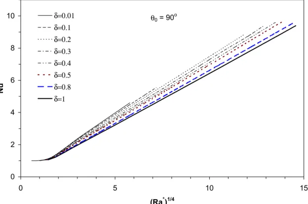
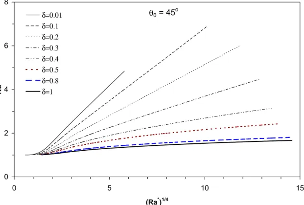
Figures 5, 6 and 7 show the variation of the Nusselt number as a function of the parameter (Ra*)1/4 for fully hemispheric domes θ0 = 90° and low profile domes θ0
= 45° and 30°, respectively. A set of gap spacings are considered, ranging from
δ = 0.01 to δ = 1. For the three dome shapes, the variation of the Nusselt number with the parameter (Ra*)1/4 shows a clear dependence on the gap spacing δ, contrary to concentric spheres [11]. This dependence is more pronounced for low profile domes than for fully hemispheric domes. For fully hemispheric domes, the Nusselt number varies linearly with (Ra*)1/4 from the onset of convection to the convection-dominated regime. However, for low profile domes, the Nusselt number exhibits a linear profile for very small gap spacings and a non-linear profile for large gap spacings. The heat transfer from the dome to the surrounding environment is thus lower for low profile domes than for fully hemispheric domes.
In view of the foregoing results, the Nusselt number may be expressed as follows:
{
* d/4}
) ( 1; max c Ra Nu = ⋅ (26)where the coefficients c and d depend on the gap spacing δ and are to be determined for each dome shape. These coefficients may be determined using regression techniques. Using the data of Figures 5 to 7 and the least-square method, one obtains the following relations for c and d:
For θ0 = 90°, d = 1, and c is given by:
3 2 0162 . 0 1129 . 0 2461 . 0 7943 . 0 − δ + δ − δ = c (27) For θ0 = 45°, 3 2 3 2 2117 . 58 1328 . 24 4185 . 2 1 736 . 49 7074 . 17 8375 . 0 8439 . 0 δ δ δ −δ +δ δ + + − + = c (28) 3 2 2 349 . 8 27 . 2 5071 . 2 1 1542 . 4 0346 . 3 1 δ δ δ δ δ + + − + − = d (29) For θ0 = 30°, 3 2 2 0183 . 26 6426 . 39 598 . 9 1 133 . 50 8836 . 9 8367 . 0 δ δ δ δ δ + + − + − = c (30) 3 2 2 4 . 123 3132 . 9 5826 . 5 1 6979 . 18 1552 . 7 0178 . 1 δ δ δ δ δ + + − + − = d (31)
The regression coefficient for the equations (27) to (31) is greater than 0.99, and the maximum error involved in estimating the coefficients c and d is less than 1%. Equations (27) to (31) are developed for the range of the Grashof number 0 < Gr ≤ 107. Equations (27) to (29) are valid for the range 0 < δ ≤ 1, and equations (30) and (31) are valid for the range 0 < δ≤ 0.3.
Figure 8 shows the variation of the estimated Nusselt numbers as a function of the parameter c(Ra*)d/4 for dome shapes θ0 = 90°, 45° and 30°. For a given
of convection to the convection-dominated regime. The maximum error in the estimated Nusselt numbers is less than 5%.
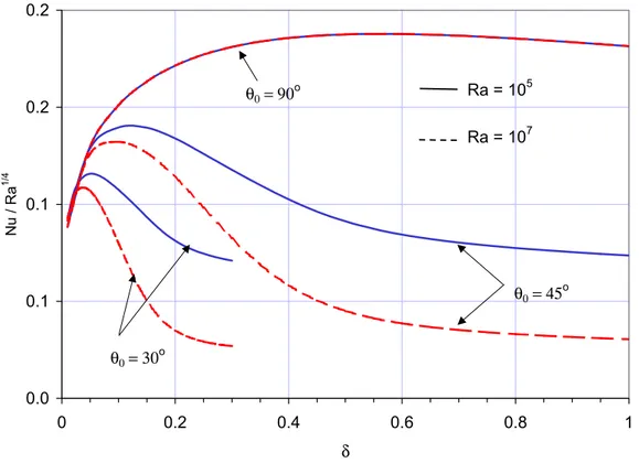
The previous figures 5 to 7 show that the Nusselt number increases with the dome truncation angle θo. However, for a given dome shape, the Nusselt number
at relatively high Rayleigh numbers increases until a maximum then decreases with the increase of the gap spacing δ. There is a critical gap spacing for which the heat transfer is maximum. To avoid this maximum heat transfer, the gap spacing should be carefully chosen. Figure 9 shows the effect of the gap spacing on the Nusselt number evaluated at Ra = 105 and 107 for dome shapes
θo = 90°, 45° and 30°. For fully hemispheric domes θo = 90°, the Nusselt number
is maximum in the range δ = 0.55 to 0.60 (flat curve), and this maximum is independent of the Rayleigh number. However, for low profile domes, the maximum Nusselt number varies with the Rayleigh number. For the range 105≤ Ra ≤ 107 the maximum Nusselt number occurs between δ = 0.1 and 0.12 for θo =
45°, and between δ = 0.037 and 0.052 for θo = 30°.
Conclusion
The steady state laminar natural convection within multi-layer domes heated from the outside was investigated for different dome shapes. The flow pattern and temperature field within the gap between layers and the convection heat transfer were presented. Correlations were developed for the convection heat transfer as a function of the dome shape and the gap spacing.
The results showed that for fully hemispheric domes, the flow pattern consists of one cell throughout the domain. However, for low profile domes, the flow pattern may consist of two cells formed near the cold and hot walls, particularly for large gap spacing. The isotherms showed that temperature stratification occurs at the middle of the gap and near the top, particularly for low profile domes with large gap spacings. This temperature stratification results in lower heat transfer to the surrounding environment. The convection heat transfer for fully hemispheric domes may reach more than 13% higher than that for low profile domes (θ0 >
45°) for small gap spacings (δ < 0.1) and more than 100% for large gap spacings (δ > 0.3). Furthermore, the convection heat transfer increases to a maximum value and then decreases with the increase of the gap spacing. The critical gap spacing that yields the maximum heat transfer increases with the dome truncation angle. The critical gap spacing for relatively high Rayleigh numbers (105 ≤ Ra ≤ 107) is the range δ = 0.55 to 0.60 (flat curve) for fully hemispheric domes θ0 = 90°, and varies between 0.1 and 0.12 for domes with θ0 = 45°, and
between 0.037 and 0.052 for domes with θ0 = 30°.
Acknowledgement
This work has been funded by the Institute for Research in Construction, National Research Council Canada, and Natural Resources Canada. The authors are very thankful for their contribution.
References
1 ASHRAE, ASHRAE Handbook – Fundamentals, ASHRAE (1997).
2 McGowan A.G., Desjarlais A.O., and Wright J.L., Simulation and Testing of Pyramid and Barrel Vault Skylights, ASHRAE Transactions: Symposia, 832-844 (1998).
3 Bishop E.H., Mack L.R., and Scanlan J.A., Heat Transfer By Natural Convection Between Concentric Spheres, Int. J. Heat Mass Transfer, 9, 649-662 (1965).
4 Scanlan J.A., Bishop E.H., and Powe R.E., Natural Convection Heat Transfer Between Concentric Spheres, Int. J. Heat Mass Transfer, 13, 1857-1872 (1970).
5 Yin S.H., Powe R.E., Scanlan J.A., and Bishop E.H., Natural Convection Flow Patterns In Spherical Annuli, Int. J. Heat Mass Transfer, 16, 1785-1795 (1973).
6 Grag V.G., Natural Convection Between Concentric Spheres, Int. J. Heat Mass Transfer, 35(8), 1935-1945 (1991).
7 Chiu C.P., and Chen W.R., Transient Natural Convection Heat Transfer Between Concentric and Vertically Eccentric Spheres, Int. J. Heat Mass Transfer, 39(2), 1439-1451 (1996).
8 Chiu C.P., and Chen W.R., Transient Natural Convection Between Concentric and Vertically Eccentric Spheres with Mixed Boundary Conditions, Heat Mass Transfer, 31, 137-143 (1996).
9 Yuan, S. W., Foundations of Fluid Mechanics, Prentice-Hall, Englewood Cliffs, N.J. (1967).
10 Patankar S.V., Numerical Heat Transfer and Fluid Flow, Hemisphere Publishing Corp., New York (1980).
11 Raithby G.D., and Hollands K.G.T., A General Method of Obtaining Approximate Solutions to Laminar and Turbulent Free Convection Problems, Advances in Heat Transfer, 11, 266-315 (1975).
Table 1 Comparison of Nusselt numbers for δ = 1 Pr = 0.7
(- Ra) Present model Garg [6] Equation (24) 1000 3000 6300 10500 14000 21000 42000 91000 1.100 1.420 1.737 1.980 2.127 2.345 2.760 3.283 1.1006 1.4213 1.7393 1.9848 2.1331 2.356 2.7761 3.311 1.00 1.261 1.518 1.7248 1.8534 2.0511 2.4392 2.9594 Pr = 6 1 500 3 000 18 000 45 000 90 000 180 000 360 000 1.195 1.448 2.360 2.914 3.408 4.005 4.721 1.1958 1.4489 2.3633 2.9237 3.4237 4.0256 4.7474 1.2531 1.4902 2.3323 2.9327 3.4877 4.1476 4.9323
θ V U R θ0 Ri Ro L Ti To y x θ V U R θ0 Ri Ro L Ti To y x
Figure 1 Schematic representation a double-layer dome.
P W S N E w e n s Ae= (∆r·r·sinθ)e An= (r2·∆θ·sinθ) n As= (r2·∆θ·sinθ) s Aw= (∆r·r·sinθ)w Primary grid Staggered grid P W S N E w e n s Ae= (∆r·r·sinθ)e An= (r2·∆θ·sinθ) n As= (r2·∆θ·sinθ) s Aw= (∆r·r·sinθ)w Primary grid Staggered grid
Figure 3 Isotherms and streamlines for fully-hemispheric domes (θ0 = 90°) at Gr
= 5 105.
Figure 4 Isotherms and streamlines for low profile domes (θ0 = 45°) at Gr = 5
0 2 4 6 8 10 0 5 10 15 (Ra*)1/4 Nu δ=0.01 δ=0.1 δ=0.2 δ=0.3 δ=0.4 δ=0.5 δ=0.8 δ=1 θ0 = 90o
Figure 5 Nusselt Number profile as a function of (Ra*)1/4 for fully-hemispheric domes (θ0 = 90°).
0 2 4 6 8 0 5 10 15 (Ra*)1/4 Nu δ=0.01 δ=0.1 δ=0.2 δ=0.3 δ=0.4 δ=0.5 δ=0.8 δ=1 θ0 = 45 o
Figure 6 Nusselt Number profile as a function of (Ra*)1/4 for low profile domes (θ0 = 45°).
0 2 4 6 0 5 10 15 (Ra*)1/4 Nu δ=0.01 δ=0.025 δ=0.05 δ=0.075 δ=0.1 δ=0.15 δ=0.2 δ=0.3 θ0 = 30 o
Figure 7 Nusselt Number profile as a function of (Ra*)1/4 for low profile domes (θ0 = 30°).
0 2 4 6 8 10 0 2 4 6 8 10 c (Ra*)1/4 Nu δ=0.01 δ=0.1 δ=0.2 δ=0.3 δ=0.4 δ=0.5 δ=0.8 δ=1 correlation θ0 = 90 o 0 2 4 6 8 0 2 4 6 c (Ra*)d/4 Nu 8 δ=0.01 δ=0.1 δ=0.2 δ=0.3 δ=0.4 δ=0.5 δ=0.8 δ=1 correlation θ0 = 45o 0 2 4 6 0 2 4 c (Ra*)d/4 Nu 6 δ=0.01 δ=0.025 δ=0.075 δ=0.05 δ=0.1 δ=0.15 δ=0.2 δ=0.3 correlation θ0 = 30o
0.0 0.1 0.1 0.2 0.2 0 0.2 0.4 0.6 0.8 1 δ Nu / Ra 1/ 4 θ0 = 90o θ0 = 45o θ0 = 30o Ra = 105 Ra = 107
Figure 9 Nusselt Number profile as a function of the dimensionless gap spacing (δ).