HAL Id: cea-02513449
https://hal-cea.archives-ouvertes.fr/cea-02513449
Submitted on 20 Mar 2020HAL is a multi-disciplinary open access archive for the deposit and dissemination of sci-entific research documents, whether they are pub-lished or not. The documents may come from teaching and research institutions in France or abroad, or from public or private research centers.
L’archive ouverte pluridisciplinaire HAL, est destinée au dépôt et à la diffusion de documents scientifiques de niveau recherche, publiés ou non, émanant des établissements d’enseignement et de recherche français ou étrangers, des laboratoires publics ou privés.
Assessment of the shielding efficiency of the HCLL
blanket for a DEMO-type fusion reactor
J. Jordanova, J.-F. Salavy, U. Fischer, P. Pereslavtsev, Y. Poitevin, A. Puma,
N. Nikolova-Todorova
To cite this version:
J. Jordanova, J.-F. Salavy, U. Fischer, P. Pereslavtsev, Y. Poitevin, et al.. Assessment of the shielding efficiency of the HCLL blanket for a DEMO-type fusion reactor. FEC2006 - Fusion Energy Conference 2006, Oct 2006, Chengdu, China. �cea-02513449�
Assessment of the shielding efficiency of the HCLL blanket
for a DEMO-type fusion reactor
J Jordanova
1, J F Salavy
2,U Fischer
3, P Pereslavtsev
3, Y Poitevin
4, A Li
Puma
2, N Nikolova-Todorova
51
Institute for Nuclear Research and Nuclear Energy, 1784 Sofia, Bulgaria
2CEA Saclay, DEN/DM2S/SERMA, 91191 Gif-sur-Yvette, France
3
Forschungszentrum Karlsruhe, Postfach 3640, 76021 Karlsruhe, Germany
4EFDA CSU Garching, Boltzmann str. 2, D 85748 Garching, Germany
5University of Shumen “Ep.Konst. Preslavski”, 9700 Shumen, Bulgaria
E-mail: jordanaj@inrne.bas.bg
Abstract. This work summarizes the results of a neutronic study on the HCLL blanket for a
DEMO-type fusion reactor. The analysis is based on three-dimensional Monte Carlo calculations using the MCNP-4C code. It comprises the assessment of the shielding efficiency in terms of the radiation loads to the superconducting TF-coils and the neutron induced production of He and H gas in the steel structure of the blanket and at locations where the welding of pipe connections is assumed. The analysis is performed utilizing three-dimensional 90- sector model representing the modular HCLL breeder blanket developed by CEA. The shielding performance of the blanket/shield/vacuum vessel system is assessed at the torus mid-plane considering three variants of a two-component shield, arranged in between the central inboard modules and the Vacuum Vessel. Estimates of radial distributions of the He and H gas production in the steel structure of the blanket are obtained and the radial depth where the re-weldability criterion for the He production <1 appm is fulfilled is identified.
Keywords: HCLL; DEMO reactor; Shielding performance; Epoxy insulator; He and H production
1. Introduction
The Helium Cooled Lithium Lead (HCLL) blanket concept is the European Fusion Technology Programme reference breeding blanket concept for a DEMO fusion power reactor specification. This blanket concept has been developed by CEA for the European Power Plant Conceptual Study (PPCS) model AB. As the PPCS model A (based on Water Cooled Lithium Lead blanket) developed by the CEA and the model B (based on Helium Cooled Pebble Bed (HCPB) blanket) and developed by FZK, this power plant model is based on near-term technological and physical extrapolations. In particular, the HCLL and the HCPB concepts share as much as possible basic technology, i.e. both blankets utilize high pressure helium gas as a coolant, low activation steel Eurofer as structural material and have common main design features, the breeder unit (BU) inserts being specific for each one of the two concepts. The HCLL blanket is based on the use of Pb-Li eutectic as tritium breeder and carrier and neutron multiplier.
Three-dimensional radiation transport calculations have been performed for the HCLL blanket for a DEMO-type fusion reactor employing the Monte Carlo code MCNP-4C [1]. The shielding efficiency of blanket/shield/vacuum vessel system has been assessed in terms of the radiation loads to the superconducting TF-coils at the torus mid-plane considering three-shield variants in between the central inboard blanket modules and vacuum vessel (VV). The helium and hydrogen production
induced by neutrons has been estimated in the blanket’s structure steel and in those locations where the re-welding of pipe connections is foreseen.
Figure 1. Three-dimensional view of the HCLL breeder blanket module. 2. Brief Description of the HCLL Blanket Module
The HCLL blanket concept uses Pb-15.6Li eutectic as a tritium breeder and carrier and neutron multiplier, low activation steel Eurofer as structural material and Helium gas as a coolant with inlet/outlet temperature of 300/5000C and 8MPa pressure. The DEMO 2002 generic blanket module [2, 3], shown in figure 1, consists of a steel box, directly cooled by the He flowing in internal channels. The first wall (FW) is armored by 0.2 cm thick W layer. The box is closed in the rear by a system of back plates (BP) ensuring the He collecting/distribution. The steel box is reinforced internally by a grid of poloidal-radial and toroidal-radial stiffening plates (SP), He cooled, to withstand the helium pressure in case of an accidental internal leak. The stiffening grid subdivides the inside of the box in radial cells, in which the Pb-15.6Li is slowly flowing, cooled by cooling units inserts. The radial cells accommodating the cooling unit inserts and Pb-15.6Li here after are referred to as breeder units (BUs).
The generic blanket module consists of 72 BUs, toroidally-poloidally disposed in 8x9 rows. The dimensions of the modules are about 200x200cm in toroidal-poloidal directions. The reference blanket module assumes 90% 6Li enrichment and has a radial length of about 100 cm (80 cm breeder unit length of which the breeder zone (BZ) thickness is 75cm and 5 cm is the thickness of the collector zone including a thin steel wall; 2.5 cm thickness of the FW and 18.2 cm thickness of the back plate). 3. Reactor Modeling and Calculation
The neutronic analyses are based on the use of the three-dimensional Monte Carlo radiation transport code MCNP-4C. A 90-torus sector model representing the modular structure of the blanket, developed by FZK [4], has been used for calculations. The DEMO reactor specifications as well as the breeding blanket modules arrangement into the reactor were not yet issued when this study took place, thus the neutronic model was devised by integrating the generic HCLL breeder blanket module into the neutronic model of the PPCS model B reactor by CEA and FZK [4]. The blanket manifolds and the high temperature shield are not taken into account in the model since detailed design neither of the blanket module collectors nor of the He and LiPb manifolds were available at the time the analysis was carried out.
A 3300 MW fusion power has been assumed for the model. A proper simulation of the spatial distribution of the D-T source neutrons was employed in calculations [4].
Radial-poloidal cross-section and radial-toroidal one at the inboard mid-plane of the MCNP model are shown in figures 2 and 3, respectively, with the essential zones pointed out. The 90-sector model includes the plasma chamber, 5 inboard modules with half their toroidal extension and 7 outboard modules with their full toroidal extension, poloidally arranged, the divertor, the vacuum vessel and the toroidal field (TF) coil at the inboard side. The model accounts for the geometry details of the blanket module as seen in figure 4, where a vertical cut of the central outboard blanket module is shown: the cooling plates, the stiffening plates, the collector zone and the thin steel plate are displayed in the figure.
Coupled neutron/gamma transport calculations have been performed employing nuclear cross-sections from the evaluated data library FENDL-2 [5]. The responses related to radiation load to the TF-coil have been assessed at the front surface of the TF-coil in order to obtain their peaking values. They were calculated with uncertainties of about 5-7 %, the lowest neutron flux error being less than 10%. Relative errors of less than 5% have been obtained for the radiation damage responses.
Figure 2. Radial-poloidal cross-section of the MCNP torus sector model. The numbers from I to V and from VI to XII indicate the inboard and outboard blanket modules, respectively. The dimensions are given in centimetres.
Figure 4. Vertical cut through the central outboard module of the MCNP model. 4. Results
4.1. Radiation Loads to the Super-conducting TF-coils
The blanket, the shield in between the blanket and VV and the VV itself constitute the integrated shield system protecting the TF-coils from the penetrating radiation. This shield system must provide sufficient shielding of the TF-coils. The critical quantities in this respect are the fast neutron fluence to the superconductor, the peak nuclear heating in the winding pack, the radiation damage to the copper stabilizer and the radiation dose absorbed by the Epoxy insulator. It should be proven, in design calculations, that the tolerable radiation loads for the super-conducting TF-coils as specified for ITER [6] are not exceeded.
Shielding calculations have been performed for the inboard mid-plane of the reactor where the shielding is most crucial due to the limited space available for the blanket and shielding system, while at the same time the neutron wall loading shows a peaking value due to the concentration of the plasma source around the mid-plane [4]. The Vacuum vessel ITER-FDR design has been utilized in calculations. It consists of a 30 cm thick shielding mixture of borated steel (60%) and water (40%) in between two SS-316 steel plates with thickness of 5 cm each. The thickness of the vacuum vessel at the inboard side is 40 cm.
Blanket with breeder zone length of 55 cm has been selected for the analyses since it ensures tritium self sufficiency at minimum thickness of the BZ [7]. In this blanket variant a 20 cm thick additional shield of Eurofer has been integrated behind the blanket modules in order to maintain the radial thickness of 100 cm (the radial length of the reference blanket modules). Thus the total thickness of the shield at the inboard mid-plane amounts to 35 cm, the blanket and the shield thickness defined in the model in that location being115 cm.
Because of the poor shielding efficiency of the blanket, an efficient shield must be placed in between the blanket and VV. The analyses presented in our previous paper [7] showed that the most crucial quantity among the radiation responses considered is the integrated absorbed dose in the Epoxy. Since more than 90% of the absorbed dose in Epoxy and of the nuclear heating in the winding pack is created by gamma-radiation, it is essential to optimise the shield between the central inboard modules and VV towards lowered gamma-rays absorbed dose in the Epoxy.
Three two-component shield variants behind the central inboard modules have been considered in the analyses, namely shield consisting of 30 cm thick Eurofer layer followed by shield of tungsten carbide composite (WC) with thickness of 5 cm, cooled by 10 vol% He, hereafter denoted as first variant ; shield of Eurofer layer of 20 cm thickness followed by 15 cm thick shield of WC, cooled by 10 vol% He, referеd as second variant and shield of 30 cm thick Eurofer layer followed by 5 cm thick shield of WC, cooled by 20vol% of water, denoted as third variant.
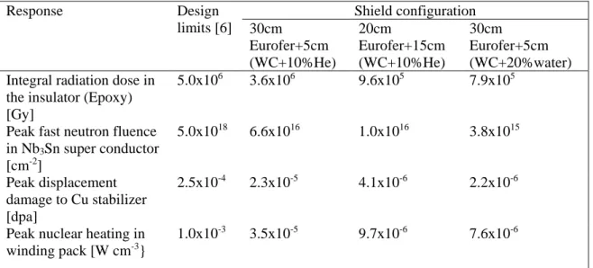
Table 1 summarizes the responses in the TF-coil based on a 3300 MW fusion power and a 20 full power years (fpy) of operation and compares the results with the radiation design limits as specified for ITER. According to the results the three variants of the two-component shield, arranged in between the central inboard modules and the vacuum vessel, provide sufficient shielding of the TF-coils in terms of radiation loads below the design limit.
Table 1. Radiation loads to the inboard TF-coil (20 fpy operation).
Response Design limits [6] Shield configuration 30cm Eurofer+5cm (WC+10%He) 20cm Eurofer+15cm (WC+10%He) 30cm Eurofer+5cm (WC+20%water) Integral radiation dose in
the insulator (Epoxy) [Gy]
5.0x10⁶ 3.6x10⁶ 9.6x10⁵ 7.9x10⁵
Peak fast neutron fluence in Nb3Sn super conductor [cm-2] 5.0x10¹⁸ 6.6x10¹⁶ 1.0x10¹⁶ 3.8x10¹⁵ Peak displacement damage to Cu stabilizer [dpa] 2.5x10⁻⁴ 2.3x10⁻⁵ 4.1x10⁻⁶ 2.2x10⁻⁶
Peak nuclear heating in winding pack [W cm-3} 1.0x10⁻³ 3.5x10⁻⁵ 9.7x10⁻⁶ 7.6x10⁻⁶ 0 50 100 150 200 106 107 108 109 1010 1011 1012 1013 1014 1015 TF-coil VV FW + blanket Shield F as t neut ron f lux ( cm -2 s -1 )
Radial distance from FW (cm) 5cm WC(10% He) 15cm WC(10% He) 5cm WC(20% water)
Figure 5. Radial profiles of fast (En>0.1 MeV) neutron flux at the inboard mid-plane for the three shield variants. In the legend is given the composition of the second shield layer.
0 50 100 150 200 107 108 109 1010 1011 1012 1013 1014 1015 TF-coil VV FW + blanket Shield T ot al neut ron f lux ( cm -2 s -1 )
Radial distance from FW (cm) 5cm WC(10% He) 15cm WC(10% He) 5cm WC(20% water)
Figure 6. Radial profiles of total neutron flux at the inboard mid-plane for the three shield variants. In the legend is given the composition of the second shield layer.
The radial profiles of the fast (En>0.1 MeV) and the total neutron fluxes calculated across the blanket\shield\vacuum vessel system are shown in figs. 5 and 6 respectively. As it is seen in the figures, the fast and total fluxes are the lowest ones at the TF-coil for the shield composed of 30 cm thick Eurofer layer and 5 cm thick WC layer cooled by 20 vol% of water. This probably is a consequence of the lowest values of the above mentioned fluxes in the shield layer adjacent to the VV, due to the combined effect of neutron slowing down by elastic scattering on H nuclei in water and inelastic scattering to levels of W nuclei, and to the neutron absorption by W nuclei.
According to the results in table 1 the third shield variant ensures the lowest radiation loads to the TF-coils. Moreover, this shield provides the best shielding performance regarding the most crucial quantity, i.e. radiation dose absorbed by the Epoxy insulator, resulting from the lowest absorbed dose created by the gamma-radiation.
Further analyses taking into account the hot shield and the blanket manifolds are foreseen in order to assess the performance of the most efficient shield variants and to evaluate the possibilities to minimize the plasma to TF-coil distance.
4.2. Helium and Hydrogen Production in Eurofer Structure
The neutron induced production of helium and hydrogen gas in the steel structure of the blanket modules and in those locations where the welding of pipe connections to permanent components is assumed have been assessed taking into account the reactions (n,α),(n,n’α), (n,p) and (n,n’p). The radial profiles of gas generation have been furthermore estimated in the steel structure of the reference blanket modules (breeder zone length of 75 cm). Calculations have been performed assuming 20 full power years of plant operation.
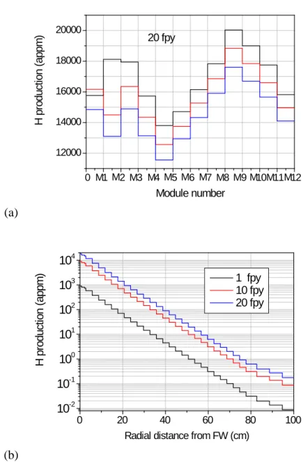
The maximum of He and H generation takes place in the steel of the FW. The largest values are located in the central inboard and outboard modules and are as follows: 3880 appm He; 18120 appm H and 4290 appm He; 20030 appm H in the inboard and outboard blanket respectively, as seen in figures 7(a) and 8(a), where the radial distributions of He and H production in the steel of the FW of the blanket modules are presented. The estimated radial distributions of He and H production in the modules steel structure, demonstrated in figures 7(a) and 8(a) respectively for the central inboard
module, show that the re-weldability criterion for the He production <1 appm [8] is fulfilled for a radial depth greater than 65 cm.
(a)
0 1 2 3 4 5 6 7 8 9 10 11 12 2500 3000 3500 4000 4500 M M M M M M M M M M M M 20 fpy H e pr oduc tion ( appm ) Module number(b)
0 20 40 60 80 100 10-3 10-2 10-1 100 101 102 103 H e pr oduc tion ( appm )Radial distance from FW (cm) 1 fpy 10 fpy 20 fpy
Figure 7. Radial distribution of helium production in steel of the FW of the blanket modules (a) and in the steel structure of the central inboard module (b).
(a)
0 1 2 3 4 5 6 7 8 9 10 11 12 12000 14000 16000 18000 20000 M M M M M M M M M M M M 20 fpy H pr oduc tion ( appm ) Module number(b)
0 20 40 60 80 100 10-2 10-1 100 101 102 103 104 H pr oduc tion ( appm )Radial distance from FW (cm)
1 fpy 10 fpy 20 fpy
Figure 8. Radial distribution of hydrogen production in steel of the FW of the blanket modules (a) and in the steel structure of the central inboard module (b).
Radial-poloidal distribution of He production in all modules is shown in figure 9, giving an overall view of the spatial distribution of He production in the FW, the structure of the blanket, BP and in Eurofer layer with thickness of 10 cm behind each blanket module.
0 1 2 3 4 5 6 7 8 9 10 11 12
0,01
0,1
1
10
100
1000
BP BZ FW M M M M M M M M M M M MH
e pr
oduc
tion (
appm
)
Module numberFigure 9. Radial-poloidal distribution of He production in Eurofer structure of the blanket modules: the FW (thick solid lines), BZ (solid lines) and BP (dot lines) are pointed out. The dashed lines denote the 10 cm thick Eurofer layer behind modules.
Table 2 lists the estimates of He and H generation in Eurofer at the rear of the blanket modules with breeder zone radial length of 75 cm and 55 cm, in the regions between the adjacent modules, where the He in/outlet pipes are welded to permanent components. Radial-poloidal view of the MCNP model at neighbouring outboard modules and the space between them with the abovementioned regions pointed out is given in figure 10. As it is seen in this table, the maximum values of the He and H contents are located in the region between outboard modules M9 and M10 for the two blanket considered, the He content there being still below the critical value for the re-weldability after 20 fpy of plant operation.
Table 2. He and H production (appm) in the regions corresponding to modules connections welding,for modules with BZ length 75 cm and 55 cm (20 fpy operation). Region
between modules
Breeder zone length 75 cm Breeder zone length 55 cm He
production
H production He production H production
M1, M2 4.4-3a) 2.1-2 2.4-2 1.1-1 M3, M4 4.1-3 1.9-2 2.2-2 1.1-1 M4, M5 1.9-3 9.4-3 1.3-2 6.1-2 M5, M6 5.9-4 2.7-3 5.8-3 2.7-2 M6, M7 1.9-3 8.8-3 1.1-2 5.1-2 M7, M8 2.1-3 1.0-2 1.6-2 7.4-2 M8, M9 3.2-3 1.5-2 2.2-2 1.0-1 M9, M10 5.1-3 2.4-2 3.3-2 1.5-1 M10, M11 1.7-3 7.8-3 1.4-2 6.4-2 M11, M12 2.1-3 9.5-3 1.5-2 7.1-2 a) Read as 4.4x10⁻³
Figure 10. Radial-poloidal view of the model at adjacent outboard modules with the space between them.
5. Conclusions
Detailed three-dimensional neutron-photon analysis of the HCLL DEMO-type blanket has been performed employing the Monte Carlo radiation transport code MCNP with a suitable torus sector model developed by FZK.
Three variants of a two-component shield of Eurofer and WC, arranged in between the central inboard modules and the vacuum vessel, have been analyzed. It was found that the three shield variants ensure radiation loads below the design limit. The best shielding performance (in terms of radiation dose absorbed by the Epoxy insulator which is considered the most crucial parameter) is provided by the shield composed of Eurofer layer followed by a WC layer cooled by water.
It is found that the re-weldability criterion for He production (<1appm) is fulfilled in the steel structure region beyond a radial depth of 65 cm considering the reference blanket and 20 full power years of plant operation.
Acknowledgements: This work has been performed under contract FU06-CT-2004-00025 with
European Atomic Energy Community.
References
[1] Briesmeister J F 2000 MCNPTM, A General Monte Carlo N-Particle Transport Code, Version 4C, LA-13709-M
[2] Poitevin Y, Boccaccini L V, Cardella A, Giancarli L, Meyder R, Diegele E, Laesser R and Benamati G 2005 Fusion Eng. Design 75-79 741
[3] Li Puma A et al 2006 Fus.Eng. Design 81 469
[4] Chen Y, Fischer U, Pereslavtsev P and Wasastjerna F 2003 The EU Power Plant Conceptual
Study – Neutronic Design Analyses for Near Term and Advanced Reactor Models Institute fur
Reaktorsicherheit Rep. FZKA 6763
[5] Paschenko A B and Wienke H 1998 FENDL/E-2.0 Evaluated Nuclear Data Library of
Neutron-nucleus Interaction Cross Sections and Photon Production Cross Sections and Photon-atom Interaction Cross Sections for Fusion Applications IAEA-NDS-175, Rev. 3
[6] ITER General Design Requirement Document (GDRD), S10 GDRD 2 95-02-10 F1.0 (June 1995)
[7] Jordanova J, Fischer U, Pereslavtsev P, Poitevin Y, Li Puma A and Nikolova-Todorova N 2006 Fusion Eng. Design 81 2213