HAL Id: hal-00707270
https://hal.archives-ouvertes.fr/hal-00707270
Preprint submitted on 12 Jun 2014
HAL is a multi-disciplinary open access
archive for the deposit and dissemination of
sci-entific research documents, whether they are
pub-lished or not. The documents may come from
teaching and research institutions in France or
abroad, or from public or private research centers.
L’archive ouverte pluridisciplinaire HAL, est
destinée au dépôt et à la diffusion de documents
scientifiques de niveau recherche, publiés ou non,
émanant des établissements d’enseignement et de
recherche français ou étrangers, des laboratoires
publics ou privés.
Flexible Product Line Derivation applied to a Model
Based Systems Engineering process
Cosmin Dumitrescu, Patrick Tessier, Camille Salinesi, Sébastien Gerard, Alain
Dauron
To cite this version:
Cosmin Dumitrescu, Patrick Tessier, Camille Salinesi, Sébastien Gerard, Alain Dauron. Flexible
Product Line Derivation applied to a Model Based Systems Engineering process. 2012. �hal-00707270�
Flexible Product Line Derivation applied to a
Model Based Systems Engineering process
Cosmin Dumitrescu1,3, Patrick Tessier2, Camille Salinesi3, Sebastien G´erard2, and
Alain Dauron1
Abstract
Systems engineering enables the successful realization of systems, focusing on defining customer needs early in the development cycle. However there is a lack of methodological support when the development of systems needs to rely on legacy system designs. Furthermore, in the automotive domain, product diversity increases system complexity so much, that reuse becomes much more difficult and time con-suming than usually. We believe a specific strategy must be adopted to prepare for reuse and to achieve systems engineering by reuse. While product line derivation provides the means to obtain single products form a collection of assets, there is still little support for integration with systems engineering practices. In this paper we present an approach which takes into account systems engineering methodolog-ical aspects in product line engineering by rendering the derivation process more flexible. We present the implementation of the tool support for our approach based on the Papyrus1 SysML modeller and exemplify the concepts through a derivation example of the electric parking brake system.
Key words: product lines, variability, derivation, model based systems engineering
RENAULT 1 Avenue du Golf, 78288 Guyancourt, France
{cosmin.dumitrescu,alain.dauron}@renault.com · CEA, LIST
Laboratory of Model Driven Engineering for Embedded Systems Point courrier 174
F91191 Gif sur Yvette, France
{patrick.tessier,sebastien.gerard}@cea.fr · Centre de Recherche en Informatique
Universit´e Paris I Panth´eon-Sorbonne 90 rue de Tolbiac, 75013 Paris France
{camille.salinesi,cosmin.dumitrescu}@univ-paris1.fr 1http://www.eclipse.org/papyrus
1.1 Introduction
Whether developing a new innovative system or reusing existing assets, engineers often need to adapt existing systems to new customers needs or deployment envi-ronments. In the case of automotive systems, the family of systems assets are useful (though not sufficient) to derive the specification for a new vehicle system project. While existing designs are used, improvements or new functionalities are introduced with each new iteration, which means that systems frequently require redesigning or altering the products.
Product line engineering derivation brings us closer to reuse, but from the systems engineering (SE) perspective we believe it needs to improve:
a) flexibility - to satisfy the need of altering existing models, derived from a family of systems
b) methodological support - to follow the traditional SE process from requirements to detailed architectural design.
We propose an approach for the configuration of a system from a family of systems, performed in several successive steps, that gradually reduce the model scope, but also enable the specification of new model items. As support for our approach we use the SysML modeller Papyrus with the Sequoia add-on for managing product lines.
The paper is structured as follows: in section 2 we present some industry and back-ground information as well as motivation behind the work. Section 2.1 presents ex-isting work related to the derivation activity. In section 3 we present the scenario that the derivation needs to follow. We also include a brief presentation of the variabil-ity modeller we use. In section 4 we describe the implementation principles and en example derivation scenario of the electric parking brake system. Finally in section 5 we conclude the paper with a short summary and outlook on future work.
1.2 Industry background and motivation
Systems engineering, which represents a development paradigm that aims at devel-oping complex systems faster and with full conformance to stakeholder require-ments, does not fully solve the problems coming from a product diversity rich en-vironment. Product lines however, present the advantage of lowering development costs by reuse of existing development assets, but its practices would need to be adapted to meet organization specific requirements and integrate existing activities. The core issue for this scenario represents the derivation and how to integrate it with development activities.
Product Linesrepresent a set of systems that share a common, managed set of as-sets throughout their entire life cycle. Two main phases are distinguished: domain engineering, concerning the development of core system assets and application en-gineering, related to product derivation.
While our research approach is based on the creation of a set of development scenar-ios for families of systems, the present article focuses on a single common case for the automotive industry: single system development, based on reusable assets from previous experiences. In general, automotive system families are not planned for a long time horizon and they are rarely the product of a dedicated, separate devel-opment cycle, with a clear ”domain (systems) engineering” phase. This is because there is a relatively short cycle of vehicle feature evolution in order to keep up with a competitive market, but reuse attempts do exist concerning issues such as stan-dardisation, definition of common software architectures, or vehicle platforms. The most important challenge, however, comes from the product range [1], or ”prod-uct diversity”, with a staggering number of different configurations for each vehicle model: 1021for the Renault ”Traffic” van for instance. The variability impacts sub-systems relative to the vehicle and eventually propagates to the component level, creating complex design and configuration problems. Furthermore, engineers need to add new model elements while each new project has its own specificities, but still relies on existing designs. In consequence we are confronted with a problem of constant evolution of family of system models. The article presents an approach to integrating product derivation in a model based systems engineering framework using SysML models. The work also represents the first stage of an effort to bring product lines closer to the MBSE world.
1.2.1 Research background
As other publications have pointed out, derivation requires methodological and tool support. It is indeed an error prone and complex task consisting in performing com-plex configuration on a set of assets of different nature and with intricate inter-relations. Furthermore, derivation methodology needs to integrate with existing or-ganization practices, in our case with the systems engineering development process as defined in [10]. In consequence the derivation of the product line needs to be regarded, as proposed by Djebbi [6], as a decision making activity, where the engi-neer might take into account existing alternatives or develop new assets to reach a completely defined product. Our objective is to allow the user to perform usual SE activities during derivation according to the framework proposed by Chal´e [3]. Con-sequently, we do not provide for now any guidance, but rather focus on rendering the process more flexible.
Deelstra points out in [4] that the derivation ”is a time-consuming and expensive activity” and provides a through investigation based on real industry case studies, that identify the sources of these problems. We are confronted with a series of sim-ilar issues, such as managing the complexity of the derivation activity or evolving the family of systems by adding new assets during derivation. In a similar manner, our derivation process consists of several iterations which gradually select and re-fine family of systems assets. The solution that we propose focuses however on a predefined framework and SysML models (Renault SysML profile), on rendering
the process flexible by introducing partial derivations and providing support for the configuration of system SysML models.
In [15] Rabiser presents an approach to support product derivation through adap-tation or augmenadap-tation of variability models. This approach is supported by the DOPLER tool suite and it explicitly captures derivation information in a decision model. The solution that we propose relies heavily on complementary information contained in the system model, such as predefined stakeholders or specific points of view. We do not capture role information for example in the variability model, as in our context this kind of information can be provided by family of system models. At the same time the SE framework provides an asset collection structure which proves useful during derivation. The problem of finding the right assets during derivation is also pointed out by Hunt [11] who provides an evaluation of the impact of orga-nizing the asset base in different ways.
Product diversity is the cause of an outstanding complexity increase in both auto-motive software and system domain, as suggested by Astesana [1] and Tischer [20]. Variability and complexity impact all aspects of the organization activity, from mar-keting, customer interaction (through online configurators), engineering (through the design of families of systems and capitalization) and eventually manufacturing in the plant and logistics.
1.3 Context and needs
In order to understand the industry needs, we have developed a set of systems engi-neering scenarios involving the reuse of assets (e.g., requirements, solution designs, models): synchronized systems development, integration of a single system into a product line, merge of two product lines, derivation of a single system from a sys-tem family, development of a single syssys-tem based on reuse (through derivation). We have chosen the latter as a nominal case, that we exploit in this paper to define our goals and constraints, which are articulated around the following statements:
• Starting working context of the project:
1. We assume that the family of systems (FoS) model is defined a priori; 2. We assume that there is sufficient detail in the FoS description to derive a
single complete system specification, as a consequence of previous develop-ment efforts
3. As process input, we assume that a variability definition of the system con-text (environment, technical concon-text and client services) is ”inherited” from the upper level system analysis (e.g. vehicle variability propagates to subsys-tems).
• In addition to the typical activities of the systems engineering process, we need to take into account other activities related to reuse:
1. The approach shall enable identification of system scope reuse opportunities: fort that the engineer has to choose existing assets in relation to high level
requirements, environment variability, technical context and commercial of-fer. These assets, related to the operational analysis viewpoint of the systems engineering process, define and place the system context and its use cases in relation to previously developed systems and and orient subsequent activities towards reuse.
2. The approach shall enable identification of solution reuse opportunities. The engineer is required to choose among potential solutions by performing con-cept synthesis/analysis and trade-off analysis. He may either decide to go for an existing solution, matching a similar ”system scope” and use cases, either develop a new architecture, to satisfy new requirements or to provide more efficient solutions to existing problem definitions.
3. The approach shall enable identification of component and module reuse op-portunities. The engineer is required to match the system architecture with existing solutions and take advantage of existing components or modules. Thus, in a top-down approach, a common architecture can lead to reusable components. In the opposite case, a bottom up-approach may allow the engi-neer to match and combine existing components and modules to realize the required system functions.
• The output of the process consists of:
1. Allocation of requirements to components for the selected configurations. 2. Variability description for each component belonging to the selected
config-urations.
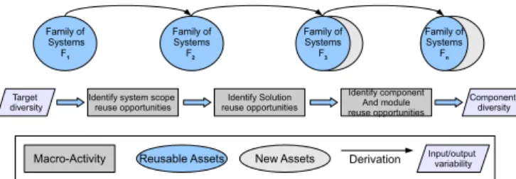
The statements that we presented are compatible with the general systems en-gineering process described in [3]. Figure 1.1 illustrates the relation between the activities presented above and system assets : with each reuse decision, variability contained in the description of the family of systems is solved, leading to an inter-mediate and partial configuration of the system.
Fig. 1.1 Reuse related activities in the development process.
Meanwhile, it is possible to introduce new assets for each partial configuration. The target diversity is specified, as input to the process, using the Renault documen-tary language[1]. The key activities where reuse opportunities should be evaluated correspond to transitions between the different viewpoints: operational, functional and physical [3], that correspond to our reference model-based systems engineering architecture framework. At a more general level, these transitions correspond to the
passage from higher to lower levels of abstraction (to a more detailed description of the problem) or to a subsystem or subcomponent (e.g. environment to vehicle or ve-hicle to subsystem). Of course, if the requirements offset is too important in respect to the family of systems and if new requirements cannot be satisfied by existing so-lutions, the activities will be oriented towards development, instead of reuse. A partial system configuration represents a collection of assets that includes vari-ability and is obtained through partial resolution of varivari-ability contained in the fam-ily of systems definition.
We define target diversity as a partial system configuration of a system that refers only to: the system environment, the system technical context and customer services (commercial offer). It represents the diversity of customer needs that the system shall cover and the diversity of environments a system shall be used in.
Even if most of the system and variability assets are already defined before starting the derivation, the target diversity may have a larger scope than what is already de-fined. In consequence variability creation and resolution activities may be performed even during the development of the same product.
1.3.1 The Sequoia tool
The goal of the Sequoia approach [19], developed by the CEA LIST is to help de-signers to build product lines based on UML/SysML models. Among its different functionalities, Sequoia supports variability modelling, variability propagation [18], and generation of a decision model.
Variability is expressed through the definition of a UML profile. To specify an op-tional element, the designer simply adds the stereotype VariableElement to the item. The stereotype ElementGroup introduces additional information through its proper-ties, such as constraints between variable elements. In Sequoia, the decision model is used as a guide enabling to analyse all available variants and paths leading to a completely defined product. Once the derivation activity is launched, the choices described by the decision model are proposed to the user as a series of questions. The output of this process is a completely defined product and the user is not able to make any kind of modification to the initial model until the derivation step is over.
1.4 Results and implementation
We have imagined two scenarios for the derivation of a single system with the Se-quoia tool, which are compatible with the context and process related elements pre-sented in section 1.3.
# Scenario A (Derivation based on system viewpoints or stakeholders): we con-sider the derivation process follows the development process and a certain se-quence of choices performed to gradually reduce the model scope.
# Scenario B (Non-functional requirements as criteria for derivation): we take into account a derivation process where the final product has to satisfy certain non functional properties (e.g. weight, cost)
We can achieve these scenarios by performing several partial configuration on the family of systems model. In consequence, each configuration step should take into account only a part of the variable elements, while the rest are to be kept in the resulting model. At the same time the engineer should be able to modify or define new variable or non variable model items between stages.
1.4.1 Partial system configuration
In order to perform a partial configuration we rely on the description of a CSP prob-lem (classically defined as a triplet P= (X,D,C), for any variable xi∈ X, D(xi) is the domain of xi, while c1..n∈ C a set of constraints related to x1..k). The tool Sequoia
allows the user to select among a list of predefined constraints: implication, equiv-alence, AtLeastOne, AllPosibilities, Alternative, or to define a custom expression. Each variable is related to a model item, which is stereotyped as variable, meaning the item can be present, absent or replaceable.
A viewpoint (on a system) is an abstraction that yields a specification of the whole system restricted to a particular set of concerns. [8] Supposeγdenotes a viewpoint restricted to a set of concernsφγ= {ϕ1..ϕn}. We suppose there is a user defined rule of correspondence fγ:φγ → X, which associates to each concernϕ a set of
variables x from X. An assignment gV is a function that maps any xi∈ X to a value
in D(xi) ∪ {#}, using the symbol ”#” to denote that the variable has not yet been
assigned a value from D.
0. Define family of system concernsγ for derivation 1. Define viewpointφγ.
2. Determine Vd= fγ(φγ) the set of variables for par-tial derivation.
3. Assign values from D(xi) = {0; 1} for each vari-able xiuntil g is a complete assignment on Vd, such as∀xi∈ Vd,xi̸= #.
4. For each xi= 0 remove model items. 5. Allow the user to define new model items. 6. Regenerate CSP problem : P′= (X′,D,C′), where X′= X \Vdand C’ the set of related constraints.
1.4.2 Towards a scenario based system derivation, The Sequoia-R
profile
The Sequoia profile was modified to support partial derivation, by introducing con-cepts that enable filtering constraints in respect to particular concerns defined by the user, as described in table 1.1. The concepts that were added are DecisionCriteria and ProductCriteria.
The concept DecisionCriteria is used to gather the variation groups, that describe constraints between several system assets or independent variable assets, that are not linked by the system specified to any other variation groups. It provides a way to map specific user concerns for derivation to configuration variables and constraints. We define variation group categories depending on the systems engineering de-velopment process phases and system stakeholders. For example, we can define a series of DecisionCriteria which follow the different levels of analysis of a system, or DecisionCriteria which regroup choices concerning a certain development phase: requirement elicitation, technical requirement definition, solution alternatives, func-tional architecture definition physical architecture definition, etc.
One of the ways the system can be partially derived, is to associate the different stakeholders (stakeholder model element) included in the development process and in the system scope. We can perform for example a derivation where we resolve all customer or marketing variations but leave open all detailed design decisions or pa-rameters. A variation group can be referenced by multiple DecisionCriteria, which allows for different aspects to be taken into account in the creation of a decision model for the system family.
The element ProductCriteria was added to express non-functional properties of the
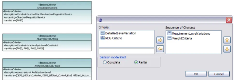
Fig. 1.2 The stereotypes DecisionCriteria and ProductCriteria
products. For example, it can contain an integer, a string or a boolean value which can be associated to the product.
1.4.3 The Electric Parking Brake Case Study
The electric parking brake (EPB) application is a variation of the classical, purely mechanical, parking brake which ensures vehicle immobilization when the driver
brings the vehicle to a full stop and leaves the vehicle. We have chosen this exam-ple for its simplicity in respect to other automotive systems and because it contains many variations from the requirements to solution design and component implemen-tation. Table 1.2 presents the main variations which were identified in the conception of this system, relative to the viewpoints specific to the Renault systems engineering process [3].
System
View-Point Occurrence place Variation point V Id Variants
Operational High Level Brake Lock BL1 Automatic
Analysis Customer BL2 Manual
Requirements Brake Release BR1 Automatic
BR2 Manual
Hill Start Assistance HSA Present
System Context GearBox GB1 Automatic
GB2 Manual
Clutch Pedal CP Present
Vehicle Trailer VT Present
System Environement Regulation Reg1 EU
Reg2 US
Functional Functional Braking Strategy BS1 Dynamic
Viewpoint Decomposition BS2 Comfort
BS3 Static Effort Monitor EMon1 Permanent On Engine Stop Emon2 Temporary Engineering Technical Solution Main Design PC Puller Cable
Decisions Alternative CA Caliper Actuators
Physical Physical Electrical DCM DC motor
Viewpoint Decomposition Action ACT Actuators
Table 1.2 Electric parking brake system main variations
For the sake of simplicity we do not present all variations relative to the EPB system, but only the most representative ones. Other variations are present, such as specific behaviour relative to the vehicle model or range, depending on the config-uration of CAN bus messages, vehicle weight, etc. As an observation, we point out that all variations occurring in the operational viewpoint propagate towards the be-haviour and physical implementation of the system. At the same time new variations may appear due to alternative design solutions during the problem solving process.
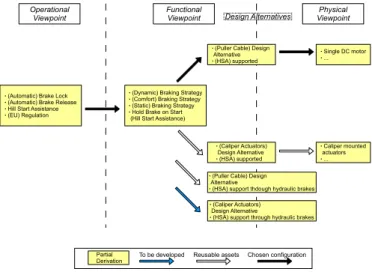
These variants induce alternative representations of the SysML system model. We
Fig. 1.3 The Electric Parking Brake system main design alternatives
to variability, that are supported by its Sequoia add-on [18]. (e.g. VT excludes HSA; GB1 or GB2, BS2 requires CA)
1.4.4 Example of derivation scenario for the EPB
We have tested a derivation scenario, on the electric parking brake example, accord-ing to the implementation presented in section 1.4.2 in the tool Sequoia for manag-ing model based product lines. In order to create the criteria sequence, we consider that the family of systems model is already available along with the required vari-ability. The first step from here, is to model the derivation criteria within the FoS
Fig. 1.4 Derivation scenarios for the EPB system
model. After modelling all needed derivation criteria, we are able to customize the derivation process by selection of the appropriate order and desired criteria through a specific model wizard.
Figure 1.4 describes a sequence of choices that lead to the configuration of a single EPB system model. Two types of variability can be seen: one issued by stakeholders or customer requirements (the customer being represented by the marketing repre-sentative), and the other belonging to the solution domain, relative to design alterna-tives. Thus it is possible to reach different designs on the solution level, depending on the selected path and on the initial configuration on problem level. However some of the explored alternatives may not yet be implemented (e.g. a new design leading to cost reduction, increased performance, based on component availability etc.), and reusing assets will only be possible for the operational viewpoints and stakeholder requirements in this case.
The dialogue shown in figure 1.5 enables the user to specify the kind of model gen-eration,partial or complete, along with a sequence of criteria that will impact the order of proposed choices. In the case where the decision criteria only correspond
to a subset of all variation groups, after generating a decision model, only the linked choices will be proposed during the derivation phase. The result of a derivation based on a partial decision model will be a new family of systems model containing less variations as the previous one, but not the complete specification of the product.
Fig. 1.5 Configuration of the partial derivation stages.
In the case of a complete derivation, the tool will search the variation groups which were not selected in the derivation sequence, and will propose them as deci-sions after the treatment of the variations linked to the selected criteria.
In this way, we are not only able to impose a desired sequence of choices, in ac-cordance to the SE process, but also to create several iterations of derivation and modelling, where new assets can be introduced or removed. It allows at the same time to distribute the derivation process between several actors, which could have different preoccupations, without the need to know the details of the product line model.
Since the derivations are successive, there is no problem concerning conflicting de-cisions, because the generation model is regenerated after each partial derivation. In the case where the derivations are made in parallel however, conflicts can appear, but this aspect is treated (at least for now) on the methodology level, by following a predefined flow of actions.
1.5 Conclusion and future work
We presented in this paper an approach to integrate model based systems engineer-ing activities with product derivation and to render the configuration process more flexible, by reducing complexity and allowing the introduction of new model items at each step of the configuration.
Because the development of systems in the automotive domain often relies on reuse, but requires modification or evolution of previous designs, the process of family of systems derivation needs to address flexibility. Being difficult and error prone, derivation methodological support reduces significantly the possible paths of con-figuration and simplifies the overall process. We also presented the implementation
realized in order to support this approach through the tool Sequoia for managing product lines.
Our future work includes the adoption of an expressive orthogonal variability model that would ease manipulation of variable assets. It includes modelling of automotive domain specific diversity and interaction with the Renault configuration language [1]. We also intend to investigate the issue of guidance during product line deriva-tion and how this could benefit from systems engineering trade-off analysis in the selection or development of variants. While the current approach allows the speci-fication of new assets, we would have to take into account evolution, maintenance and tracking changes for family of system model.
References
1. Astesana, J.M., Cosserat, L., Fargier, H.: Constraint-based Modeling and Exploitation of a Vehicle Range at Renault’s: Requirement analysis and complexity study. Workshop on Con-figuration. p. 33 (2010).
2. Bosch, J.: Maturity and evolution in software product lines: Approaches, artefacts and organi-zation. Software Product Lines. 247-262 (2002).
3. Chal´e G´ongora, H.G., Dauron, A., Gaudr´e, T.: A Commonsense-Driven Architecture Frame-work. Part 1: A Car Manufacturers (na¨ıve) Take on MBSE. INCOSE 2012.
4. Deelstra, S., Sinnema, M., Bosch, J.: Experiences in software product families: Problems and issues during product derivation. Software Product Lines. 120-122 (2004).
5. Deelstra, S., Sinnema, M., Bosch, J.: Product derivation in software product families: a case study. Journal of Systems and Software. 74, 173194 (2005).
6. Djebbi, O., Salinesi, C., Diaz, D.: Deriving Product Line Requirements: the RED-PL Guidance Approach. Presented at the December (2007).
7. Djebbi, O., Salinesi, C.: RED-PL, a method for deriving product requirements from a prod-uct line requirements model. Proceedings of the 19th international conference on Advanced information systems engineering. pp. 279293 (2007).
8. IEEE Recommended Practice for Architectural Description for Software-Intensive Systems. IEEE Standard 1471-2000, Institute for Electrical and Electronics Engineering, New York. 9. Gomaa, H., Shin, M.E.: Automated software product line engineering and product derivation.
System Sciences, 2007. HICSS 2007. 40th Annual Hawaii International Conference on. p. 285a-285a (2007).
10. Haskins, C.: Systems engineering handbook. INCOSE. Version. 3.2, (2010).
11. Hunt, J.M.: Organizing the asset base for product derivation. Software Product Line Confer-ence, 2006 10th International. pp. 6574 (2006).
12. McGregor, J.D.: Preparing for Automated Derivation of Products in a Software Product Line. Carnegie Mellon Software Engineering Institute, Pittsburgh, PA 15213–3890 (2005). 13. OLeary, P., Mc Caffery, F., Richardson, I., Thiel, S.: Towards agile product derivation in
soft-ware product line engineering. (2009).
14. Perrouin, G., Klein, J., Guelfi, N., J´ez´equel, J.-M.: Reconciling Automation and Flexibility in Product Derivation. Presented at the September (2008).
15. Rabiser, R., Grunbacher, P., Dhungana, D.: Supporting Product Derivation by Adapting and Augmenting Variability Models. Presented at the September (2007).
16. Rabiser, R., Dhungana, D.: Integrated support for product configuration and requirements en-gineering in product derivation. Software Enen-gineering and Advanced Applications, 2007. 33rd EUROMICRO Conference on. pp. 219-228 (2007).
17. Svahnberg, M., Bosch, J.: Evolution in software product lines. 3rd International Workshop on Software Architectures for Products Families (IWSAPF-3) (2000).
18. Tessier, P., G´erard, S., Terrier, F., Geib, J.M.: Using variation propagation for model-driven management of a system family. Software Product Lines. 222-233 (2005).
19. Tessier, P., Servat, D., G´erard, S.: Variability management on behavioral models. VaMoS Workshop. pp. 121-130 (2008).
20. Tischer, C., Muller, A., Mandl, T., Krause, R.: Experiences from a Large Scale Software Prod-uct Line Merger in the Automotive Domain. Presented at the August (2011).