ESP8266 Arduino Core Documentation
Release 2.4.0
Ivan Grokhotkov
Contents:
1 Installing 1
1.1 Boards Manager . . . 1
1.2 Using git version . . . 2
2 Reference 5 2.1 Digital IO. . . 5
2.2 Analog input . . . 6
2.3 Analog output . . . 6
2.4 Timing and delays . . . 6
2.5 Serial . . . 6 2.6 Progmem . . . 7 3 Libraries 9 3.1 WiFi(ESP8266WiFi library) . . . 9 3.2 Ticker . . . 9 3.3 EEPROM . . . 9
3.4 I2C (Wire library) . . . 10
3.5 SPI . . . 10
3.6 SoftwareSerial . . . 10
3.7 ESP-specific APIs . . . 10
3.8 mDNS and DNS-SD responder (ESP8266mDNS library). . . 11
3.9 SSDP responder (ESP8266SSDP) . . . 11
3.10 DNS server (DNSServer library). . . 11
3.11 Servo . . . 12
3.12 Other libraries (not included with the IDE) . . . 12
4 Filesystem 15 4.1 Flash layout . . . 15
4.2 File system limitations . . . 16
4.3 Uploading files to file system . . . 16
4.4 File system object (SPIFFS) . . . 17
4.5 Filesystem information structure . . . 18
4.6 Directory object (Dir) . . . 19
4.7 File object . . . 19
5 ESP8266WiFi library 21 5.1 Introduction . . . 21
5.4 What’s Inside? . . . 29 6 OTA Updates 33 6.1 Introduction . . . 33 6.2 Arduino IDE . . . 34 6.3 Web Browser . . . 42 6.4 HTTP Server . . . 45 6.5 Stream Interface . . . 47 6.6 Updater class . . . 47 7 Boards 49 7.1 Adafruit HUZZAH ESP8266 (ESP-12) . . . 49
7.2 ESPresso Lite 1.0. . . 49 7.3 ESPresso Lite 2.0. . . 49 7.4 Phoenix 1.0 . . . 49 7.5 Phoenix 2.0 . . . 50 7.6 NodeMCU 0.9 . . . 50 7.7 NodeMCU 1.0 . . . 50 7.8 Olimex MOD-WIFI-ESP8266-DEV . . . 50 7.9 Olimex MOD-WIFI-ESP8266 . . . 51 7.10 Olimex ESP8266-EVB. . . 51
7.11 SparkFun ESP8266 Thing . . . 51
7.12 SweetPea ESP-210 . . . 51
7.13 ESPino . . . 51
7.14 WifInfo . . . 52
7.15 Generic ESP8266 modules . . . 52
7.16 Serial Adapter . . . 52
7.17 Minimal Hardware Setup for Bootloading and Usage . . . 53
7.18 ESP to Serial . . . 53
7.19 Minimal . . . 54
7.20 Improved Stability . . . 55
7.21 Boot Messages and Modes . . . 55
7.22 Generic ESP8285 modules . . . 56
7.23 WeMos D1 . . . 56
7.24 WeMos D1 mini . . . 56
7.25 ESPino (WROOM-02 Module) by ThaiEasyElec . . . 56
7.26 gen4-IoD Range by 4D Systems . . . 57
8 FAQ 59 8.1 I am getting “espcomm_sync failed” error when trying to upload my ESP. How to resolve this issue? 59 8.2 Why esptool is not listed in “Programmer” menu? How do I upload ESP without it? . . . 59
8.3 My ESP crashes running some code. How to troubleshoot it? . . . 59
8.4 This Arduino library doesn’t work on ESP. How do I make it working? . . . 60
8.5 In the IDE, for ESP-12E that has 4M flash, I can choose 4M (1M SPIFFS) or 4M (3M SPIFFS). No matter what I select, the IDE tells me the maximum code space is about 1M. Where does my flash go? 60 8.6 I have observed a case when ESP.restart() doesn’t work. What is the reason for that? . . . 60
8.7 How to resolve “Board generic (platform esp8266, package esp8266) is unknown” error?. . . 60
9 Exception Causes (EXCCAUSE) 61 10 Debugging 63 10.1 Introduction . . . 63
10.2 Informations . . . 65
11 Stack Dumps 67
11.1 Introduction . . . 67
12 Using Eclipse with Arduino ESP8266 69 12.1 What to Download . . . 69
12.2 Setup Arduino . . . 69
12.3 Setup Eclipse . . . 69
12.4 Eclipse wont build . . . 70
13 Changelog 71 13.1 2.3.0 . . . 71 13.2 2.2.0 . . . 73 13.3 2.0.0 . . . 75 13.4 1.6.4-673-g8cd3697 . . . 77 13.5 1.6.4-628-g545ffde . . . 77 iii
CHAPTER
1
Installing
Boards Manager
This is the suggested installation method for end users.
Prerequisites
• Arduino 1.6.8, get it fromArduino website. • Internet connection
Instructions
• Start Arduino and open Preferences window.
• Enter http://arduino.esp8266.com/stable/package_esp8266com_index.json into Addi-tional Board Manager URLsfield. You can add multiple URLs, separating them with commas.
• Open Boards Manager from Tools > Board menu and find esp8266 platform. • Select the version you need from a drop-down box.
• Click install button.
• Don’t forget to select your ESP8266 board from Tools > Board menu after installation.
You may optionally use staging boards manager package link: http://arduino.esp8266.com/staging/ package_esp8266com_index.json. This may contain some new features, but at the same time, some things might be broken.
Using git version
This is the suggested installation method for contributors and library developers.
Prerequisites
• Arduino 1.6.8 (or newer, if you know what you are doing) • git
• python 2.7
• terminal, console, or command prompt (depending on you OS) • Internet connection
Instructions
• Open the console and go to Arduino directory. This can be either your sketchbook directory (usually <Documents>/Arduino), or the directory of Arduino application itself, the choice is up to you.
• Clone this repository into hardware/esp8266com/esp8266 directory. Alternatively, clone it elsewhere and create a symlink, if your OS supports them.
cd hardware mkdir esp8266com cd esp8266com
git clone https://github.com/esp8266/Arduino.git esp8266
You should end up with the following directory structure:
Arduino | --- hardware | --- esp8266com | --- esp8266 | --- bootloaders --- cores --- doc --- libraries --- package --- tests --- tools --- variants --- platform.txt --- programmers.txt --- README.md --- boards.txt --- LICENSE
• Download binary tools
cd esp8266/tools python get.py
ESP8266 Arduino Core Documentation, Release 2.4.0
• Restart Arduino
CHAPTER
2
Reference
Digital IO
Pin numbers in Arduino correspond directly to the ESP8266 GPIO pin numbers. pinMode, digitalRead, and digitalWritefunctions work as usual, so to read GPIO2, call digitalRead(2).
Digital pins 0—15 can be INPUT, OUTPUT, or INPUT_PULLUP. Pin 16 can be INPUT, OUTPUT or INPUT_PULLDOWN_16. At startup, pins are configured as INPUT.
Pins may also serve other functions, like Serial, I2C, SPI. These functions are normally activated by the corresponding library. The diagram below shows pin mapping for the popular ESP-12 module.
Fig. 2.1: Pin Functions
Digital pins 6—11 are not shown on this diagram because they are used to connect flash memory chip on most modules. Trying to use these pins as IOs will likely cause the program to crash.
Note that some boards and modules (ESP-12ED, NodeMCU 1.0) also break out pins 9 and 11. These may be used as IO if flash chip works in DIO mode (as opposed to QIO, which is the default one).
Pin interrupts are supported through attachInterrupt, detachInterrupt functions. Interrupts may be at-tached to any GPIO pin, except GPIO16. Standard Arduino interrupt types are supported: CHANGE, RISING, FALLING.
Analog input
ESP8266 has a single ADC channel available to users. It may be used either to read voltage at ADC pin, or to read module supply voltage (VCC).
To read external voltage applied to ADC pin, use analogRead(A0). Input voltage range is 0 — 1.0V.
To read VCC voltage, use ESP.getVcc() and ADC pin must be kept unconnected. Additionally, the following line has to be added to the sketch:
ADC_MODE(ADC_VCC);
This line has to appear outside of any functions, for instance right after the #include lines of your sketch.
Analog output
analogWrite(pin, value)enables software PWM on the given pin. PWM may be used on pins 0 to 16. Call analogWrite(pin, 0)to disable PWM on the pin. value may be in range from 0 to PWMRANGE, which is equal to 1023 by default. PWM range may be changed by calling analogWriteRange(new_range).
PWM frequency is 1kHz by default. Call analogWriteFreq(new_frequency) to change the frequency.
Timing and delays
millis()and micros() return the number of milliseconds and microseconds elapsed after reset, respectively. delay(ms) pauses the sketch for a given number of milliseconds and allows WiFi and TCP/IP tasks to run. delayMicroseconds(us)pauses for a given number of microseconds.
Remember that there is a lot of code that needs to run on the chip besides the sketch when WiFi is connected. WiFi and TCP/IP libraries get a chance to handle any pending events each time the loop() function completes, OR when delayis called. If you have a loop somewhere in your sketch that takes a lot of time (>50ms) without calling delay, you might consider adding a call to delay function to keep the WiFi stack running smoothly.
There is also a yield() function which is equivalent to delay(0). The delayMicroseconds function, on the other hand, does not yield to other tasks, so using it for delays more than 20 milliseconds is not recommended.
Serial
Serialobject works much the same way as on a regular Arduino. Apart from hardware FIFO (128 bytes for TX and RX) HardwareSerial has additional 256-byte TX and RX buffers. Both transmit and receive is interrupt-driven. Write and read functions only block the sketch execution when the respective FIFO/buffers are full/empty.
ESP8266 Arduino Core Documentation, Release 2.4.0
Serialuses UART0, which is mapped to pins GPIO1 (TX) and GPIO3 (RX). Serial may be remapped to GPIO15 (TX) and GPIO13 (RX) by calling Serial.swap() after Serial.begin. Calling swap again maps UART0 back to GPIO1 and GPIO3.
Serial1uses UART1, TX pin is GPIO2. UART1 can not be used to receive data because normally it’s RX pin is occupied for flash chip connection. To use Serial1, call Serial1.begin(baudrate).
If Serial1 is not used and Serial is not swapped - TX for UART0 can be mapped to GPIO2 instead by calling Serial.set_tx(2)after Serial.begin or directly with Serial.begin(baud, config, mode, 2). By default the diagnostic output from WiFi libraries is disabled when you call Serial.begin. To enable de-bug output again, call Serial.setDede-bugOutput(true). To redirect dede-bug output to Serial1 instead, call Serial1.setDebugOutput(true).
You also need to use Serial.setDebugOutput(true) to enable output from printf() function.
Both Serial and Serial1 objects support 5, 6, 7, 8 data bits, odd (O), even (E), and no (N) parity, and 1 or 2 stop bits. To set the desired mode, call Serial.begin(baudrate, SERIAL_8N1), Serial. begin(baudrate, SERIAL_6E2), etc.
A new method has been implemented on both Serial and Serial1 to get current baud rate setting. To get the current baud rate, call Serial.baudRate(), Serial1.baudRate(). Return a int of current speed. For example
// Set Baud rate to 57600 Serial.begin(57600);
// Get current baud rate
int br = Serial.baudRate();
// Will print "Serial is 57600 bps" Serial.printf("Serial is %d bps", br);
I’ve done this also for official ESP8266Software Seriallibrary, see thispull request.
Note that this implementation is only for ESP8266 based boards, and will not works with other Arduino boards.
Progmem
The Program memory features work much the same way as on a regular Arduino; placing read only data and strings in read only memory and freeing heap for your application. The important difference is that on the ESP8266 the literal strings are not pooled. This means that the same literal string defined inside a F("") and/or PSTR("") will take up space for each instance in the code. So you will need to manage the duplicate strings yourself.
There is one additional helper macro to make it easier to pass const PROGMEM strings to methods that take a __FlashStringHelpercalled FPSTR(). The use of this will help make it easier to pool strings. Not pooling strings... String response1; response1 += F("http:"); ... String response2; response2 += F("http:");
using FPSTR would become...
const char HTTP[] PROGMEM = "http:"; ... { String response1; response1 += FPSTR(HTTP); ... String response2; response2 += FPSTR(HTTP); } 8 Chapter 2. Reference
CHAPTER
3
Libraries
WiFi(ESP8266WiFi library)
ESP8266WiFi library has been developed basing on ESP8266 SDK, using naming convention and overall functionality philosophy of theArduino WiFi Shield library. Over time the wealth Wi-Fi features ported from ESP8266 SDK to this library outgrew the APIs of WiFi Shield library and it became apparent that we need to provide separate documentation on what is new and extra.
ESP8266WiFi library documentation.
Ticker
Library for calling functions repeatedly with a certain period. Two examples included.
It is currently not recommended to do blocking IO operations (network, serial, file) from Ticker callback functions. Instead, set a flag inside the ticker callback and check for that flag inside the loop function.
Here is library to simplificate Ticker usage and avoid WDT reset:TickerScheduler
EEPROM
This is a bit different from standard EEPROM class. You need to call EEPROM.begin(size) before you start reading or writing, size being the number of bytes you want to use. Size can be anywhere between 4 and 4096 bytes. EEPROM.writedoes not write to flash immediately, instead you must call EEPROM.commit() whenever you wish to save changes to flash. EEPROM.end() will also commit, and will release the RAM copy of EEPROM contents. EEPROM library uses one sector of flash located just after the SPIFFS.
Three examples included.
I2C (Wire library)
Wire library currently supports master mode up to approximately 450KHz. Before using I2C, pins for SDA and SCL need to be set by calling Wire.begin(int sda, int scl), i.e. Wire.begin(0, 2) on ESP-01, else they default to pins 4(SDA) and 5(SCL).
SPI
SPI library supports the entire Arduino SPI API including transactions, including setting phase (CPHA). Setting the Clock polarity (CPOL) is not supported, yet (SPI_MODE2 and SPI_MODE3 not working).
The usual SPI pins are: • MOSI = GPIO13 • MISO = GPIO12 • SCLK = GPIO14
There’s an extended mode where you can swap the normal pins to the SPI0 hardware pins. This is enabled by calling SPI.pins(6, 7, 8, 0)before the call to SPI.begin(). The pins would change to:
• MOSI = SD1 • MISO = SD0 • SCLK = CLK • HWCS = GPIO0
This mode shares the SPI pins with the controller that reads the program code from flash and is controlled by a hardware arbiter (the flash has always higher priority). For this mode the CS will be controlled by hardware as you can’t handle the CS line with a GPIO, you never actually know when the arbiter is going to grant you access to the bus so you must let it handle CS automatically.
SoftwareSerial
An ESP8266 port of SoftwareSerial library done by Peter Lerup (@plerup) supports baud rate up to 115200 and multi-ples SoftwareSerial instances. Seehttps://github.com/plerup/espsoftwareserialif you want to suggest an improvement or open an issue related to SoftwareSerial.
ESP-specific APIs
Some ESP-specific APIs related to deep sleep, RTC and flash memories are available in the ESP object.
ESP.deepSleep(microseconds, mode) will put the chip into deep sleep. mode is one of WAKE_RF_DEFAULT, WAKE_RFCAL, WAKE_NO_RFCAL, WAKE_RF_DISABLED. (GPIO16 needs to be tied to RST to wake from deepSleep.)
ESP.rtcUserMemoryWrite(offset, &data, sizeof(data)) and ESP. rtcUserMemoryRead(offset, &data, sizeof(data)) allow data to be stored in and retrieved from the RTC user memory of the chip respectively. Total size of RTC user memory is 512 bytes, so offset + sizeof(data)shouldn’t exceed 512. Data should be 4-byte aligned. The stored data can be retained between deep sleep cycles. However, the data might be lost after power cycling the chip.
ESP8266 Arduino Core Documentation, Release 2.4.0
ESP.restart()restarts the CPU.
ESP.getResetReason()returns a String containing the last reset reason in human readable format. ESP.getFreeHeap()returns the free heap size.
ESP.getChipId()returns the ESP8266 chip ID as a 32-bit integer. ESP.getCoreVersion()returns a String containing the core version. ESP.getSdkVersion()returns the SDK version as a char.
ESP.getCpuFreqMHz()returns the CPU frequency in MHz as an unsigned 8-bit integer. ESP.getSketchSize()returns the size of the current sketch as an unsigned 32-bit integer. ESP.getFreeSketchSpace()returns the free sketch space as an unsigned 32-bit integer. ESP.getSketchMD5()returns a lowercase String containing the MD5 of the current sketch. ESP.getFlashChipId()returns the flash chip ID as a 32-bit integer.
ESP.getFlashChipSize()returns the flash chip size, in bytes, as seen by the SDK (may be less than actual size).
ESP.getFlashChipRealSize()returns the real chip size, in bytes, based on the flash chip ID. ESP.getFlashChipSpeed(void)returns the flash chip frequency, in Hz.
ESP.getCycleCount()returns the cpu instruction cycle count since start as an unsigned 32-bit. This is useful for accurate timing of very short actions like bit banging.
ESP.getVcc()may be used to measure supply voltage. ESP needs to reconfigure the ADC at startup in order for this feature to be available. Add the following line to the top of your sketch to use getVcc:
ADC_MODE(ADC_VCC);
TOUT pin has to be disconnected in this mode.
Note that by default ADC is configured to read from TOUT pin using analogRead(A0), and ESP.getVCC() is not available.
mDNS and DNS-SD responder (ESP8266mDNS library)
Allows the sketch to respond to multicast DNS queries for domain names like “foo.local”, and DNS-SD (service discovery) queries. See attached example for details.
SSDP responder (ESP8266SSDP)
SSDP is another service discovery protocol, supported on Windows out of the box. See attached example for reference.
DNS server (DNSServer library)
Implements a simple DNS server that can be used in both STA and AP modes. The DNS server currently supports only one domain (for all other domains it will reply with NXDOMAIN or custom status code). With it, clients can open a web server running on ESP8266 using a domain name, not an IP address.
Servo
This library exposes the ability to control RC (hobby) servo motors. It will support upto 24 servos on any available output pin. By defualt the first 12 servos will use Timer0 and currently this will not interfere with any other support. Servo counts above 12 will use Timer1 and features that use it will be effected. While many RC servo motors will accept the 3.3V IO data pin from a ESP8266, most will not be able to run off 3.3v and will require another power source that matches their specifications. Make sure to connect the grounds between the ESP8266 and the servo motor power supply.
Other libraries (not included with the IDE)
Libraries that don’t rely on low-level access to AVR registers should work well. Here are a few libraries that were verified to work:
• Adafruit_ILI9341- Port of the Adafruit ILI9341 for the ESP8266 • arduinoVNC- VNC Client for Arduino
• arduinoWebSockets- WebSocket Server and Client compatible with ESP8266 (RFC6455) • aREST- REST API handler library.
• Blynk- easy IoT framework for Makers (check out theKickstarter page). • DallasTemperature
• DHT-sensor-library - Arduino library for the DHT11/DHT22 temperature and humidity sensors. Download latest v1.1.1 library and no changes are necessary. Older versions should initialize DHT as follows: DHT dht(DHTPIN, DHTTYPE, 15)
• DimSwitch- Control electronic dimmable ballasts for fluorescent light tubes remotely as if using a wall switch. • Encoder- Arduino library for rotary encoders. Version 1.4 supports ESP8266.
• esp8266_mdns- mDNS queries and responses on esp8266. Or to describe it another way: An mDNS Client or Bonjour Client library for the esp8266.
• ESPAsyncTCP- Asynchronous TCP Library for ESP8266 and ESP32/31B
• ESPAsyncWebServer- Asynchronous Web Server Library for ESP8266 and ESP32/31B
• Homie for ESP8266- Arduino framework for ESP8266 implementing Homie, an MQTT convention for the IoT. • NeoPixel - Adafruit’s NeoPixel library, now with support for the ESP8266 (use version 1.0.2 or higher from
Arduino’s library manager).
• NeoPixelBus- Arduino NeoPixel library compatible with ESP8266. Use the “DmaDriven” or “UartDriven” branches for ESP8266. Includes HSL color support and more.
• PubSubClient- MQTT library by @Imroy.
• RTC- Arduino Library for Ds1307 & Ds3231 compatible with ESP8266.
• Souliss, Smart Home- Framework for Smart Home based on Arduino, Android and openHAB.
• ST7735- Adafruit’s ST7735 library modified to be compatible with ESP8266. Just make sure to modify the pins in the examples as they are still AVR specific.
• Task- Arduino Nonpreemptive multitasking library. While similiar to the included Ticker library in the func-tionality provided, this library was meant for cross Arduino compatibility.
• TickerScheduler- Library provides simple scheduler for Ticker to avoid WDT reset
ESP8266 Arduino Core Documentation, Release 2.4.0
• Teleinfo- Generic French Power Meter library to read Teleinfo energy monitoring data such as consuption, contract, power, period, ... This library is cross platform, ESP8266, Arduino, Particle, and simple C++. French dedicatedposton author’s blog and all related information aboutTeleinfoalso available.
• UTFT-ESP8266- UTFT display library with support for ESP8266. Only serial interface (SPI) displays are supported for now (no 8-bit parallel mode, etc). Also includes support for the hardware SPI controller of the ESP8266.
• WiFiManager- WiFi Connection manager with web captive portal. If it can’t connect, it starts AP mode and a configuration portal so you can choose and enter WiFi credentials.
• OneWire- Library for Dallas/Maxim 1-Wire Chips.
• Adafruit-PCD8544-Nokia-5110-LCD-Library- Port of the Adafruit PCD8544 - library for the ESP8266. • PCF8574_ESP- A very simplistic library for using the PCF857//PCF8574A I2C 8-pin GPIO-expander. • Dot Matrix Display Library 2- Freetronics DMD & Generic 16 x 32 P10 style Dot Matrix Display Library • SdFat-beta- SD-card library with support for long filenames, software- and hardware-based SPI and lots more. • FastLED - a library for easily & efficiently controlling a wide variety of LED chipsets, like the Neopixel
(WS2812B), DotStar, LPD8806 and many more. Includes fading, gradient, color conversion functions. • OLED- a library for controlling I2C connected OLED displays. Tested with 0.96 inch OLED graphics display. • MFRC522- A library for using the Mifare RC522 RFID-tag reader/writer.
• Ping- lets the ESP8266 ping a remote machine.
• AsyncPing- fully asynchronous Ping library (have full ping statistic and hardware MAC address).
CHAPTER
4
Filesystem
Flash layout
Even though file system is stored on the same flash chip as the program, programming new sketch will not modify file system contents. This allows to use file system to store sketch data, configuration files, or content for Web server. The following diagram illustrates flash layout used in Arduino environment:
|---|---|---|--|--|--|--|--|
^ ^ ^ ^ ^
Sketch OTA update File system EEPROM WiFi config (SDK)
File system size depends on the flash chip size. Depending on the board which is selected in IDE, you have the following options for flash size:
Board Flash chip size, bytes File system size, bytes Generic module 512k 64k, 128k Generic module 1M 64k, 128k, 256k, 512k Generic module 2M 1M Generic module 4M 3M Adafruit HUZZAH 4M 1M, 3M ESPresso Lite 1.0 4M 1M, 3M ESPresso Lite 2.0 4M 1M, 3M NodeMCU 0.9 4M 1M, 3M NodeMCU 1.0 4M 1M, 3M Olimex MOD-WIFI-ESP8266(-DEV) 2M 1M SparkFun Thing 512k 64k SweetPea ESP-210 4M 1M, 3M
WeMos D1 & D1 mini 4M 1M, 3M
ESPDuino 4M 1M, 3M
Note: to use any of file system functions in the sketch, add the following include to the sketch:
#include "FS.h"
File system limitations
The filesystem implementation for ESP8266 had to accomodate the constraints of the chip, among which its limited RAM.SPIFFSwas selected because it is designed for small systems, but that comes at the cost of some simplifications and limitations.
First, behind the scenes, SPIFFS does not support directories, it just stores a “flat” list of files. But contrary to traditional filesystems, the slash character '/' is allowed in filenames, so the functions that deal with directory listing (e.g. openDir("/website")) basically just filter the filenames and keep the ones that start with the requested prefix (/website/). Practically speaking, that makes little difference though.
Second, there is a limit of 32 chars in total for filenames. One '\0' char is reserved for C string termination, so that leaves us with 31 usable characters.
Combined, that means it is advised to keep filenames short and not use deeply nested directories, as the full path of each file (including directories, '/' characters, base name, dot and extension) has to be 31 chars at a maximum. For example, the filename /website/images/bird_thumbnail.jpg is 34 chars and will cause some problems if used, for example in exists() or in case another file starts with the same first 31 characters.
Warning: That limit is easily reached and if ignored, problems might go unnoticed because no error message will appear at compilation nor runtime.
For more details on the internals of SPIFFS implementation, see theSPIFFS readme file.
Uploading files to file system
ESP8266FSis a tool which integrates into the Arduino IDE. It adds a menu item to Tools menu for uploading the contents of sketch data directory into ESP8266 flash file system.
• Download the tool: https://github.com/esp8266/arduino-esp8266fs-plugin/releases/download/0.3.0/ ESP8266FS-0.3.0.zip.
• In your Arduino sketchbook directory, create tools directory if it doesn’t exist yet
• Unpack the tool into tools directory (the path will look like <home_dir>/Arduino/tools/ ESP8266FS/tool/esp8266fs.jar)
• Restart Arduino IDE
• Open a sketch (or create a new one and save it)
• Go to sketch directory (choose Sketch > Show Sketch Folder)
• Create a directory named data and any files you want in the file system there • Make sure you have selected a board, port, and closed Serial Monitor
• Select Tools > ESP8266 Sketch Data Upload. This should start uploading the files into ESP8266 flash file system. When done, IDE status bar will display SPIFFS Image Uploaded message.
ESP8266 Arduino Core Documentation, Release 2.4.0
File system object (SPIFFS)
begin
SPIFFS.begin()
This method mounts SPIFFS file system. It must be called before any other FS APIs are used. Returns true if file system was mounted successfully, false otherwise.
end
SPIFFS.end()
This method unmounts SPIFFS file system. Use this method before updating SPIFFS using OTA.
format
SPIFFS.format()
Formats the file system. May be called either before or after calling begin. Returns true if formatting was successful.
open
SPIFFS.open(path, mode)
Opens a file. path should be an absolute path starting with a slash (e.g. /dir/filename.txt). mode is a string specifying access mode. It can be one of “r”, “w”, “a”, “r+”, “w+”, “a+”. Meaning of these modes is the same as for fopenC function.
r Open text file for reading. The stream is positioned at the beginning of the file.
r+ Open for reading and writing. The stream is positioned at the beginning of the file.
w Truncate file to zero length or create text file for writing. The stream is positioned at the beginning of the file.
w+ Open for reading and writing. The file is created if it does
not exist, otherwise it is truncated. The stream is
positioned at the beginning of the file.
a Open for appending (writing at end of file). The file is
created if it does not exist. The stream is positioned at the end of the file.
a+ Open for reading and appending (writing at end of file). The file is created if it does not exist. The initial file position for reading is at the beginning of the file, but output is always appended to the end of the file.
Returns File object. To check whether the file was opened successfully, use the boolean operator.
File f = SPIFFS.open("/f.txt", "w"); if (!f) {
Serial.println("file open failed"); }
exists
SPIFFS.exists(path)
Returns true if a file with given path exists, false otherwise.
openDir
SPIFFS.openDir(path)
Opens a directory given its absolute path. Returns a Dir object.
remove
SPIFFS.remove(path)
Deletes the file given its absolute path. Returns true if file was deleted successfully.
rename
SPIFFS.rename(pathFrom, pathTo)
Renames file from pathFrom to pathTo. Paths must be absolute. Returns true if file was renamed successfully.
info
FSInfo fs_info; SPIFFS.info(fs_info);
FillsFSInfo structurewith information about the file system. Returns true is successful, false otherwise.
Filesystem information structure
struct FSInfo { size_t totalBytes; size_t usedBytes; size_t blockSize; size_t pageSize; size_t maxOpenFiles; size_t maxPathLength; }; 18 Chapter 4. FilesystemESP8266 Arduino Core Documentation, Release 2.4.0
This is the structure which may be filled using FS::info method. - totalBytes — total size of useful data on the file system - usedBytes — number of bytes used by files - blockSize — SPIFFS block size - pageSize — SPIFFS logical page size - maxOpenFiles — max number of files which may be open simultaneously - maxPathLength — max file name length (including one byte for zero termination)
Directory object (Dir)
The purpose of Dir object is to iterate over files inside a directory. It provides three methods: next(), fileName(), and openFile(mode).
The following example shows how it should be used:
Dir dir = SPIFFS.openDir("/data");
while (dir.next()) {
Serial.print(dir.fileName()); File f = dir.openFile("r"); Serial.println(f.size()); }
dir.next() returns true while there are files in the directory to iterate over. It must be called before calling fileNameand openFile functions.
openFilemethod takes mode argument which has the same meaning as for SPIFFS.open function.
File object
SPIFFS.openand dir.openFile functions return a File object. This object supports all the functions of Stream, so you can use readBytes, findUntil, parseInt, println, and all other Stream methods.
There are also some functions which are specific to File object.
seek
file.seek(offset, mode)
This function behaves like fseek C function. Depending on the value of mode, it moves current position in a file as follows:
• if mode is SeekSet, position is set to offset bytes from the beginning. • if mode is SeekCur, current position is moved by offset bytes.
• if mode is SeekEnd, position is set to offset bytes from the end of the file. Returns true if position was set successfully.
position
file.position()
Returns the current position inside the file, in bytes.
size
file.size()
Returns file size, in bytes.
name
String name = file.name();
Returns file name, as const char*. Convert it to String for storage.
close
file.close()
Close the file. No other operations should be performed on File object after close function was called.
CHAPTER
5
ESP8266WiFi library
ESP8266 is all about Wi-Fi. If you are eager to connect your new ESP8266 module to Wi-Fi network to start sending and receiving data, this is a good place to start. If you are looking for more in depth details of how to program specific Wi-Fi networking functionality, you are also in the right place.
Introduction
TheWi-Fi library for ESP8266has been developed basing onESP8266 SDK, using naming convention and overall functionality philosophy ofArduino WiFi library. Over time the wealth Wi-Fi features ported from ESP9266 SDK to esp8266 / AdruinooutgrowArduino WiFi libraryand it became apparent that we need to provide separate documen-tation on what is new and extra.
This documentation will walk you through several classes, methods and properties ofESP8266WiFilibrary. If you are new to C++ and Arduino, don’t worry. We will start from general concepts and then move to detailed description of members of each particular class including usage examples.
The scope of functionality offered byESP8266WiFilibrary is quite extensive and therefore this description has been broken up into separate documents marked with :arrow_right:.
Quick Start
Hopefully you are already familiar how to loadBlink.inosketch to ESP8266 module and get the LED blinking. If not, please checkthis tutorialby Adafruit oranother great tutorialdeveloped by Sparkfun.
To hook up ESP module to Wi-Fi (like hooking up a mobile phone to a hot spot), you need just couple of lines of code:
#include <ESP8266WiFi.h> void setup() { Serial.begin(115200); Serial.println(); 21
WiFi.begin("network-name", "pass-to-network");
Serial.print("Connecting");
while (WiFi.status() != WL_CONNECTED) {
delay(500);
Serial.print("."); }
Serial.println();
Serial.print("Connected, IP address: "); Serial.println(WiFi.localIP());
}
void loop() {}
In the line WiFi.begin("network-name", "pass-to-network") replace network-name and pass-to-networkwith name and password to the Wi-Fi network you like to connect. Then upload this sketch to ESP module and open serial monitor. You should see something like:
Fig. 5.1: alt text
How does it work? In the first line of sketch #include <ESP8266WiFi.h> we are includingESP8266WiFi library. This library provides ESP8266 specific Wi-Fi routines we are calling to connect to network.
Actual connection to Wi-Fi is initialized by calling:
WiFi.begin("network-name", "pass-to-network");
Connection process can take couple of seconds and we are checking for this to complete in the following loop:
while (WiFi.status() != WL_CONNECTED) {
ESP8266 Arduino Core Documentation, Release 2.4.0
delay(500);
Serial.print("."); }
The while() loop will keep looping while WiFi.status() is other than WL_CONNECTED. The loop will exit only if the status changes to WL_CONNECTED.
The last line will then print out IP address assigned to ESP module byDHCP:
Serial.println(WiFi.localIP());
If you don’t see the last line but just more and more dots ..., then likely name or password to the Wi-Fi network in sketch is entered incorrectly. Verify name and password by connecting from scratch to this Wi-Fi a PC or a mobile phone.
Note:if connection is established, and then lost for some reason, ESP will automatically reconnect to last used access point once it is again back on-line. This will be done automatically by Wi-Fi library, without any user intervention. That’s all you need to connect ESP8266 to Wi-Fi. In the following chapters we will explain what cool things can be done by ESP once connected.
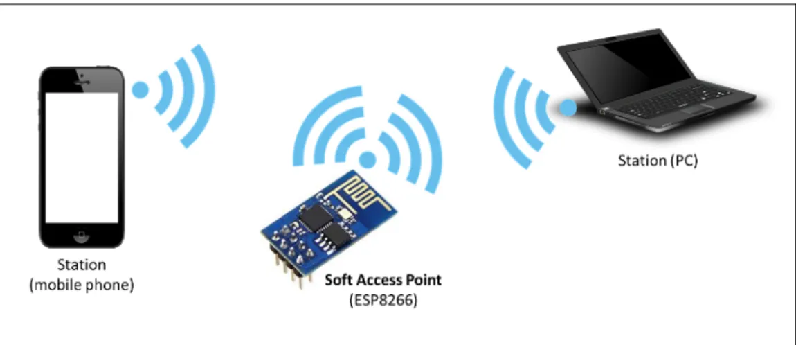
Who is Who
Devices that connect to Wi-Fi network are called stations (STA). Connection to Wi-Fi is provided by an access point (AP), that acts as a hub for one or more stations. The access point on the other end is connected to a wired network. An access point is usually integrated with a router to provide access from Wi-Fi network to the internet. Each access point is recognized by a SSID (Service Set IDentifier), that essentially is the name of network you select when connecting a device (station) to the Wi-Fi.
ESP8266 module can operate as a station, so we can connect it to the Wi-Fi network. It can also operate as a soft access point (soft-AP), to establish its own Wi-Fi network. Therefore we can connect other stations to such ESP module. ESP8266 is also able to operate both in station and soft access point mode. This provides possibility of building e.g.mesh networks.
Fig. 5.2: alt text
TheESP8266WiFilibrary provides wide collection of C++methods(functions) andpropertiesto configure and operate an ESP8266 module in station and / or soft access point mode. They are described in the following chapters.
Class Description
The ESP8266WiFilibrary is broken up into several classes. In most of cases, when writing the code, user is not concerned with this classification. We are using it to break up description of this library into more manageable pieces.
Fig. 5.3: alt text
Chapters below describe all function calls (methods and properties in C++ terms) listed in particular classes of ESP8266WiFi. Description is illustrated with application examples and code snippets to show how to use functions in practice. Most of this information is broken up into separate documents. Please follow to access them.
Station
Station (STA) mode is used to get ESP module connected to a Wi-Fi network established by an access point.
Fig. 5.4: alt text
ESP8266 Arduino Core Documentation, Release 2.4.0
Station class has several features to facilitate management of Wi-Fi connection. In case the connection is lost, ESP8266 will automatically reconnect to the last used access point, once it is again available. The same happens on module reboot. This is possible since ESP is saving credentials to last used access point in flash (non-volatile) memory. Using the saved data ESP will also reconnect if sketch has been changed but code does not alter the Wi-Fi mode or credentials.
Station Class documentation
Check out separate section with examples.
Soft Access Point
Anaccess point (AP)is a device that provides access to Wi-Fi network to other devices (stations) and connects them further to a wired network. ESP8266 can provide similar functionality except it does not have interface to a wired network. Such mode of operation is called soft access point (soft-AP). The maximum number of stations connected to the soft-AP is five.
Fig. 5.5: alt text
The soft-AP mode is often used and an intermediate step before connecting ESP to a Wi-Fi in a station mode. This is when SSID and password to such network is not known upfront. ESP first boots in soft-AP mode, so we can connect to it using a laptop or a mobile phone. Then we are able to provide credentials to the target network. Once done ESP is switched to the station mode and can connect to the target Wi-Fi.
Another handy application of soft-AP mode is to set upmesh networks. ESP can operate in both soft-AP and Station mode so it can act as a node of a mesh network.
Soft Access Point Class documentation Check out separate section with examples.
Scan
To connect a mobile phone to a hot spot, you typically open Wi-Fi settings app, list available networks and pick the hot spot you need. Then enter a password (or not) and you are in. You can do the same with ESP. Functionality of scanning for, and listing of available networks in range is implemented by the Scan Class.
Scan Class documentation.
Check out separate section with examples.
Client
The Client class createsclientsthat can access services provided byserversin order to send, receive and process data.
Fig. 5.6: alt text
Check out separate section with examples / list of functions
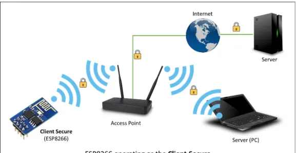
Client Secure
The Client Secure is an extension ofClient Classwhere connection and data exchange with servers is done using a secure protocol. It supportsTLS 1.1. TheTLS 1.2is not supported.
Secure applications have additional memory (and processing) overhead due to the need to run cryptography algorithms. The stronger the certificate’s key, the more overhead is needed. In practice it is not possible to run more than a single secure client at a time. The problem concerns RAM memory we can not add, the flash memory size is usually not the issue. If you like to learn howclient secure libraryhas been developed, access to what servers have been tested, and how memory limitations have been overcame, read fascinating issue report#43.
Check out separate section with examples / list of functions
Server
The Server Class createsserversthat provide functionality to other programs or devices, calledclients. Clients connect to sever to send and receive data and access provided functionality.
Check out separate section with examples / list of functions.
ESP8266 Arduino Core Documentation, Release 2.4.0
Fig. 5.7: alt text
Fig. 5.8: alt text
UDP
The UDP Class enables theUser Datagram Protocol (UDP)messages to be sent and received. The UDP uses a simple “fire and forget” transmission model with no guarantee of delivery, ordering, or duplicate protection. UDP provides checksums for data integrity, and port numbers for addressing different functions at the source and destination of the datagram.
Check out separate section with examples / list of functions.
Generic
There are several functions offered by ESP8266’sSDKand not present in Arduino WiFi library. If such function does not fit into one of classes discussed above, it will likely be in Generic Class. Among them is handler to manage Wi-Fi events like connection, disconnection or obtaining an IP, Wi-Fi mode changes, functions to manage module sleep mode, hostname to an IP address resolution, etc.
Check out separate section with examples / list of functions.
Diagnostics
There are several techniques available to diagnose and troubleshoot issues with getting connected to Wi-Fi and keeping connection alive.
Check Return Codes
Almost each function described in chapters above returns some diagnostic information.
Such diagnostic may be provided as a simple boolean type true' orfalse‘ to indicate operation result. You may check this result as described in examples, for instance:
Serial.printf("Wi-Fi mode set to WIFI_STA %s\n", WiFi.mode(WIFI_STA) ? "" : "Failed!
˓→");
Some functions provide more than just a binary status information. A good example is WiFi.status().
Serial.printf("Connection status: %d\n", WiFi.status());
This function returns following codes to describe what is going on with Wi-Fi connection: * 0 : WL_IDLE_STATUS when Wi-Fi is in process of changing between statuses * 1 : WL_NO_SSID_AVAILin case configured SSID cannot be reached * 3 : WL_CONNECTED after successful connection is established * 4 : WL_CONNECT_FAILED if password is incorrect * 6 : WL_DISCONNECTED if module is not configured in station mode
It is a good practice to display and check information returned by functions. Application development and trou-bleshooting will be easier with that.
Use printDiag
There is a specific function available to print out key Wi-Fi diagnostic information:
WiFi.printDiag(Serial);
A sample output of this function looks as follows:
ESP8266 Arduino Core Documentation, Release 2.4.0 Mode: STA+AP PHY mode: N Channel: 11 AP id: 0 Status: 5 Auto connect: 1 SSID (10): sensor-net Passphrase (12): 123!$#0&*esP BSSID set: 0
Use this function to provide snapshot of Wi-Fi status in these parts of application code, that you suspect may be failing.
Enable Wi-Fi Diagnostic
By default the diagnostic output from Wi-Fi libraries is disabled when you call Serial.begin. To enable de-bug output again, call Serial.setDede-bugOutput(true). To redirect dede-bug output to Serial1 instead, call Serial1.setDebugOutput(true). For additional details regarding diagnostics using serial ports please refer tothe documentation.
Below is an example of output for sample sketch discussed in Quick Start above with Serial. setDebugOutput(true): Connectingscandone state: 0 -> 2 (b0) state: 2 -> 3 (0) state: 3 -> 5 (10) add 0 aid 1 cnt
connected with sensor-net, channel 6 dhcp client start...
chg_B1:-40
...ip:192.168.1.10,mask:255.255.255.0,gw:192.168.1.9 .
Connected, IP address: 192.168.1.10
The same sketch without Serial.setDebugOutput(true) will print out only the following:
Connecting....
Connected, IP address: 192.168.1.10
Enable Debugging in IDE
Arduino IDE provides convenient method toenable debuggingfor specific libraries.
What’s Inside?
If you like to analyze in detail what is inside of the ESP8266WiFi library, go directly to theESP8266WiFifolder of esp8266 / Arduino repository on the GitHub.
To make the analysis easier, rather than looking into individual header or source files, use one of free tools to automat-ically generate documentation. The class index in chapter Class Description above has been prepared in no time using greatDoxygen, that is the de facto standard tool for generating documentation from annotated C++ sources.
Fig. 5.9: alt text
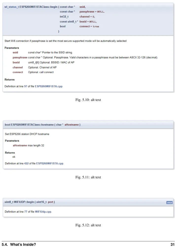
The tool crawls through all header and source files collecting information from formatted comment blocks. If devel-oper of particular class annotated the code, you will see it like in examples below.
If code is not annotated, you will still see the function prototype including types of arguments, and can use provided links to jump straight to the source code to check it out on your own. Doxygen provides really excellent navigation between members of library.
Several classes ofESP8266WiFiare not annotated. When preparing this document,Doxygenhas been tremendous help to quickly navigate through almost 30 files that make this library.
ESP8266 Arduino Core Documentation, Release 2.4.0
Fig. 5.10: alt text
Fig. 5.11: alt text
Fig. 5.12: alt text
CHAPTER
6
OTA Updates
Introduction
OTA (Over the Air) update is the process of loading the firmware to ESP module using Wi-Fi connection rather than a serial port. Such functionality became extremely useful in case of limited or no physical access to the module. OTA may be done using:
• Arduino IDE
• Web Browser
• HTTP Server
Arduino IDE option is intended primarily for software development phase. The two other options would be more useful after deployment, to provide module with application updates manually with a web browser, or automatically using a http server.
In any case, the first firmware upload has to be done over a serial port. If the OTA routines are correctly implemented in a sketch, then all subsequent uploads may be done over the air.
There is no imposed security on OTA process from being hacked. It is up to developer to ensure that updates are allowed only from legitimate / trusted sources. Once the update is complete, the module restarts, and the new code is executed. The developer should ensure that the application running on the module is shut down and restarted in a safe manner. Chapters below provide additional information regarding security and safety of OTA process.
Security
Module has to be exposed wirelessly to get it updated with a new sketch. That poses chances of module being violently hacked and loaded with some other code. To reduce likelihood of being hacked consider protecting your uploads with a password, selecting certain OTA port, etc.
Check functionality provided withArduinoOTAlibrary that may improve security:
void setPort(uint16_t port);
void setHostname(const char* hostname); void setPassword(const char* password);
Certain protection functionality is already built in and do not require any additional coding by developer.ArduinoOTA and espota.py useDigest-MD5to authenticate upload. Integrity of transferred data is verified on ESP side usingMD5 checksum.
Make your own risk analysis and depending on application decide what library functions to implement. If required, consider implementation of other means of protection from being hacked, e.g. exposing module for uploads only according to specific schedule, trigger OTA only be user pressing dedicated “Update” button wired to ESP, etc.
Safety
OTA process takes ESP’s resources and bandwidth during upload. Then module is restarted and a new sketch executed. Analyse and test how it affects functionality of existing and new sketch.
If ESP is placed in remote location and controlling some equipment, you should put additional attention what happens if operation of this equipment is suddenly interrupted by update process. Therefore, decide how to put this equipment into safe state before starting the update. For instance, your module may be controlling a garden watering system in a sequence. If this sequence is not properly shut down and a water valve left open, your garden may be flooded. The following functions are provided withArduinoOTAlibrary and intended to handle functionality of your applica-tion during specific stages of OTA, or on an OTA error:
void onStart(OTA_CALLBACK(fn)); void onEnd(OTA_CALLBACK(fn));
void onProgress(OTA_CALLBACK_PROGRESS(fn)); void onError(OTA_CALLBACK_ERROR (fn));
Basic Requirements
Flash chip size should be able to hold the old sketch (currently running) and the new sketch (OTA) at the same time. Keep in mind that the File system and EEPROM for example needs space too (one time) see flash layout.
ESP.getFreeSketchSpace();
can be used for checking the free space for the new sketch.
For overview of memory layout, where new sketch is stored and how it is copied during OTA process, see Update process - memory view.
The following chapters provide more details and specific methods of doing OTA.
Arduino IDE
Uploading modules wirelessly from Arduino IDE is intended for the following typical scenarios: - during firmware development as a quicker alternative to loading over a serial, - for updating small quantity of modules, - only if modules are available on the same network as the computer with Arduino IDE.
ESP8266 Arduino Core Documentation, Release 2.4.0
Requirements
• The ESP and the computer must be connected to the same network.
Application Example
Instructions below show configuration of OTA on NodeMCU 1.0 (ESP-12E Module) board. You can use any other board assuming that it meetsrequirementsdescribed above. This instruction is valid for all operating systems sup-ported by Arduino IDE. Screen captures have been made on Windows 7 and you may see small differences (like name of serial port), if you are using Linux and MacOS.
1. Before you begin, please make sure that you have the following s/w installed: • Arduino IDE 1.6.7 or newer -https://www.arduino.cc/en/Main/Software
• esp8266/Arduino platform package 2.0.0 or newer - for instructions followhttps://github.com/esp8266/ Arduino#installing-with-boards-manager
• Python 2.7 (do not install Python 3.5 that is not supported) -https://www.python.org/
Note: Windows users should select “Add python.exe to Path” (see below – this option is not selected by default).
2. Now prepare the sketch and configuration for the upload over a serial port.
• Start Arduino IDE and load sketch BasicOTA.ino available under File > Examples > ArduinoOTA
• Update SSID and password in the sketch, so the module can join your Wi-Fi network
• Configure upload parameters as below (you may need to adjust configuration if you are using a different
module):
Note: Depending on version of platform package and board you have, you may see Upload Using: in the menu above. This option is inactive and it does not matter what you select. It has been left for compatibility with older implementation of OTA and finally removed in platform package version 2.2.0. 3. Upload the sketch (Ctrl+U). Once done, open Serial Monitor (Ctrl+Shift+M) and check if module has joined
your Wi-Fi network:
Note: ESP module should be reset after serial upload. Otherwise subsequent steps will not work. Reset may be done automatically for you after opening serial monitor as visible on the screenshot above. It depends on how you have DTR and RTS wired from USB-Serial converter to the ESP. If reset is not done automatically, then do it by pressing reset button or manually cycling the power. For more details why this should be done please refer to FAQ regarding ESP.restart().
4. Only if module is connected to network, after a couple of seconds, the esp8266-ota port will show up in Arduino IDE. Select port with IP address shown in the Serial Monitor window in previous step:
Note: If OTA port does not show up, exit Arduino IDE, open it again and check if port is there. If it does not help, check your firewall and router settings. OTA port is advertised using mDNS service. To check if port is visible by your PC, you can use application like Bonjour Browser.
5. Now get ready for your first OTA upload by selecting the OTA port:
ESP8266 Arduino Core Documentation, Release 2.4.0
Note: The menu entry Upload Speed: does not matter at this point as it concerns the serial port. Just left it unchanged.
6. If you have successfully completed all the above steps, you can upload (Ctrl+U) the same (or any other) sketch over OTA:
Note: To be able to upload your sketch over and over again using OTA, you need to embed OTA routines inside. Please use BasicOTA.ino as an example.
Password Protection
Protecting your OTA uploads with password is really straightforward. All you need to do, is to include the following statement in your code:
ArduinoOTA.setPassword((const char *)"123");
Where 123 is a sample password that you should replace with your own.
Before implementing it in your sketch, it is a good idea to check how it works using BasicOTA.ino sketch available under File > Examples > ArduinoOTA. Go ahead, open BasicOTA.ino, uncomment the above statement that is already there, and upload the sketch. To make troubleshooting easier, do not modify example sketch besides what is absolutely required. This is including original simple 123 OTA password. Then attempt to upload sketch again (using OTA). After compilation is complete, once upload is about to begin, you should see prompt for password as follows: Enter the password and upload should be initiated as usual with the only difference being Authenticating...OK message visible in upload log.
You will not be prompted for a reentering the same password next time. Arduino IDE will remember it for you. You will see prompt for password only after reopening IDE, or if you change it in your sketch, upload the sketch and then try to upload it again.
Please note, it is possible to reveal password entered previously in Arduino IDE, if IDE has not been closed since last upload. This can be done by enabling Show verbose output during: upload in File > Preferences and attempting to upload the module.
The picture above shows that the password is visible in log, as it is passed to espota.py upload script. Another example below shows situation when password is changed between uploads.
When uploading, Arduino IDE used previously entered password, so the upload failed and that has been clearly reported by IDE. Only then IDE prompted for a new password. That was entered correctly and second attempt to upload has been successful.
ESP8266 Arduino Core Documentation, Release 2.4.0
Troubleshooting
If OTA update fails, first step is to check for error messages that may be shown in upload window of Arduino IDE. If this is not providing any useful hints, try to upload again while checking what is shown by ESP on serial port. Serial Monitor from IDE will not be useful in that case. When attempting to open it, you will likely see the following:
This window is for Arduino Yún and not yet implemented for esp8266/Arduino. It shows up because IDE is attempting to open Serial Monitor using network port you have selected for OTA upload.
Instead you need an external serial monitor. If you are a Windows user check outTermite. This is handy, slick and simple RS232 terminal that does not impose RTS or DTR flow control. Such flow control may cause issues if you are using respective lines to toggle GPIO0 and RESET pins on ESP for upload.
Select COM port and baud rate on external terminal program as if you were using Arduino Serial Monitor. Please see typical settings forTermitebelow:
Then run OTA from IDE and look what is displayed on terminal. Successful ArduinoOTA process using BasicOTA.ino sketch looks like below (IP address depends on your network configuration):
If upload fails you will likely see errors caught by the uploader, exception and the stack trace, or both. Instead of the log as on the above screen you may see the following:
If this is the case, then most likely ESP module has not been reset after initial upload using serial port.
The most common causes of OTA failure are as follows: * not enough physical memory on the chip (e.g. ESP01 with 512K flash memory is not enough for OTA), * too much memory declared for SPIFFS so new sketch will not fit between existing sketch and SPIFFS – see Update process - memory view, * too little memory declared in Arduino IDE for your selected board (i.e. less than physical size), * not resetting the ESP module after initial upload using serial port.
ESP8266 Arduino Core Documentation, Release 2.4.0
For more details regarding flash memory layout please checkFile system. For overview where new sketch is stored, how it is copied and how memory is organized for the purpose of OTA see Update process - memory view.
Web Browser
Updates described in this chapter are done with a web browser that can be useful in the following typical scenarios: • after application deployment if loading directly from Arduino IDE is inconvenient or not possible,
• after deployment if user is unable to expose module for OTA from external update server,
• to provide updates after deployment to small quantity of modules when setting an update server is not practica-ble.
Requirements
• The ESP and the computer must be connected to the same network.
Implementation Overview
Updates with a web browser are implemented using ESP8266HTTPUpdateServer class together with ESP8266WebServerand ESP8266mDNS classes. The following code is required to get it work:
setup()
MDNS.begin(host);
httpUpdater.setup(&httpServer); httpServer.begin();
MDNS.addService("http", "tcp", 80);
loop()
httpServer.handleClient();
Application Example
The sample implementation provided below has been done using:
• example sketch WebUpdater.ino available in ESP8266HTTPUpdateServer library, • NodeMCU 1.0 (ESP-12E Module).
You can use another module if it meets previously describedrequirements.
1. Before you begin, please make sure that you have the following software installed:
• Arduino IDE and 2.0.0-rc1 (of Nov 17, 2015) version of platform package as described underhttps:// github.com/esp8266/Arduino#installing-with-boards-manager
• Host software depending on O/S you use: (a) Avahihttp://avahi.org/for Linux
(b) Bonjourhttp://www.apple.com/support/bonjour/for Windows
ESP8266 Arduino Core Documentation, Release 2.4.0
(c) Mac OSX and iOS - support is already built in / no any extra s/w is required 2. Prepare the sketch and configuration for initial upload with a serial port.
• Start Arduino IDE and load sketch WebUpdater.ino available under File > Examples > ESP8266HTTPUpdateServer.
• Update SSID and password in the sketch, so the module can join your Wi-Fi network.
• Open File > Preferences, look for “Show verbose output during:” and check out “compilation” option.
Note: This setting will be required in step 5 below. You can uncheck this setting afterwards.
3. Upload sketch (Ctrl+U). Once done, open Serial Monitor (Ctrl+Shift+M) and check if you see the following message displayed, that contains url for OTA update.
Note: Such message will be shown only after module successfully joins network and is ready for an OTA upload. Please remember about resetting the module once after serial upload as discussed in chapterArduino IDE, step 3.
4. Now open web browser and enter the url provided on Serial Monitor, i.e. http://esp8266-webupdate. local/update. Once entered, browser should display a form like below that has been served by your module. The form invites you to choose a file for update.
Note: If entering http://esp8266-webupdate.local/update does not work, try replacing esp8266-webupdate with module’s IP address. For example, if your module IP is 192.168.1.100 then url should be http://192.168.1.100/update. This workaround is useful in case the host software installed in step 1 does not work. If still nothing works and there are no clues on the Serial Monitor, try to diagnose issue by opening provided url in Google Chrome, pressing F12 and checking contents of “Console” and “Network” tabs. Chrome provides some advanced logging on these tabs.
5. To obtain the file, navigate to directory used by Arduino IDE to store results of compilation. You can check the path to this file in compilation log shown in IDE debug window as marked below.
6. Now press “Choose File” in web browser, go to directory identified in step 5 above, find the file “WebUp-dater.cpp.bin” and upload it. If upload is successful, you will see “OK” on web browser like below.
Module will reboot that should be visible on Serial Monitor:
ESP8266 Arduino Core Documentation, Release 2.4.0
Just after reboot you should see exactly the same message HTTPUpdateServer ready! Open http:// esp8266-webupdate.local /update in your browser like in step 3. This is because module has been loaded again with the same code – first using serial port, and then using OTA.
Once you are comfortable with this procedure, go ahead and modify WebUpdater.ino sketch to print some additional messages, compile it, locate new binary file and upload it using web browser to see entered changes on a Serial Monitor.
You can also add OTA routines to your own sketch following guidelines inImplementation Overviewabove. If this is done correctly, you should be always able to upload new sketch over the previous one using a web browser.
In case OTA update fails dead after entering modifications in your sketch, you can always recover module by loading it over a serial port. Then diagnose the issue with sketch using Serial Monitor. Once the issue is fixed try OTA again.
HTTP Server
ESPhttpUpdateclass can check for updates and download a binary file from HTTP web server. It is possible to download updates from every IP or domain address on the network or Internet.
Requirements
• web server
Arduino code
Simple updaterSimple updater downloads the file every time the function is called.
ESPhttpUpdate.update("192.168.0.2", 80, "/arduino.bin");
Advanced updater
Its possible to point update function to a script at the server. If version string argument is given, it will be sent to the server. Server side script can use this to check if update should be performed.
Server side script can respond as follows: - response code 200, and send the firmware image, - or response code 304 to notify ESP that no update is required.
t_httpUpdate_return ret = ESPhttpUpdate.update("192.168.0.2", 80, "/esp/update/
˓→arduino.php", "optional current version string here");
switch(ret) {
case HTTP_UPDATE_FAILED:
Serial.println("[update] Update failed.");
break;
case HTTP_UPDATE_NO_UPDATES:
Serial.println("[update] Update no Update.");
break;
case HTTP_UPDATE_OK:
Serial.println("[update] Update ok."); // may not called we reboot the ESP
break; }
Server request handling
Simple updaterFor the simple updater the server only needs to deliver the binary file for update.
Advanced updater
For advanced update management a script needs to run at the server side, for example a PHP script. At every update request the ESP sends some information in HTTP headers to the server.
Example header data:
[HTTP_USER_AGENT] => ESP8266-http-Update [HTTP_X_ESP8266_STA_MAC] => 18:FE:AA:AA:AA:AA [HTTP_X_ESP8266_AP_MAC] => 1A:FE:AA:AA:AA:AA [HTTP_X_ESP8266_FREE_SPACE] => 671744 [HTTP_X_ESP8266_SKETCH_SIZE] => 373940 [HTTP_X_ESP8266_SKETCH_MD5] => a56f8ef78a0bebd812f62067daf1408a [HTTP_X_ESP8266_CHIP_SIZE] => 4194304 [HTTP_X_ESP8266_SDK_VERSION] => 1.3.0
[HTTP_X_ESP8266_VERSION] => DOOR-7-g14f53a19
With this information the script now can check if an update is needed. It is also possible to deliver different binaries based on the MAC address for example.
Script example:
<?PHP
header('Content-type: text/plain; charset=utf8', true);
function check_header($name, $value = false) { if(!isset($_SERVER[$name])) {
return false; }
if($value && $_SERVER[$name] != $value) { return false;
}
return true; }
function sendFile($path) {
header($_SERVER["SERVER_PROTOCOL"].' 200 OK', true, 200); header('Content-Type: application/octet-stream', true);
header('Content-Disposition: attachment; filename='.basename($path)); header('Content-Length: '.filesize($path), true);
header('x-MD5: '.md5_file($path), true); readfile($path);
}
if(!check_header('HTTP_USER_AGENT', 'ESP8266-http-Update')) {
header($_SERVER["SERVER_PROTOCOL"].' 403 Forbidden', true, 403); echo "only for ESP8266 updater!\n";
exit(); }
ESP8266 Arduino Core Documentation, Release 2.4.0 if( !check_header('HTTP_X_ESP8266_STA_MAC') || !check_header('HTTP_X_ESP8266_AP_MAC') || !check_header('HTTP_X_ESP8266_FREE_SPACE') || !check_header('HTTP_X_ESP8266_SKETCH_SIZE') || !check_header('HTTP_X_ESP8266_SKETCH_MD5') || !check_header('HTTP_X_ESP8266_CHIP_SIZE') || !check_header('HTTP_X_ESP8266_SDK_VERSION') ) {
header($_SERVER["SERVER_PROTOCOL"].' 403 Forbidden', true, 403); echo "only for ESP8266 updater! (header)\n";
exit(); } $db = array( "18:FE:AA:AA:AA:AA" => "DOOR-7-g14f53a19", "18:FE:AA:AA:AA:BB" => "TEMP-1.0.0" ); if(!isset($db[$_SERVER['HTTP_X_ESP8266_STA_MAC']])) {
header($_SERVER["SERVER_PROTOCOL"].' 500 ESP MAC not configured for updates',
˓→true, 500);
}
$localBinary = "./bin/".$db[$_SERVER['HTTP_X_ESP8266_STA_MAC']].".bin";
// Check if version has been set and does not match, if not, check if // MD5 hash between local binary and ESP8266 binary do not match if not. // then no update has been found.
if((!check_header('HTTP_X_ESP8266_SDK_VERSION') && $db[$_SERVER['HTTP_X_ESP8266_STA_
˓→MAC']] != $_SERVER['HTTP_X_ESP8266_VERSION'])
|| $_SERVER["HTTP_X_ESP8266_SKETCH_MD5"] != md5_file($localBinary)) { sendFile($localBinary);
} else {
header($_SERVER["SERVER_PROTOCOL"].' 304 Not Modified', true, 304); }
header($_SERVER["SERVER_PROTOCOL"].' 500 no version for ESP MAC', true, 500);
Stream Interface
TODO describe Stream Interface
The Stream Interface is the base for all other update modes like OTA, http Server / client.
Updater class
Updater is in the Core and deals with writing the firmware to the flash, checking its integrity and telling the bootloader to load the new firmware on the next boot.
Update process - memory view
• The new sketch will be stored in the space between the old sketch and the spiff. • on the next reboot the “eboot” bootloader check for commands.
• the new sketch is now copied “over” the old one. • the new sketch is started.
CHAPTER
7
Boards
Adafruit HUZZAH ESP8266 (ESP-12)
TODO: add notes
ESPresso Lite 1.0
ESPresso Lite 1.0 (beta version) is an Arduino-compatible Wi-Fi development board powered by Espressif System’s own ESP8266 WROOM-02 module. It has breadboard-friendly breakout pins with in-built LED, two reset/flash buttons and a user programmable button . The operating voltage is 3.3VDC, regulated with 800mA maximum current. Special distinctive features include on-board I2C pads that allow direct connection to OLED LCD and sensor boards.
ESPresso Lite 2.0
ESPresso Lite 2.0 is an Arduino-compatible Wi-Fi development board based on an earlier V1 (beta version). Re-designed together with Cytron Technologies, the newly-revised ESPresso Lite V2.0 features the auto-load/auto-program function, eliminating the previous need to reset the board manually before flashing a new auto-load/auto-program. It also feature two user programmable side buttons and a reset button. The special distinctive features of on-board pads for I2C sensor and actuator is retained.
Phoenix 1.0
Product page:http://www.espert.co