HAL Id: inria-00525791
https://hal.inria.fr/inria-00525791
Submitted on 12 Oct 2010
HAL is a multi-disciplinary open access
archive for the deposit and dissemination of
sci-entific research documents, whether they are
pub-lished or not. The documents may come from
teaching and research institutions in France or
abroad, or from public or private research centers.
L’archive ouverte pluridisciplinaire HAL, est
destinée au dépôt et à la diffusion de documents
scientifiques de niveau recherche, publiés ou non,
émanant des établissements d’enseignement et de
recherche français ou étrangers, des laboratoires
publics ou privés.
Using SysML for Smart Surface Modeling
Alain Giorgetti, Ahmed Hammad, Bruno Tatibouët
To cite this version:
Alain Giorgetti, Ahmed Hammad, Bruno Tatibouët. Using SysML for Smart Surface Modeling.
dMEMS’10, 1st workshop on design, control and software implementation for distributed MEMS, Jun
2010, Besançon, France. pp.100–107. �inria-00525791�
Using SysML for Smart Surface Modeling
Alain Giorgetti, Ahmed Hammad and Bruno Tatibou¨et LIFC
University of Franche-Comt´e 16, Route de Gray, F-25030 Besanc¸on
{alain.giorgetti, ahmed.hammad, bruno.tatibouet}@univ-fcomte.fr
Abstract—A smart surface is a distributed Micro-Electro-Mechanical System (MEMS) designed for conveying micro-scopic objects over a meso-scale distance, by the coordinated action of several microcells composed of microsensors, microac-tuators and control units. We present a high-level description of a smart surface with the System Modeling Language (SysML). We show how various SysML views (requirement, block, constraint and parametric diagrams) may accompany the design of such a complex system with precise but simple models. We also establish links between SysML and other technologies and tools for complex system modeling.
Keywords-Smart Surface, SysML, Modeling
I. INTRODUCTION
Current miniaturization and integration trends of elec-tronic devices require to assemble chips and other compo-nents that become too small to be directly handled by hu-mans. The future electronics assembly industry will have to scale with the technology, using automated micromachines combining manipulators and intelligent conveying systems. A smart surface is a distributed Micro-Electro-Mechanical System (MEMS) designed to convey microscopic objects over a meso-scale distance. The global conveyance effect results from the coordinated action of microcells spatially organized in a 2D array. Each microcell is composed of a microsensor, a microactuator and a control unit. The control units realize communications with their neighbours and computations to adjust the actuator local effects from the sensor measures.
Modeling such a complex system is a challenge addressed in [1], [2], [3] with the motivation of validating by simulation the realization of a Distributed MEMS Air-flow Surface Micromanipulator (DMASM, see Figure 1). For technolog-ical reasons, the corresponding realization was limited to the microactuator layer. Integrating the sensor and control layers was the goal of a multidisciplinary research project named “Smart Surface”, initiated in 2007 and supported by the French Research Agency (ANR).
During this project many attempts have failed to extend the existing models with the distributed control of the microactuators. We claim that the failure is due in some extend to the intrication of the model itself, but also to the modeling language, namely VDHL-AMS [4]. The usual practice of this extension of VHDL to mixed signals was
Figure 1. Conveyance of micro objects
indeed not shared by the physicians, automaticians and com-puter scientists collaborating in the project. Anticipating this difficulty we have contributed to this project by investigating an adapted language.
A previous work [5] considered a smart surface as a set of heterogenous SoC (System on Chip) systems. System on Chip (SoC) refers to integrating all components of an electronic system into a single integrated electronic circuit. It may contain digital, analog, mixed-signal, and often radio-frequency functions all on one chip. A typical application is in the area of embedded systems. The interaction and inte-gration of hardware and software components are essential parts of their design. A preliminary smart surface modeling was realized in [5] with the UML4Soc profile.
The present work suggests to use the System Modeling Language (SysML) as a better solution for the multidis-ciplinary modeling of relevant physics (electromechanics, electronics, . . . ) and control of distributed MEMS. SysML is a modeling language for systems engineering. This covers complex systems which include a broad range of heteroge-neous domains, in particular hardware and software. Several similarities exist between the methods used in the area of systems engineering and complex SoC design, such as the need for accurate requirements capture, system specification and simulation, system validation and verification. There are several work [6], [7], [5] in this area, using UML as specification language and checking the properties of
reliability.
This paper addresses the graphical description of a smart surface by SysML diagrams. These diagrams help under-standing the specification for stakeholders who are not familiar with the VHDL-AMS language, such as customers or certification authorities. SysML facilitates also communi-cation between project members.
Section II gives a brief description of SysML. Section III informally presents the smart surface example. Section IV presents its modeling by various diagrams, including the requirement diagram, two block diagrams and the parametric diagram. Finally, we end up by a conclusion and some perspectives of this work.
II. SysML
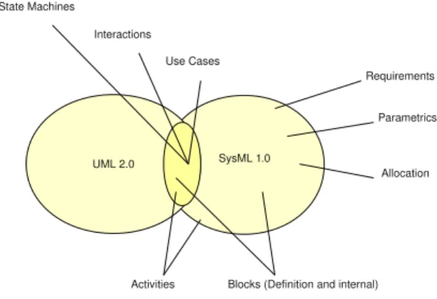
SysML has been proposed by the Object Manage-ment Group (OMG, http://www.omg.org) together with the International Council on Systems Engineering (IN-COSE, http://www.incose.org) and the AP233 consor-tium (http://ap233.eurostep.com) with the aim to define a general purpose modeling language for systems en-gineering. It is based on the actual standard for soft-ware engineering, the Unified Modeling Language (UML, http://www.uml.org) version 2.0, with some extensions (see figure 2), and it was developed as a response to the request for proposal (RFP) issued by the OMG in March 2003 (http://syseng.omg.org/UML for SE RFP.htm) and adopted as a standard in May 2006 (http://www.omgsysml.org). SysML is a modeling language for representing systems and product architectures, as well as their behavior and structure. It adapts to systems engineering standard modeling techniques from software development, and supports the specification, design, analysis, verification and validation of a broad range of complex systems.
Figure 2. Comparison of SysML 1.0 with UML 2.0
(SysML) is the first formal UML profile dedicated to the specification of professional engineering systems. It has been developed during many years but has only recently
been fully agreed and standardized. SysML has meanwhile evolved over several major iterations, including two sep-arated proposals from different teams. As a consequence of this long and often confusing evolution, there are many misconceptions associated with SysML, such as its status as a profile, its autonomy as a language and how it can be applied in a better way for systems engineering. SysML significantly extends UML with system-related formal constructs, such as real-world physical constraints, physical flows and connec-tions between physical components.
III. Smart Surface INFORMALDESCRIPTION A smart surface consists of a rectangular grid of rectangu-lar cells. Each cell consists of a microactuator, a microsensor and a microcontroller. The purpose of a smart surface is to sort microscopic objects according to parameters such as their shape and/or colour. The following smart surface characteristics are extracted from a specification document conjointly written during the “Smart Surface” project. A. The grid
• The grid is divided in 24 lines of 24 cells each, a cell
having a size of about 2 mm.
• There is no centralized control. Cells communicate step
by step through their direct neighbours. B. Objects to sort
• We assume, at first, that a object should be found from
a small number of options (2, 3 or 4).
• Objects to convey are typically included in a square of
less than 4 µm a side. C. Microactuator
• A microactuator can communicate with its 4 neighbours
via its cell controller,
• A microactuator acts on the objects through an air-flow
(should not be specified at this level). D. Sorting
• In the first instance, at a given moment, at most one
object may be present on the smart surface,
• The sorting will be done according to the shape of the
object.
IV. MODELING ASMARTSURFACE WITHSysML The former informal specification is obviously incom-plete. Even more detailed, it would remain imprecise, due to the ambiguities of natural languages. We suggest to replace it with SysML diagrams. Typical instances of the most important diagrams for a smart surface modeling are presented one after the other. Physical concepts and laws are borrowed from [2].
Figure 3. Requirement diagram
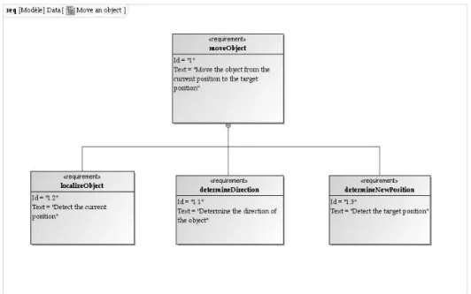
A. Requirement diagram
The SysML requirement diagram allows several ways to represent requirements relationships. The relationships derive, satisfy, verify, refine, trace and hierarchy are briefly explained below :
• The derive relationship relates a derived requirement
to its source requirement. In a requirement diagram, the derive relationship is represented by the keyword “deriveReqt”.
• The satisfy requirement describes how a model satisfies
one or more requirements. It represents a dependency relationship between a requirement and a model ele-ment (from another SysML diagram) that fulfills that requirement. This relationship is represented by the keyword “satisfy”. One example is to associate a re-quirement to a SysML block diagram.
• The verify relationship defines how a test case can
verify a requirement. This includes standard verification methods for inspection, analysis, demonstration or test. The keyword “verify” represents this relationship.
• The refine relationship describes how a model element
(or set of elements) can be used to later refine a requirement. For example, how a Use Case can rep-resent a requirement in a SysML requirement diagram. The relationship is represented in the diagram by the keyword “refine”.
• The trace relationship provides a general purpose
re-lationship between a requirement and any other model element. Its semantics has no real constraints and is not well-defined as the other relationships.
• In large and complex systems, it is common to have a
hierarchy of requirements, and their organization into various levels helps in dealing with system complexity. SysML allows splitting complex requirements into sim-pler ones, as a hierarchy of requirements related to each other. The advantage is that the complexity of systems is treated from the early beginning of development, by decomposing complex requirements.
In Figure 3, the requirements localizeObject, determineDi-rection and determineNewPosition are broken down from the requirement moveObject.
B. Block Definition Diagram
SysML provides a structural element called a block. A block can represent any type of component of the system, physical, logical, functional, or human. Blocks are declared within a Block Definition Diagram (BDD) based on the UML Composite Structure Diagram, which extends the UML Class Diagram. A BDD describes the structure of the system. In particular, it can represent association and composition relationships.
Figure 4 shows an example of a BDD with four blocks. It is the first level of modeling of the smart surface, the most abstract. The block named Smart Surface represents the system as a whole. It is decomposed into three sub blocks
Figure 5. Block Definition Diagram, level 2
(Surface, Interface and Object) and is linked to them by the following relationships :
• composition to the Surface and Interface blocks, • aggregation to the Object block.
The block named Object represents a microscopic object in the Smart Surface environment. The block named Surface represents the distributed MEMS under design. The block named Interface represents all the interactions between
Surface and Object.
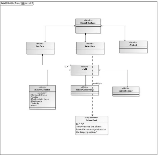
At a second (more detailed) level of modeling (see Figure 5), the block Surface is linked by composition to a new block named Cell. The composition relation with the block Cell is labeled with the multiplicity 1..∗ and expresses that the surface is composed of many cells. The block Cell is itself composed of three parts, namely a microactuator, a microsensor and a microcontroller. Each of them is represented by a block.
The two blocks Surface and Cell represent physical com-ponents and together constitute a physical model of the smart surface. On the other hand the block Interface is a logical model of the surface interactions with its environment, here reduced to a microscopic object moving above the surface. This concept of interface has been introduced in [2] to model the multiphysical exchanges (mechanical, electrical, fluidic, etc) between a MEMS and its environment.
Requirement traceability is made possible by the defini-tion of a reladefini-tionship satisfy between the Interface block and an element of the requirement diagram.
C. Internal Block Diagram
The Internal Block Diagram (IBD) allows the designer to refine the structural aspect of the model. The IBD is the equivalent in SysML of the composite structure diagram in UML. In the IBD, parts are basic elements assembled to
Figure 4. Block Definition Diagram, level 1
define how they collaborate to realize the block structure and/or behavior. In the IBD the designer can refine the definition of the interactions between blocks by defining flow ports along the following rules:
• ports are parts available for connection outside of the
owning block;
• ports are typed by interfaces or blocks which define
what can be exchanged through them;
• ports are connected using connectors which represent
the use of an association in the IBD. Two types of ports are available in SysML:
• standard ports handling requests and invocations of
services with other blocks (basically the same concept as in UML 2.0);
• flow ports which let blocks exchange flows of
informa-tion.
Flow ports specify the interaction points among blocks and parts supporting the integration of behavior and structure. For standard ports, an interface class is used to list the services offered by the block. For flow ports, a flow specifi-cation is created to list the type of data that can flow through the port.
Figure 6 shows how to represent the internal structure of the block Cell by an IBD.
Figure 6 shows two flow ports: the flow portDirection enable continuously passes the direction of the object. Through the flow port Object detection the microsensor sends to the microcontroller a signal to indicate the detection of an object.
D. Constraint Blocks
A constraint block encapsulates a physical property of the system or a constraint on it. Syntactically it is a block labeled with the keyword <<constraint>> and identified by a name. The next compartment in the constraint block defines
Figure 6. Internal Block Diagram of the cell block
the constraint as an arbitrarily complex logical expression, in a formal (e.g. using MathML (http://www.w3.org/Math) or OCL (http://www.omg.org/spec/OCL/2.0) or informal lan-guage. The last constraint block compartment enumerates the constraint parameters as attributes with their type.
Up to here, our smart surface modeling is generic. It does not yet describe the physical structure and behavior of a particular realization. Constraint blocks are the key for this physical description.
As a first example, Figure 7 shows constraint blocks specifying the behavioral laws of a pneumatic microactuator represented in Figure 1 and described in VHDL-AMS in [2]. The constraint block named Electrostatic force corresponds to the use case when the microactuator is active and produces an air flow in one direction. Two other constraints not reproduced here correspond to the other two cases, when the microactuator is active in the reverse direction and when it is off.
Constraint blocks define generic constraints that can be reused in multiple contexts. Reusable constraint definitions are specified in block definition diagrams and can be packaged into general-purpose or domain-specific model libraries. For instance the Velocity constraint in Figure 7 is a general-purpose definition that could be packaged and imported in the present model.
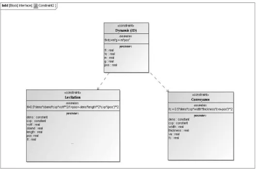
Along the functional virtual prototyping (FVP) method-ology promoted in [1], the constraint blocks presented in Figure 7 take part to a low physical description level called the “component model”. But constraint blocks can also de-scribe the highest global behavioral description level of FVP, called the “behavioral model”. Figure 8 illustrates this with three constraint blocks specifying the interations between the MEMS array and an object above it. It is a simplified version of the behavioral model described (mathematically and in VHDL-AMS) in [1]. Since it considers the smart surface as a whole, this specification is clearly at the most global modeling level and is a possible realization of the
Figure 7. Constraint blocks of a pneumatic microactuator
Figure 8. Constraint blocks of the interface
dy-namic and Vertical dydy-namic are two instances of the
fundamental law of solid mechanics, respectively expressed along an horizontal axis and the vertical z-axis. The hor-izontal axis can be assumed to be the x-axis, a simi-lar law not reproduced here also holds along the y-axis.
fl and fc respectively are the levitation and conveyance
forces produced by the air-flow, m is the object mass and (posx,posy,posz) is its position in a 3D Cartesian coordinate system. The Levitation and Conveyance constraint blocks define approximative laws to compute the intensity of the levitation and conveyance forces, respectively. The conveyed object is assumed to be parallelepipedic with a square side of length length and a thickness given by the thickness quantity. dens is the air density, cxp is the air pressure, voff (resp. va) is the air-flow velocity when the microactuator is off (resp. on).
Constraint blocks are linked by a dependency relationship expressing that changes in one model element (the supplier) impact another model element (the client). A dependency relationship can also represent precedence. For example the equation in the block Conveyance must be solved before that in the block Horizontal dynamic, hence the dependency relationship in Figure 8 between the two blocks.
E. Parametric Diagram
A Parametric Diagram (PD) is associated to a block and makes use of constraint blocks, defined in a Block Definition Diagram, as constrain properties for its owning block. It is a new diagram type specific to SysML. Syntactically a PD is similar to an IBD, with the restriction that connectors are either between two constraint parameters or between a constraint parameter and a parameter of the owning block.
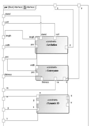
Figure 9 shows the PD of the block Interface, with connectors between the four constraint blocks from Figure 8. The parameters on the diagram edges are the concrete
Inter-face block attributes. Except the gravitational constant g the
interface attributes either come from the surface (voff, va) or from the conveyed object (mass m, shape characterized by
length and thickness, position defined by posx and posz).
Figure 10 is the PD of the microActuator block. Among others it shows how the mathematical formula which ex-presses the contact voltage (Vpull−in) is related to other constraints and quantities. This constraint requires five input parameters. lv is the length of vertical suspending beam,
keq is the spring stiffness, epsilon is the dielectric constant
of vacuum, h is the thickness of suspending beam, and
g0 is the initial gap between electrodes. These values may
either come from the external environment or from results of other equations. The Vpullin block also provides the output parameter vpullin.
V. CONCLUSION AND PERSPECTIVES
We have presented a hierarchical modeling of a smart surface with SysML. The first two levels are generic in the
Figure 9. Parametric diagram of the interface block
sense that they can be refined into any physical model of intelligent conveying surface. As an example of possible re-finement we have presented SysML diagrams corresponding to the distributed MEMS air-flow surface micromanipulator from [1].
As SysML is a language, not a methodology, it can be smoothly integrated in any existing design methodology and can thus significantly improve the development process of an organization. There is no need to do radical changes in the current methodology, which would involve too many risks. In addition SysML is a UML-based language, which is widely known and used, both in academia and industry. It can also facilitate communication between all professionals involved in a system design.
System modeling and simulation traditionally have been performed using quite different tools, e.g., relatively infor-mal graphical diagrams for system description, and forinfor-mal languages for simulation. The emergence of SysML may provide a way to create formal system models, and link them directly to formal simulation languages as Rosetta [8]. The potential for this approach is quite interesting, as it would permit users to develop system models that could
Figure 10. Parametric diagram of the microactuator block
be automatically parsed into specific analysis models. A perspective is to establish links between SysML and tools and technologies for modeling used to represent or describe complex systems. In the field of complex systems, engineers and researchers often use VHDL-AMS. We plan to create the following links between SysML and VHDL-AMS:
• Generating VHDL-AMS code from SysML diagrams • Extracting SysML diagrams from VHDL-AMS code • Extending the SysML metamodel with VHDL-AMS
characteristics.
ACKNOWLEDGMENT
This work is supported by the ANR-06-ROBO-0009-03 project Smart Surface.
REFERENCES
[1] Y.-A. Chapuis, L. Zhou, H. Fujita, and Y. Herv´e, “Multi-domain simulation using VHDL-AMS for distributed MEMS in functional environment: Case of a 2D air-jet micromanipu-lator,” Sensors and Actuators A: Physical, vol. 148, no. 1, pp. 224 – 238, 2008.
[2] L. Zhou, “Mod´elisation VHDL-AMS multi-domaines de struc-tures intelligentes, autonomes et distribu´ees `a base de MEMS,” Ph.D. dissertation, Institut d’Electronique du Solide et des Syst`emes, University of Strasbourg (France), 2007.
[3] L. Zhou, Y.-A. Chapuis, J.-P. Blond´e, H. Berviller, Y. Fukuta, and H. Fujita, “Integrated control strategy for autonomous decentralized conveyance systems based on distributed MEMS arrays,” in Proc. SPIE, Smart Structures and Materials 2004:
Modeling, Signal Processing, and Control, R. C. Smith, Ed.,
vol. 5383, March 2004, pp. 498–506.
[4] E. Christen and K. Bakalar, “VHDL-AMS-A Hardware Descrip-tion Language for Analog and Mixed-Signal ApplicaDescrip-tions,” in
IEEE Trans. Circuits & Systems-II, vol. 46, no. 10, Oct 1999,
pp. 1263–1272.
[5] A. Hammad, H. Mountassir, and B. Tatibouet, “Using the pro-file UML4SoC for modeling a smart surface,” in ICEEDT’08,
2nd int. conf. on Electrical Engineering Design and Technol-ogy, Nov. 2008, proceedings on CD-ROM. 6 pages.
[6] R. Malik and R. M¨uhlfeld, “A case study in verification of UML statecharts: the PROFIsafe protocol,” in Proc. 5th
Workshop on Tools for System Design and Verification, FM-TOOLS 2002, 2002, pp. 89–93.
[7] D. Drusinsky, Modeling and Verification using UML
State-charts. Elsevier, 2006.
[8] P. Alexander and C. Kong, “Rosetta: Semantic support for model-centered systems-level design,” IEEE Computer, vol. 34, no. 11, pp. 64–70, 2001.