Cutting the Cord in Virtual Reality
The MIT Faculty has made this article openly available.
Please share
how this access benefits you. Your story matters.
Citation
Abari, Omid, et al. "Cutting the Cord in Virtual Reality." HotNets '16
Proceedings of the 15th ACM Workshop on Hot Topics in Networks,
9-10 November, 2016, Atlanta, Georgia, ACM Press, 2016, pp. 162–
68.
As Published
http://dx.doi.org/10.1145/3005745.3005770
Publisher
Association for Computing Machinery
Version
Author's final manuscript
Citable link
http://hdl.handle.net/1721.1/114693
Terms of Use
Creative Commons Attribution-Noncommercial-Share Alike
Cutting the Cord in Virtual Reality
Omid Abari
Dinesh Bharadia
Austin Duffield
Dina Katabi
MIT CSAIL
{abari, dineshb, duffield, dina}@csail.mit.edu
ABSTRACT
Today’s virtual reality (VR) headsets require a cable connec-tion to a PC or game console. This cable significantly limits the player’s mobility and hence her VR experience. The high data rate requirement of this link (multiple Gbps) precludes its replacement by WiFi. In this paper, we focus on using mmWave technology to deliver multi Gbps wireless commu-nication between VR headsets and their game consoles. The challenge, however, is that mmWave signals can be easily blocked by the player’s hand or head motion. We describe a novel system design and algorithms that allow mmWave links to sustain high data rates even in the presence of block-age, enabling a high-quality untethered VR experience.
1.
INTRODUCTION
The past few years have witnessed major advances in aug-mented reality and virtual reality (VR) systems, which have led to accelerated market growth. Facebook has recently started shipping their VR headset (Oculus Rift) and expects to ship more than 2 million headsets by 2017 [4]. HTC sold more than 15,000 VR headsets in the first 10 minutes fol-lowing release [5]. These devices are expected to soon dom-inate the gaming and entertainment industry, and they have found applications in manufacturing and healthcare [12, 13]. However, a key challenge prevents this technology from achieving its full potential. High-quality VR systems need to stream multiple Gbps of data from a data source (PC or game console) to the headset. As a result, these headsets have an HDMI cable snaking down the player’s neck and hard-wiring her to the PC, as shown in Fig 1. The cable not only limits the player’s mobility and interferes with the VR ex-perience, but also creates a tripping hazard since the headset covers the player’s eyes. This has left the industry search-ing for untethered solutions that can deliver a high-quality Permission to make digital or hard copies of all or part of this work for personal or classroom use is granted without fee provided that copies are not made or distributed for profit or commercial advantage and that copies bear this notice and the full citation on the first page. Copyrights for components of this work owned by others than the author(s) must be honored. Abstracting with credit is permitted. To copy otherwise, or republish, to post on servers or to redistribute to lists, requires prior specific permission and/or a fee. Request permissions from [email protected].
HotNets-XV, November 09 - 10, 2016, Atlanta, GA, USA c
2016 Copyright held by the owner/author(s). Publication rights licensed to ACM. ISBN 978-1-4503-4661-0/16/11. . . $15.00
DOI:http://dx.doi.org/10.1145/3005745.3005770
Figure 1—Virtual Reality experience: The headset’s cable not only limits the player’s mobility, but also creates a tripping hazard. VR experience without these limitations. Unfortunately, typ-ical wireless systems such as WiFi cannot support the re-quired data rates. Moreover, the strict latency constraints on VR systems (about 10ms) preclude the use of compres-sion/decompression to accommodate lower data rates [21]. This challenge has led to awkward products: Zotac has gone as far as stuffing a full PC in the player’s backpack in the hope of delivering an untethered VR.
Ideally, one would like to replace the HDMI cable with a wireless link. In fact, multiple companies have advocated the use of mmWave for VR since mmWave has been specif-ically designed to deliver multi-Gbps data rates [8, 1]. The term mmWave refers to high-frequency RF signals: 24GHz and higher. The 802.11ad standard operates in mmWave and can transmit over 2GHz of bandwidth and deliver up to 6.8 Gbps. However, using mmWave links for the VR applica-tion presents some difficulty because such high frequency signals require a line-of-sight between transmitter and re-ceiver. They do not work well through obstacles or reflec-tions. Said differently, these links would work well when the receiver on the headset faces the transmitter and has a clear line of sight, but if the player turns her head to look around or if other people in the environment obstruct the receiver’s view to the transmitter, the signal will be lost (see Fig. 2). In fact, if the player moves her hand in front of the head-set, this motion will block the signal and cause a glitch in the data stream (shown in our empirical results in §3). This prob-lem is further complicated by the fact that mmWave antennas are highly directional and typically generate narrow beams. Hence, even a small obstacle like the player’s hand can block the signal. While temporary outages are common in wireless communication, the VR data is non-elastic: it cannot tolerate
any degradation in SNR and data rate.
One naïve solution to overcome this challenge is to deploy multiple mmWave transmitters in the room to guarantee that there is always a line of sight between the transmitter and the headset receiver. However, this defeats the purpose of a wireless design in the first place because it requires enor-mous cabling complexity, extending many HDMI cables in the environment to connect each transmitter to the PC. Fur-ther, requiring multiple full-fledged mmWave transceivers will significantly increase the cost of VR systems and limit their adoption in the consumer market.
We propose MoVR, a novel system for addressing the problem. MoVR is a configurable mmWave reflector. It has no transmit or receive capabilities (i.e., transmit or receive baseband chains). It acts as a programmable mirror that de-tects the direction of the incoming mmWave signal and re-configures itself to reflect it toward the receiver on the head-set. MoVR reflects the signal without loss of SNR –i.e., with-out reduction in data rate in comparison to the direct line of sight. Furthermore, in contrast to a traditional mirror, MoVR does not require the angle of reflection to be equal to the an-gle of incidence. Both anan-gles can be programmed so that our mirror can receive the signal from the mmWave transmitter at the data source and reflect it towards the player’s headset, regardless of its direction.
MoVR’s design overcomes multiple challenges. In par-ticular, though it has no transmit or receive chains, MoVR needs to detect the direction of the signal from the PC and the direction of the headset so that it can set angles of inci-dence and reflection appropriately. Recall that mmWave sig-nals are highly directional. Identifying the best signal direc-tion between two nodes typically requires them to transmit and receive, yet MoVR can neither transmit nor receive; it can only reflect signals. In §4, we present a novel protocol that measures the direction along which a signal propagates using the backscatter principle, which works correctly even when one node has no transmit or receive capabilities.
Another challenge in designing MoVR stems from the leakage between the transmit and receive antennas. At a high level, MoVR works by capturing the RF signal on its receive antenna, amplifying it, and reflecting it using a transmit an-tenna. However, some of the signal reflected by MoVR is also received by its own receive antenna. This means that the output of the amplifier is fed back to the input of the plifier. This creates a feedback loop that can cause the am-plifier to saturate, thereby generating garbage signals. While the same leakage problem appears in some prior technolo-gies working at lower frequencies, both the nature of the problem and the solution are different. For example, relays at lower frequencies cancel their own leakage but they require full transceiver chains for accurate estimation of the leakage and complex circuits to achieve this. Moreover, such systems have a fixed amount of leakage between the transmit and re-ceive antennas. In contrast, MoVR does not contain transmit or receive chains, and thus cannot estimate the leakage. Fur-thermore, in MoVR, the amount of leakage changes with the
angle of reflection and angle of incidence. In §4, we explain how MoVR adapts its amplification gain to maximize the SNR while avoiding saturation.
We built a prototype of MoVR and evaluated its perfor-mance empirically. Our results can be summarized as fol-lows:
• In the absence of MoVR, even a small obstacle like the player’s hand can block the mmWave signal and result in a drop in SNR of 20dB, leaving the VR headset with no connectivity.
• The addition of a MoVR reflector prevents the loss of SNR in the presence of blockage. In fact, on average, the SNR delivered via MoVR is a few dB higher than the SNR over the unblocked direct path because of MoVR’s amplifica-tion gain.
• Finally, MoVR can learn the correct signal direction to within 2 degrees, despite lacking transmit and receive chains. Thus, MoVR can correctly configure its pro-grammable angles.
2.
RELATED WORK
(a) Virtual Reality: Existing VR systems can be divided into PC-based VR like Occulus Rift and HTC Vive, and Gear VR like systems by Samsung and Visus [9, 14]. PC-based VR systems leverage their computational horsepower to generate rich graphics that look realistic and support fast head motion, but they require an HDMI cable to connect the PC to the headset. Gear VR slides a powerful smart phone into the headset, eliminating the need for an external cable. Their mobility, however, is limited by the inability to sup-port rich graphics that react to motion; their imagery tends to blur with motion [3]. There is a huge interest in unteth-ered PC-based VR systems. Optoma and SiBeam have pro-posed using mmWave radios to connect the headset to the PC, but they have not provided any details about their pro-posal [8, 1]. Sulon proposed to equip the headset with an in-tegrated computer [10]. Unfortunately, this would make the headset much larger and heavier, interfering with the user ex-perience. WorldViz advertises a wireless wide-area tracking system. However, they still require the user to have a cable for the display or carry a limited data source and a proces-sor unit [17]. Zotac advertises a mobile VR system where the user carries the PC in a backpack. Finally, Google has recently announced that their next VR headset will be wire-less, but has not provided any details of the design or the release date [15].
(b) mmWave Communications: Much past work on mmWave communication addresses static links, such as those inside a data center [28, 34, 24], where there is a line-of-sight path between the transmitter and receiver. Some past work looks at mobile links for cellular networks or wireless LANs [32, 31, 29, 35, 19]. Most of these solutions assume line-of-sight connectivity, though some of them do consider scenarios in which the line-of-sight between transmitter and receiver is blocked. However, since they target elastic ap-plications, their solution switches the directional antenna to
SNR is too low to decode! AP User rotated her head SNR is too low to decode! AP User raised her hand
Figure 2—Blockage Scenarios: As the user moves her head or hand, the line-of-sight path between the AP and the headset’s re-ceiver can be blocked, resulting in a drop in SNR and data rate. the best reflected path, which typically has a much lower SNR (see Fig. 3). In contrast, our VR application is non-elastic and cannot tolerate reduction in its SNR and data rate. Also, there are wireless HDMI (WHDI) products from LG and Samsung which operate at mmWave frequencies, but these products assume static links and require line-of-sight between the receiver and transmitter [16]. Thus, they cannot adapt their direction and will be disconnected if the player moves. Finally, the work in [34] has proposed a form of mmWave mirror to reflect an RF signal off the ceiling of a data center. Their approach, however, covers the ceiling with metal. Such a design is unsuitable for home applications and cannot deal with player mobility.
(c) Relay and Full-Duplex: The design of MoVR is re-lated to that of wireless relays at lower frequencies (e.g., Wi-Fi and LTE [11]). Similarly to MoVR, these relays amplify and forward the signal of interest; however, they do not deal with the issue of directionality. In contrast, MoVR’s reflector needs to capture the mmWave signal along a particular direc-tion and reflect it in the direcdirec-tion of the headset. These relays also do not need adaptive amplification gain since the leak-age is constant and does not depend on the signal direction, as is the case for our system. Finally, our work is related to previous work on full-duplex relays since they receive a sig-nal and transmit it at the same time, but full-duplex radios require complex analog and digital hardware with full trans-mit and receive chains [20]. In contrast, MoVR mirrors have only an analog front-end (i.e., antennas and an amplifier) and do not need digital transmit or receive chains.
3.
IMPACT OF BLOCKAGE
We first investigate the impact of blocking the direct line-of-sight on mmWave SNR and data rates. To do so, we at-tach a mmWave radio to an HTC PC-based VR system and another one to the headset (see §5 for hardware details). We conduct experiments in a 5m × 5m office. We place the head-set in a random location that has a line-of-sight to the trans-mitter, and measure the SNR at the headset receiver. We then block the line-of-sight and measure the SNR again. We con-sider different blocking scenarios: blocking with the player’s hand, blocking with the player’s head, and blocking by hav-ing another person walk between headset and the transmit-ter. We repeat these measurements for multiple different lo-cations. Fig. 3 shows the results of this experiment, where the top graph shows the SNR and the bottom graph shows the data rate. The SNRs are measured empirically and the
-10 0 10 20 30 SNR (in dB)
LOS LOS blocked by
head LOS blocked bybody NLOS LOS blocked by hand Required SNR by VR headset 0 1 2 3 4 5 6 7 Data-rate (in Gbps)
LOS LOS blocked by hand LOS blocked by head LOS blocked by body NLOS Required data-rate by VR headset
Figure 3—Blockage impact on data rate. The SNR and data rate for different scenarios: line-of-sight (LOS) without any block-age, LOS with different blockages, and non-line-of-sight (NLOS). Blocking the signal results in a significant drop in SNR and causes the system to fail to support the data rate required by VR. Relying on NLOS reflections in the environment does not deliver sufficient SNR and would fail to support the required data rate.
corresponding data rates are computed by substituting the SNRs measurements into standard rate tables based on the 802.11ad modulation and code rates [6, 7, 18]. The first bar in Fig. 3 shows that, in the absence of blocking, the mean SNR is 25dB and the resulting data rate is almost 7 Gb/s, which exceeds the needs of the our VR system. Bars 2, 3, and 4 in the figure correspond to different blocking scenar-ios. They show that even blocking the signal with one’s hand degrades the SNR by more than 14 dB and causes the data rate to fail to support the VR application.
Note that one cannot solve the blockage problem by putting another antenna on the back of the headset, since both antennas may get blocked by the player’s hands or body, or by the furniture and people in the environment. Another option would be to rely on non-line-of-sight paths –i.e., the signal reflections from walls or other objects in the environ-ment. Specifically, both transmitter and headset receiver can direct their signal beams toward a wall and rely on the reflec-tion from the wall. In fact, this is how current mmWave sys-tems work. Unfortunately, non-line-of-sight paths typically have much higher attenuation than the line-of-sight path due to the fact that walls are not perfect reflectors and therefore scatter and attenuate the signal significantly. Moreover, sig-nals travel longer distance in non-line-of sight scenarios than in line-of sight scenarios, which results in higher attenuation. To confirm, we repeat the measurements for all blocking scenarios, but instead of trying to receive the signal along the blocked direct path, we sweep the mmWave beam on the transmitter and receiver in all directions. We try every combination of beam angle for both transmitter and receiver antennas, with 1 degree increments. We ignore the direction of the line-of-sight and note maximum SNR across all non-line-of-sight paths. The last bar in Fig. 3 shows the results for this experiment. It shows that when transmitter and receiver have to use a non-line-of-sight path, the SNR drops by 16dB on average. The figure also shows that this reduction in SNR causes the data rate to fail to support the VR application.
4.
MoVR
MoVR is a programmable mmWave reflector that can con-trol both the angles of incidence and reflection. Fig. 4 shows a basic diagram of the circuit and a picture of our prototype. Specifically, each MoVR device consists of two directional antennas, connected via a variable-gain amplifier. Each an-tenna in MoVR is a phased-array. Because mmWave signals have very small wavelength, we can build a highly direc-tional antenna by packing multiple antenna elements into an array, and controlling the phase of each element using an analog component called a phase shifter. The result is a small antenna (half the size of a credit card) that focuses the signal into a narrow beam, which we can steer in any direction by changing the control input of the phase shifters. This beam steering is done electronically in sub micro-seconds.
One or more MoVR reflectors can be installed in a room by sticking them to the walls. As shown in Fig. 5, each MoVR reflector focuses its receive beam (angle of inci-dence) on the mmWave radio connected to the PC, which we call the mmWave AP. MoVR focuses its transmit beam toward the mmWave radio on the headset. MoVR has a blue-tooth link with the AP to exchange control information. Our prototype uses an Arduino to run its control protocol.
For MoVR to reflect the VR signal from the AP to the headset, it needs to address two key design questions: how does MoVR identify the correct direction to align its trans-mit and receive beams (i.e., its angles of incidence and re-flection)? and how does MoVR chose the optimal amplifica-tion gain that maximizes the SNR at the headset? Below, we explain these two challenges and provide solutions.
4.1
How does MoVR find the correct angles of
incidence and reflection?
To deliver the signal from the AP to the headset, MoVR needs to align its receive antenna beam towards the AP and its transmit antenna beam towards the headset. We will fo-cus on estimating the direction along which signal propa-gates from the AP to the MoVR reflector – i.e., the angle of incidence. An analogous process can be used to estimate the direction from MoVR’s reflector to the headset.
The mmWave literature has a few papers that propose techniques for finding the the best beam alignment between two nodes [33, 30, 26]. Unfortunately, we cannot use these schemes since they require the both nodes to transmit and/or receive signals, while MoVR can neither transmit nor re-ceive; it can only reflect signals.
Thus, MoVR delegates to the AP the task of measuring the best incidence angle, which the AP can then communi-cate to the MoVR reflector via bluetooth. During this esti-mation process, the AP transmits and MoVR tries to reflect the signal back to the AP itself (instead of reflecting it to the headset) to allow it to measure the best angle. MoVR, how-ever, does not yet know the direction of the AP. So it has to try various angles and let the AP figure out the direction that maximizes the SNR. Receive Antenna Transmit Antenna Variable Gain Receive Antenna phased array phased array Transmit Antenna (a) (b)
Figure 4—MoVR programmable mmWave reflector: (a) the im-plementation and (b) the block diagram of the MoVR reflector.
SNR is good to decode!
AP
Figure 5—MoVR’s setup: The PC is connected to a mmWave AP and the headset is equipped with a mmWave receiver. In the case of a blockage (ex. user turns her head), the AP steers its beam towards the MoVR reflector. The reflector amplifies the signal and reflects it toward the headset.
Thus, our algorithm works as follows. It first sets the re-flector’s receive and transmit beams to the same direction,
say θ1, and sets the AP’s receive and transmit beams to the
same direction, say θ2.1 Then it tries every possible
combi-nation of θ1and θ2while the AP is transmitting a signal and
measuring the power of reflected signal (from the MoVR
re-flector). The θ1 and θ2 combination which gives the highest
reflected power corresponds to the angles for best alignment of the AP’s transmit beam and the reflector’s receive beam. Note that the angle of incidence is measured once at installa-tion. The angle of reflection is first measured once at start-up. Then during use, the headset tracks the SNR and can trigger a new measurement if the SNR begins to degrade. However, MoVR does not need to repeat the full angle measurement process. Because the VR system constantly tracks the head-set’s position, we can simply leverage this information to de-termine the best angle.
One problem remains. As described above, the AP needs to measure the power of the signal reflected by MoVR while simultaneously transmitting its own signal. Performing this measurement is not easy since the AP is trying to transmit and receive at the same time. As a result, the transmitted signal leaks from the AP’s transmit antenna to its receive antenna. So to measure the reflected signal power, the AP first needs to separate it from the strong leakage signal.
To overcome this problem, we use the fact that if MoVR modulates the signal before it reflects it, then the AP can separate the reflected signal from the leakage signal as the two signals become different. For example, if the AP
trans-mits a sinewave at a frequency f1, and the reflector modulates
this signal by turning its amplifier on and off at a frequency
f2, then the center frequency of the reflected signal will be
f1+ f2while the leakage signal remains at f1. Hence, the AP
can simply use a filter to separate the reflected signal from the leakage signal.
1
G TX RX Leakage G dB TX RX Leakage -L dB + Amplifier Amplifier (a) (b)
Figure 6—Block diagram and equivalent signal-flowgraph of MoVR’s reflector.
4.2
How does MoVR find the optimal
ampli-fier gain?
To achieve the best performance, MoVR needs to chose the amplifier gain that maximizes the SNR it delivers to the headset. On one hand, we would like to amplify the signal a lot, but on the other hand, the amplification gain cannot be more than the leakage from reflector’s transmit antenna to its receive antenna. This limitation stems from the fact that if the amplification gain goes higher than the leakage, the amplifier will become saturated and generate garbage signals at its output. To understand why this happens, lets look at the block diagram of the reflector, shown in Fig. 6(a). As shown in the figure, some of the signal transmitted by the reflector is also received by its own receive antenna. Essentially, the output of the amplifier is fed back to its input as part of the received signal. There is a positive feedback loop. In order to ensure that the leaked signal is damped while the signal of interest (i.e. the received signal from the AP) is amplified, we need to ensure that the amplifier gain is less than the leakage. We describe this in more formal terms below.
Fig. 6(b) shows the equivalent signal-flowgraph of the
re-flector. The input signal is first amplified by GdB, then
atten-uated by LdBand fed back to the input. From Control Theory,
we know that for this system to be stable, we need to ensure
that GdB− LdB< 0 [25, 22]. This implies that the amplifier
gain (GdB) must be lower than the absolute value of the
leak-age (LdB); otherwise the system becomes unstable, leading
to saturation of the amplifier.
To avoid this saturation, the reflector needs to measure the leakage and then set the amplification gain lower than the leakage. The leakage, however, varies as the directions of the transmit and receive beams change at the reflector. Fig.7 shows the leakage across different transmit beam directions for two different receive beam directions. As we can see, the leakage variation can be as high as 20dB. The variation of the leakage, and the fact that the amplifier gain must always be set lower than the leakage, creates a need for an adaptive algorithm that reacts to the leakage in real time and adjusts the amplifier gain accordingly.
One naïve algorithm is to transmit a signal from MoVR’s transmit antenna, measure the received power at the receive antenna, estimate the amount of leakage, and then use this information to set the amplifier gain accordingly. However, we cannot do this since MoVR does not have transmit or receive chains.
Our solution exploits a key characteristic of amplifiers: amplifiers draw significantly higher current (from a DC
40 60 80 100 120 140 Tx Angle -80 -70 -60 -50 Rx angle 50 40 60 80 100 120 140 Tx Angle -70 -65 -60 -55 Leakage TX to RX(in dB) Rx angle 65
Figure 7—Leakage between TX and RX antennas: The amount of leakage between reflector’s antennas varies as the the angle of reflection changes.
power supply) as they get close to saturation mode,
com-pared to during normal operation [27, 23].2Therefore, we can
detect if the amplifier is getting close to saturation mode by monitoring the current consumption from the power supply. Thus, our gain control algorithm works as follows. It sets the amplifier gain to the minimum, then increases the gain, step by step, while monitoring the amplifier’s current con-sumption. The algorithm continues increasing the gain until the current consumption suddenly goes high. This indicates that the amplifier is entering saturation mode. The algorithm keeps the amplification gain just below this point.
5.
EMPIRICAL EVALUATION
We have built a prototype of MoVR using off-the-shelf components as shown in Fig. 4. The reflector’s hardware consists of two phased array antennas (one for receive and one for transmit) connected to each other through a variable-gain amplifier. The phased arrays consist of patch antenna elements which are designed and fabricated on PCB. The patch antennas are connected to Hittite HMC-933 analog phase shifters, which allow us to steer the antenna’s beam. To create a variable-gain amplifier, we use a Hittite HMC-C020 PA, a Quinstar QLW-2440 LNA and a Hittite HMC712LP3C voltage-variable attenuator. For controlling MoVR’s reflec-tor and measuring its amplifier’s current consumption, we use an AD7228 DAC, a TI INA169 DC current sensor, and an Arduino Due micro-controller. We equip the HTC VIVE VR headset with a mmWave receiver, and the VR PC with a mmWave AP working at the 24GHz ISM band. The PC has an Intel i7 processor, 16GB RAM, and a GeForce GTX 970 graphics card, which is required for the HTC VIVE. We evaluate MoVR in a 5m × 5m room with standard furniture, in both line-of-sight and non-line-of sight scenarios.
5.1
Beam Alignment Accuracy
In this experiment, we aim to evaluate MoVR’s ability to find the best beam alignment between the AP and the reflec-tor. We place the AP next to the PC in our testbed. We then place the MoVR reflector at a random location and orien-tation in our testbed and estimate the angle which provides
2The exact quantity of the amplifier’s current consumption for its
different operating modes are specified in its datasheet. We use a simple IC which measures the current consumption of the amplifier to detect its operating mode.
40 60 80 100 120 140
Actual angle (in Degree)
40 60 80 100 120 140
Estimated angle (in Degree)
Estimated Ground truth
Figure 8—Beam Alignment Accuracy: The angle estimated by MoVR (blue) versus the ground truth angle (red).
the best beam alignment between it and the AP using the method described in §4. We repeat the experiment for 100 runs, changing the reflector’s location and orientation for each. We compare this to the ground truth angle, calculated from the locations of the AP and reflector. We use a Bosch GLM50 laser distance measurement tool to measure these locations to within a few millimeters.
Fig. 8 plots the estimated angle versus the actual angle. The figure shows that MoVR’s algorithm estimates the angle of arrival of the signal (i.e. incident angle) to within 2 de-grees of the actual angle. Note that since the beam-width of our phased array is ∼10 degrees, such small error in estimat-ing the angle results in a negligible loss in SNR.
5.2
SNR Performance
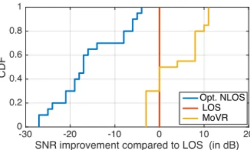
A key promise of MoVR is that it can address the blockage problem. To verify this, we place the AP in one corner of the room and the reflector in the opposite corner. We place the headset at a random location and orientation. The AP trans-mits packets consisting of OFDM symbols and the headset’s receiver receives these packets and computes the SNR. We perform the experiment for 20 runs, changing the location and orientation of the headset for each. We repeat each run for three scenarios: 1) line-of-sight (LOS), where there is a direct path between the AP and the headset receiver. 2) Op-timal non-line-of-sight (Opt. NLOS), where the line of sight is blocked and the SNR is computed by trying all possible combinations of AP and receiver beam directions, picking the one which provides the highest SNR. 3) MoVR is de-ployed in the same blockage scenario as the Opt. NLOS sce-nario and the resulting SNR is measured.
Fig.9 compares the SNRs in all three scenarios. The figure plots the CDF of the SNR improvement relative to line-of sight, defined as follows:
SNR improvement[dB] = SNR scenario[dB] − SNR LOS[dB] The figure shows that, in Opt. NLOS scenarios (i.e., without MoVR), the SNR drops by as much as 27dB and the average SNR reduction is 17dB. As shown in §3, such high reduction in SNR prevents the link from supporting the required VR data rate. Thus, simply relying on indirect reflections in the environment to address blockage does not work.
The figure also shows that, for most cases, the SNR deliv-ered with MoVR is higher than the SNR delivdeliv-ered over the line-of-sight path with no blockage. MoVR performs better than the line-of-sight paths because, in those cases, the AP
-30 -20 -10 0 10 20
SNR improvement compared to LOS (in dB)
0 0.2 0.4 0.6 0.8 1 CDF Opt. NLOS LOS MoVR
Figure 9—SNR Performance: SNR improvement relative to the LOS in three scenarios: line-of-sight (LOS), optimal non-line-of-sight (Opt. NLOS), and MoVR in the same blockage scenario as Opt. NLOS.
distance to the MoVR reflector is shorter than its distance to the headset’s receiver. Thus, the presence of MoVR along the path, and the fact that it amplifies the signal, counters the SNR reduction due to the longer distances to the headset. The figure shows that MoVR performs 3dB worse than the line-of-sight scenario in some cases. This loss does not af-fect the data rate though, due to the fact that, in these cases, the headset is very close to the AP and hence provides a very high SNR (30-35 dB) at the headset’s receiver. This SNR is much higher than the 20dB needed for the maximum data rate. Therefore, losing 3 dB SNR in these cases will not af-fect the data rate. This experiment shows that MoVR enables a high-data-rate link between a VR headset and a PC even in the presence of blockage.
6.
DISCUSSION & CONCLUSION
This paper presents MoVR, a system that delivers mmWave wireless connectivity to VR headsets. It does so by enabling a smart and simple mmWave reflector that can reconfigure itself and adapt its angles of incidence and re-flection to counter the effect of mmWave blockage. The pa-per also presents initial results that show MoVR’s capability. A few points are worth mentioning:
• We have focused on eliminating the high-rate HDMI con-nection between the PC and headset. However, the current headset also uses a USB cable to deliver power. This cable can be eliminated by using a small rechargeable battery. The maximum current drawn by the HTC Vive headset is 1500mA. Hence, a small battery (3.8x1.7x0.9in) with 5200mA capacity can run the headset for 4-5 hours [2] . • Our discussion has focused on delivering a high-data-rate
wireless link to the headset, but a VR headset also requires the link to have low latency. The headset updates the dis-play every 10ms. In principle, all components of our de-sign work much faster than this time scale. Our phased array uses analog phase shifters and is controlled with a high-speed Digital-to-Analog converter, which can be up-dated in sub micro-second time frames. Finding the best beam alignment is the most time consuming process in the design, but one can leverage the tracking information provided by VR system to speed this process. Our future work will focus on designing a fast beam-tracking algo-rithm that leverages this information and evaluating the end-to-end performance of this system.
Acknowledgments: We thank the NETMIT group and the review-ers for their insightful comments. This research is supported by NSF and HKUST. We thank the members of the MIT Center for their interest and support.
7.
REFERENCES
[1] 60 GHz: Taking the VR Experience to the Next Level. http://www.sibeam.com/en/Blogs/2016/March/ 60GHZTakingtheVRExperience.aspx.
[2] Anker Astro 5200mAh battery. https://www.amazon.com/ Anker-bar-Sized-Portable-High-Speed-Technology/dp/ B00P7N0320.
[3] CNET review for Samsung Gear VR.
http://www.cnet.com/products/samsung-gear-vr/. [4] Facebook Expects to Ship 2.6 Million Oculus Rifts by 2017.
http://www.businessinsider.com/.
[5] HTC sold 15,000 $800 Vive virtual reality headsets in 10 minutes. http://venturebeat.com/2016/02/29/.
[6] IEEE 802.16 Broadband Wireless Access Working Group. ieee802.org/16/maint/contrib/C80216maint-05_112r8.pdf. [7] IEEE 802.16 Broadband Wireless Access Working Group.
http://www.keysight.com/upload/cmc_upload/All/ 22May2014Webcast.pdf?&cc=US&lc=eng.
[8] Optoma’s wireless VR headset frees you from PC cables. http://www.pcworld.com/article/3044542/virtual-reality/ optomas-new-wireless-vr-headset-frees-you-from-pc-cables.html. [9] Samsung Gear VR. http://www.samsung.com/us/explore/gear-vr/. [10] Sulon sneak peak. http://sulon.com/blog/sulon-q-sneak-peek. [11] Virtual Apple Airport Express.
http://www.apple.com/airport-express/. [12] Virtual Reality in Entertainment. http:
//www.vrs.org.uk/virtual-reality-applications/entertainment.html. [13] Virtual Reality in Healthcare.
http://www.vrs.org.uk/virtual-reality-healthcare/. [14] Visus VR. http://www.visusvr.com/.
[15] VR for everyone. https://vr.google.com/. [16] Wireless HDMI. http://www.cnet.com/news/
wireless-hd-video-is-here-so-why-do-we-still-use-hdmi-cables/. [17] WorldViz brings â ˘AIJwarehouse-scaleâ ˘A˙I VR to Unreal and Unity
engines. http://aecmag.com/technology-mainmenu-35/. [18] www.ubeeinteractive.comUnderstanding Technology Options for
Deploying WiFi. http://www.ubeeinteractive.com/sites/default/files/ Understanding%20Technology%20Options%20%20for% 20Deploying%20Wi-Fi%20White%20Paper.pdf.
[19] O. Abari, H. Hassanieh, M. Rodreguiz, and D. Katabi. Poster: A Millimeter Wave Software Defined Radio Platform with Phased Arrays. In MOBICOM, 2016.
[20] D. Bharadia and S. Katti. Fastforward: Fast and constructive full duplex relays. In ACM SIGCOMM, 2014.
[21] S. Boyd. Can Virtual Reality Cut the Cord?
http://www.makeuseof.com/tag/can-virtual-reality-cut-cord. [22] S. Boyd. Lecture 12: Feedback control systems: static analysis.
https://stanford.edu/~boyd/ee102/ctrl-static.pdf.
[23] C. S. C. Advanced Techniques in RF Power Amplifier Design. Artech House, 2002.
[24] Y. Cui, S. Xiao, X. Wang, Z. Yang, C. Zhu, X. Li, L. Yang, and N. Ge. Diamond: Nesting the Data Center Network with Wireless Rings in 3D Space. In NSDI, 2016.
[25] J. C. Doyle, B. A. Francis, and A. R. Tannenbaum. Feedback control theory. Courier Corporation, 2013.
[26] M. E. Eltayeb, A. Alkhateeb, R. W. Heath, and T. Y. Al-Naffouri. Opportunistic Beam Training with Hybrid Analog/Digital Codebooks for mmWave Systems. In GLOBESIP, 2015.
[27] P. R. Gray and R. G. Meyer. Mos operational amplifier design-a tutorial overview. IEEE Journal of Solid-State Circuits, 17(6):969–982, Dec 1982.
[28] D. Halperin, S. Kandula, J. Padhye, P. Bahl, and D. Wetherall. Augmenting Data Center Networks with Multi-Gigabit Wireless Links. In ACM SIGCOMM, 2011.
[29] S. Han, C. I, Z. Xu, and C. Rowell. Large-Scale Antenna Systems with Hybrid Analog and Digital Beamforming for Millimeter Wave 5G. IEEE Communications Magazine, January 2015.
[30] J. Kim and A. F. Molisch. Fast Millimeter-Wave Beam Training with Receive Beamforming. Journal of Communications and Networks, 16(5), October 2014.
[31] T. S. Rappaport, J. N. Murdock, and F. Gutierrez. State of the art in 60GHz integrated circuits and systems for wireless communications. Proceedings of the IEEE, 2011.
[32] S. Sur, X. Zhang, P. Ramanathan, and R. Chandra. BeamSpy: Enabling Robust 60 GHz Links Under Blockage. In NSDI, 2016. [33] W. Yuan, S. M. D. Armour, and A. Doufexi. An Efficient and
Low-complexity Beam Training Technique for mmWave Communication. In PIMRC, 2015.
[34] X. Zhou, Z. Zhang, Y. Zhu, Y. Li, S. Kumar, A. Vahdat, B. Y. Zhao, and H. Zheng. Mirror Mirror on the Ceiling: Flexible Wireless Links for Data Centers. In ACM SIGCOMM, 2012.
[35] Y. Zhu, Z. Zhang, Z. Marzi, C. Nelson, U. Madhow, B. Y. Zhao, and H. Zheng. Demystifying 60GHz Outdoor Picocells. In MOBICOM, 2014.