Design of Efficient, Cost Effective Three Phase Induction
Motors for Ceiling Fans in India
ARCHIVES
MASSACHUSETTS INSTITUTE OF TECHNOLOGY
by
Mohammad Mowafaq
Qasim
JUN
13
2019
B.S. American University of Sharjah (2011)
LIBRARIES
S.M. Masdar Institute of Science and Technology (2013)
Submitted to the Department of Electrical Engineering and Computer
Science
in partial fulfillment of the requirements for the degree of
Master of Science in Computer Science and Engineering
at the
MASSACHUSETTS INSTITUTE OF TECHNOLOGY
June 2019
Massachusetts Institute of Technology 2019. All rights reserved.
Signature redacted
Author
....
Certified by
... ...
Department of Electrical Engineering and Computer Science
Signature redacted
May 23, 2019
James L. Kirtley Jr.
Professor of Electrical Engineering and Computer Science
Thesis Supervisor
Accepted by...
Signature redacted
U U
Leslie A. Kolodziejski
Professor of Electrical Engineering and Computer Science
Chair, Department Committee on Graduate Students
Design of Efficient, Cost Effective Three Phase Induction Motors for
Ceiling Fans in India
by
Mohammad Mowafaq Qasim
Submitted to the Department of Electrical Engineering and Computer Science on May 23, 2019, in partial fulfillment of the
requirements for the degree of
Master of Science in Computer Science and Engineering
Abstract
In developing economies such as India, improving the efficiency of home appliances is of high priority in locations which are characterized by a weak electric distribution system. Ceiling fans are one of the most used home appliances in India. They typically operate for many hours, and since most of them are driven by inefficient, low cost single phase induction motors, the total power loss is nontrivial. To overcome the inefficiency of single phase induction motors, brushless dc motors have been increasingly used in ceiling fans to achieve high efficiency and power factor at multiple speed settings. However, they are more expensive than conventional ceiling fan motors due to the additional cost of permanent magnets and power electronic drive circuit.
Three phase in contrast to single phase induction motors have proven to have a superior performance especially for high power applications. From a manufacturing point of view, they are no more expensive to build than single phase induction motors. Also, three phase induction motors require no permanent magnets, which makes them economically attrac-tive. To be able to use three phase induction motors in home appliances at variable speed, a power electronic drive is required to convert the single phase supply to three phase. The drive circuit can also be controlled to improve the input power factor. With the advance-ment of power electronic technology and integrated control devices, such motor drives can be made efficient and cost effective.
This thesis explores the design and optimization of three phase squirrel cage induction motors for the application of ceiling fans in India, with the objective of achieving a bal-ance between efficiency and cost. A detailed analytical model for a low speed, low power three phase squirrel cage induction motor is developed. The analytical model is validated using finite-element analysis. This thesis also optimizes the motor design using genetic al-gorithms. The optimized design weighs 4.5kg and achieves 70% efficiency, which proves more efficient than existing ceiling fan motors in India. The optimized design is also vali-dated in finite-element analysis. Finally, this thesis presents a simulation study of the motor drive implementation for the proposed three phase induction motor.
Thesis Supervisor: James L. Kirtley Jr.
AbWe
And sa,"yLr, nraem i nweg.
Acknowledgments
First, I would like to express my sincere thanks and appreciations to my advisor Professor James Kirtley for his generous teaching, relentless guidance, encouragement and support throughout this thesis. His great knowledge, experience, and enthusiasm for electric ma-chines have inspired me to pursue the field of electric mama-chines. This thesis would not have been possible without his guidance.
I also would like to thank Professor David Perreault for his generous time to answer
my questions related to power electronics. His outstanding teaching, generosity with his knowledge and experience, his great efforts to organize seminars and field trips for graduate students, and his invaluable advice in research, is very inspiring.
During the course of this work, I had the great opportunity to work with Professor Vivek Agarwal and Arpan Hota, our collaborators at the power electronics and power systems group at the Indian Institute of Technology, Bombay. Prof. Agarwal's input on the design of the power electronic drive part of the project has been very valuable. To him, I say "Thank you!". I also would like to thank Arpan whom I have been working with closely for this project. The many technical discussions we had, his accommodation of the time difference in our conference calls, his generous help to acquire and ship the test ceiling fans to Boston, were instrumental in the success of this work.
I would like to express my sincere gratitude to all LEES faculty and staff who have
been very helpful, including Dr. Stephen Umans (whose generosity with time to discuss challenging problems with the machine design and analytical modeling is extraordinary), Professor Steven Leeb (who have played a major role in LEES renovation to provide stu-dents with necessary equipment and lab facility), Professor Jeffery Lang, David Otten and Donna Gale.
Great thanks to my friends and colleagues who have made LEES a great place to work, including Alexander Jurkov, Anas Al Bastami, Colm O'Rourke, Lukasz Huchel, Po Hsu Huang, Krishan Kant, Sajjad Mohammadi, Alex Hanson, Edwin Fonkwe, Matthew Over-lin, William Taft, Yiou He, Rakesh Kumar, Jessica Boles, Tony Zhang, Mike Ranjram, Intae Moon, Adedayo Aderibole, Nathan Monroe, Daisy Green, Jie Mei, and many others.
Words can never do justice to express my gratitude to my family. It is to my parents Mowaffaq Qasim and Wedad Mousa that this thesis is dedicated. I have become what I am now due to them. Their unconditional love, endless care and continuous encouragement are my main source of inspiration. My sister, Mona Qasim, may God bless her soul, was always supportive of my academic pursue, and her belief in me is a treasure I cherish and a motivation to reach to greater heights. Much credit goes to my siblings. It is their love, support and advice that I will not trade for the whole world.
I also would like to express my gratitude to my friends in Boston, including
Mo-hamed Radwan, Edmond Awad, Nasir Almasri, MoMo-hamed Ibrahim, Sally El Henawy,
Shahd Labib, Cynthia Hajal, Christian Adib, Shaheen Tomah, Abdullah AI-Dujaili, Sana
AI-Dujaili, Rabeeya Arif, and many others.
Finally, I would like to thank MIT Tata Center for supporting this research. Special thanks go to Professor Robert Stoner, Professor Chintan Vaishnav and Reja Amatya for connecting me with local ceiling fan companies in India and their great mentor-ship to help me develop the techno-economic analysis for my research. I also would like to thank Usha Limited for providing us with ceiling fans data and efficiency reports.
Contents
1 Background and Motivation
1.1 Problem Statement . . . . 1.2 Thesis Contributions . . . . 1.3 Thesis Outline . . . .
2 Literature Review
2.1 Single Phase Induction Motors . . . . 2.1.1 Split Phase Motors with Resistive Auxiliary 2.1.2 Capacitor Motor . . . .
2.1.3 Shaded Pole Motor . . . . 2.2 Brushless DC Motors . . . .
2.3 Three Phase Induction Motors . . . .
3 Analytical Model
3.1 Extended Equivalent Circuit Model . . . .
3.2 Stator Equivalent Circuit Parameters . . .
3.2.1 Stator Resistance RI . . . . 3.2.2 Magnetizing and Space Harmonics
3.2.3 Stator Leakage Reactance X1 . .
3.3 Rotor Equivalent Circuit Parameters . . .
3.3.1 Skew Effect . . . .
3.3.2 Rotor Resistances R2n . . . ..
3.3.3 Rotor Leakage Reactances X2n.
Winding Reactances 19 21 23 24 27 27 28 29 30 31 33 35 35 37 37 39 43 55 56 57 66 Xm,n
3.4 Core Branch . . . . 3.4.1 Steinmetz Equation . . . . 3.4.2 Core Elements Calculation . . . .
3.5 Performance Evaluation . . . .
4 Verification of Analytical Model using Finite-Element Analysis and Design Op-timization
4.1 Motor Configuration . . . .
4.2 Design Philosophy . . . .
4.3 Initial Design . . . .
4.4 Validation of the Analytical Model in 2D and 3D Finite-element Analysis . 4.4.1 2D Finite-Element Model of the Initial Motor Design . . . .
4.4.2 Three Dimensional Finite-element Model of the Initial Motor Design 4.4.3 Validation Results . . . 9 0
4.5 Design Optimization Using Genetic Algorithm . . .
4.5.1 Design Requirements . . .. . . . 4.5.2 Cost Function . . . . 4.5.3 Genetic Algorithm . . . . 4.5.4 Optimization Variables and Fixed Parameters 4.5.5 Optimization Results . . . . 4.6 Optimized Motor Design for Ceiling Fans . . . . 4.7 Sensitivity Analysis . . . . 4.7.1 Sensitivity Analysis Setup . . . . 4.7.2 Sensitivity Analysis Results . . . .
. . . 94 . . . 94 . . . 95 . . . 96 . . . 97 . . . 98 . . . 105 . . . 109 . . . 109
. . . 110
5 Evaluation of the Optimized Three Phase Induction Motor with the Adjustable Speed Drive 115 5.1 Three Phase Induction Motor Drive Circuit and Volt-Hz Speed Control . . 116
5.2 M otor Simulation M odel . . . 116
5.3 Sim ulation Results . . . 1 19 69 69 71 74 85 85 85 86 87 88 89
6 Summary and Conclusions 123 6.1 Thesis Summary . . . 123 6.2 Thesis Conclusions . . . 124
List of Figures
1-1 Block diagram of three phase induction motor with power electronic drive
circuit: the motor drives home ceiling fan . . . . 22
2-1 Split phase induction motor . . . . 29
2-2 Capacitor start motor . . . . 30
3-1 Extended equivalent circuit model of three phase induction motor . . . . . 36
3-2 Rectangular semi-closed stator slot of a double layer winding . . . . 44
3-3 Ampere's loops to derive magnetic field in different regions of the slot . . . 45
3-4 Snippets showing the phase sequence of a double-layer winding as it is being short-pitched from pf 1 to pf = 2/3: (a) full-pitch pj = 1, (b) short-pitched 2/3 < pf < 1, (c) short-pitched pf = 2/3 . . . . 51
3-5 The nh order transformer element of the per phase equivalent circuit in-cluding the skew effect . . . . 57
3-6 Rectangular rotor slot . . . . 58
3-7 Planer circuit representing cage of an induction motor . . . . 60
3-8 Rotor bar current assumed to be sinusoidally distributed around periphery 63 3-9 Equivalent circuit reduced to the terminal voltage in series with terminal im pedance only . . . . 78
4-1 Outer-rotor, inner-stator three phase squirrel cage induction motor pro-posed for ceiling fans application . . . . 86
4-2 B-H curve of M19-26G electrical steel showing saturation characteristics of the stator and rotor core . . . . 88
4-3 2D image of the initial design motor (unoptimized) . . . . 89
4-4 Flux density distribution at speeds (a) 300 RPM (left) and (b) 0 RPM (right) 90 4-5 A picture showing the 3D FE model of the initial design simulated in
AN-SYS Maxwell 3D transient analysis . . . . 91
4-6 Magnetic flux density distribution in the 3D FE model of the initial motor
design . . . 9 1
4-7 Meshed 3D FE model of the initial motor design . . . . 92
4-8 Evaluation of initial design by the analytical Model and 2D FEA model in ANSYS: (a) torque (Te), (b) input power (Pa), (c) mechanical power (Pmech), (d) efficiency (q%), (e) power factor (pf), and (f) terminal current (Ia) vs speed in RPM . . . . 93
4-9 Pareto frontier reached by GA illustrating efficiency versus active weight for the different optimization objectives: (a) an = 1 am = 1, (b) an = 1 a'n =0, (c) an = 0 a, = 1, (d) an = 4 am = 2, (e) an = 2 am = 4, (f) an =4 an = 1, (g) a = 3 am = 4 . . . 101 4-10 Evaluation of each optimized motor design by the analytical model: (a)
torque (T,), (b) input power (P1 ), (c) converted mechanical power (Pmech),
(d) efficiency (7%), (e) power factor (pf), and (f) terminal current ('a) vs
speed in RP M . . . 104
4-11 Optimal solution found by GA corresponding to each optimization run ob-jective function: (a) efficiency (b) active weight . . . 105
4-12 2D FE model of optimized motor design . . . 106
4-13 Mesh at different regions of the 2D FE model of the optimized motor design 107 4-14 Verification of analytical optimized design (an = 4, am = 2) using Maxwell
2D FEA: (a) torque (T,), (b) input power (Pa), (c) converted mechanical
power (Pmech), (d) efficiency (7%), (e) power factor (pf), and (f) terminal
4-15 Contour maps showing the sensitivity of efficiency and active weight against two optimization variables around the optimal solution at rated speed (de-sign 4): (a) g and I versus y% and (b) g and I versus Al, (c) Ke.,, and h,
versus q% and (d) Kt,,, and h, versus Al (e) d, and ur versus q7%, (f) d, and u, versus Al . . . 112
4-16 Contour maps showing the sensitivity of efficiency and active weight against two optimization variables around the optimal solution at rated speed (de-sign 4): (a) Kt,, and h, versus i7%, (b) Kt,, and h, versus M, (c) d, and u, versus r7%, (d) d, and u, versus Ai(e) her and 1e, versus r7%, (f) he, and ler versus Al . . . . 113
5-1 Proposed three phase induction motor system to drive ceiling fans: (a) over-all motor system, (b) volt-Hz speed control and pwm generation . . . 117 5-2 D-q simulation model of squirrel cage induction motor: (a) d-axis
equiva-lent circuit, (b) q-axis equivaequiva-lent circuit . . . 119
5-3 Steady state simulation results of the optimized three phase induction mo-tor driven by a three leg inverter using volt-Hz control: (a) electromagnetic torque, T, (N.m), (b) rotor speed, N (rpm), (c) stator currents, I (A), (d) drive input power Pa (W), (e) mechanical power, Pmech (W) and (f) dc link voltage, Vc (V ) . . . 122
List of Tables
3.1 Self, mutual, and leakage coil-pitch factors . . . . 55
4.1 Motor data of the initial design . . . . 87
4.2 Three phase induction motor equivalent circuit parameters of the initial design 88 4.3 Flux densities in the rotor and stator at 0 RPM . . . . 90
4.4 Design requirements . . . . 95
4.5 GA settings . . . 97
4.6 Motor design optimization variables . . . . 97
4.7 Fixed parameters in the motor design . . . . 98
4.8 Exponents of the optimization attributes of the eight different optimization schem es . . . . 99
4.9 Optimized motor data found by the GA for the different optimized designs . 102 4.10 Equivalent circuit parameters for the different optimized designs . . . 103
Chapter
1
Background and Motivation
Electric motors are the single largest electrical load, accounting for 43% of all global elec-tricity consumption in 2006, 9% of which are appliance motors used in the residential sector [64]. Among the highest energy-consuming electric motor driven appliances are refrigerators, heating, ventilation and air-conditioning (HVAC) systems, pumps, and fans. The performance of these motors are characterized by three indices: efficiency, power fac-tor, and current distortion. Each of the indices are of a particular interest to emerging economies such as India, which is characterized by a relatively weak power system, and relatively large number of isolated distribution systems that can be considered microgrids. For example, on July the 30th, 2012, the largest power outage in history, which affected most of northern and eastern India, left more than 600 million people in the dark. These power outages, planned and unplanned, are not only due to the large energy demand, but also due to inefficiencies at both the distribution and consumer ends. A lot of home ap-pliances driven by motors are being produced and increasingly used in India by a large population which is constantly increasing as individuals get wealthier. Therefore, hun-dreds, if not thousands of Terra-Watt of energy, can be saved annually by adopting efficient appliances at the consumer end. One of the inefficient appliances that are widely used in India are ceiling fans.
Fans are the main source of residential cooling in India as opposed to air-conditioning systems in the developed countries. It is reported that they accounted for 6% of the total residential energy use in India in 2000 and is expected to account for at least 9% in 2020
[19]. Furthermore, fans are also well-known to be a cost-effective solution for reducing
air conditioner electricity consumption. Therefore, improving the performance of electric motors that drive ceiling fans can play an important role in reducing the overall energy consumption in many countries, not only in India. Furthermore, a study on the potential global benefits of improving ceiling fan energy efficiency [50] shows that using the existing motor technology, 50% improvement on the motor efficiency can be achieved which results in more than 50 Terra-Watt-Hour energy saving by 2020 in India.
The most commonly used motor for driving fractional horse power appliances is the single phase induction motor. Two common types of single phase induction motor are widely used for driving ceiling fans: shaded pole induction motor [56] which is popular in Europe and the United States, and permanent split capacitor induction motor [14], prevalent in India. Ceiling fans driven by these motors have a power consumption of 70 W [16]. Another type of ceiling fans motors that are becoming more popular is brushless DC motors (BLDC). BLDC motor is a permanent magnet synchronous motor driven by solid state devices. It had first appeared in 1962 by William and Trickey [66]. In that time, these motors were not economically attractive due to the high cost of permanent magnets and power electronics. With the advancement in semi-conductor technology, BLDC motors have succeeded to replace conventional brush DC motors in the higher horse-power range
[35]. However, it was not until 2009 when BLDC motors came into the ceiling fan industry
in the US, and a few years later in India.
Ceiling fans driven by BLDC motors are efficient and can operate over a range of speeds since they rotate in synchronism with the airgap magnetic field (no slip loss), provide exci-tation at no loss by the PMs, and operate over a range of speeds by a power electronic drive circuit. They are considered the most efficient in the household fan market, as they draw less power in the range of 28 -35 W as at rated speed compared to the 70 W conventional
ceiling fan. However, they are more expensive than the conventional single phase induction motors due to the added cost of the permanent magnets and power electronic circuit.
Three phase induction motors, are simple, rugged, easy to build, and reliable. Gener-ally, they can be designed to have a satisfactory efficiency and can be operated stably at variable speeds by a suitable power electronic drive circuit. However, it is still considered
until now unconventional to use three phase induction motors in low power applications such as home appliances. The main reason is the absence of three phase supply in house-holds. However with semiconductor power devices becoming increasingly cheaper, it is worth considering three phase induction motors for powering home appliances due to their aforementioned advantages. For example, Arpan et al. [27] have shown that a power elec-tronic drive system for three phase induction motors of domestic fan applications can be made cost effective, efficient, and more reliable by using a simple dc-link capacitor reduc-tion strategy accompanied with a modified PWM scheme [27]. In this thesis, we attempt to show that three phase squirrel cage induction motors, equipped with a power electronic drive, can be designed with relatively high efficiency and satisfactory power factor for ceil-ing fans.
1.1 Problem Statement
The distribution electric grids are relatively weak in India. Part of their inefficiency is due to the use of inefficient loads and appliances at the consumer end. Ceiling fans is a primary appliance that is used in almost every house in India. The majority of these ceiling fans use single phase induction motors which are quite inefficient. The existing ceiling motor technology, such as brushless dc motors or improved design of split phase induction mo-tor through means of thinner laminations (affect eddy current losses), romo-tor bars of copper instead of aluminum (affect conduction losses) and smaller airgap (affect torque), can po-tentially reduce power consumption of conventional ceiling fans by 50% or more, resulting in great savings. However, this comes at the expense of cost. For example, the price of a BLDC ceiling fan is four times more expensive than the conventional capacitor-run motor ceiling fan, which makes it economically unattractive and sometime unattainable to many end-users in India. Similarly, improved lamination, and higher rotor bar conductivity adds to the cost of SPIMs. Thus, designing a motor is a challenging task of achieving a balance between many trade-offs, such as efficiency, power factor, cost, weight, volume, etc.
The two types of ceiling fan motors (SPIMs and BLDC) showcase a situation of con-flicting requirements, namely efficiency and cost. The first type of motor is inexpensive
to manufacture but its efficiency is limited, and can be designed to operate at maximum efficiency and power factor only at a single speed. However, the second motor is inherently efficient, and being driven by a power electronic package enables variable speed operation without using lossy resistors as in SPIMs. The main drawback of this motor is its higher cost, which is primarily due to its PMs and secondarily due to the cost of power electron-ics. Reaching to a middle ground between these two technologies is a challenging task, nonetheless attainable by induction motors with a smart control. Three phase squirrel cage induction motors can provide the balance between efficiency and cost since they are fairly efficient, do not require PMs, and can be driven at variable speeds using a power electronic package while maintaining high efficiency at lower speeds. In this thesis, a three phase in-duction motor driven by a power electronic circuit at variable speeds is proposed for ceiling fans in India.
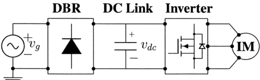
The proposed motor system for ceiling fans is shown in Fig. 1-1. It consists of a three phase induction motor, a power rectifier, and DC link capacitor followed by an inverter. The rectifier is used to convert the AC power to DC, stored in the form of electric energy in the dc link capacitor. The inverter is controlled by a microcontroller and pulse-width-modulation scheme to convert the DC power into three phase AC power suitable for driving the three phase induction motor. The motor can operate at several speeds via Volt-Hz open loop control implemented by the microcontroller upon receiving an input command from the fan's remote control or a speed control knob.
DBR
DC Link Inverter
'V
V
9jd
4-I
Figure 1-1: Block diagram of three phase induction motor with power electronic drive circuit: the motor drives home ceiling fan
1.2 Thesis Contributions
This thesis explores the design of squirrel cage induction motor for household ceiling fans in India with the objective of achieving overall improvements and balance between ef-ficiency, and cost to overcome the inefficiency of single phase induction motors used in conventional ceiling fans and the higher cost of brushless dc motors of the new generation of ceiling fans. The thesis contributions are summarized as follows:
(1) The analytical model of the three phase squirrel cage induction motor is developed,
considering higher order space harmonics and core losses. The authors adopts the methods shown by P. Alger [3], J. Kirtley [31] and T. Lipo [38] in developing the an-alytical model. The calculation of the equivalent circuit parameters are described in detail and the performance of the motor is evaluated based on solving the equivalent circuit. A detailed procedure on evaluating the performance of the motor based on
the analytical model is summarized.
(2) The analytical model is validated in 2D and 3D finite-element (FE) transient analysis
in ANSYS Maxwell.
(3) Based on the verified analytical model, an optimized motor design is obtained by
employing genetic algorithm optimization. Several optimization objective functions were explored, and an optimal design is chosen to satisfy the best compromise be-tween efficiency and weight (and thus cost). The selected optimized motor design has 70% efficiency (21.4W input power, 15W mechanical power), has 0.5 power factor, weighs 4.5kg, which proves superior to existing ceiling fan motors in terms of energy consumption. The optimized motor maintains an overall high efficiency (60% to 70%) as the load is varied. The input power factor can be corrected if required by provision of a power factor correction circuit added to the drive circuit.
(4) The optimized motor is validated in Maxwell 2D FE transient analysis.
(5) The optimized motor with the power electric drive circuit is evaluated in
instantaneous torque, input power, mechanical power, and stator currents approxi-mates that calculated from the analytical and FE models.
1.3
Thesis Outline
This thesis is divided into six chapters including this introductory chapter. Chapter 2 sur-veys the different type of motors used in ceiling fans, specifically single phase induction motors and brushless dc motors. The final part of the chapter discusses three phase induc-tion motors in general as they are the proposed type of motors in this thesis for ceiling fans application.
Chapter 3 discusses the analytical model for squirrel cage induction motors in detail. This analytical model has the merit of describing the terminal behavior of the motor using a simple equivalent circuit model. The per phase equivalent circuit model is also discussed and the analytical expressions for the circuit parameters are provided. Furthermore, this chapter presents a detailed procedure on evaluating the performance of the motor through means of solving the equivalent circuit.
Chapter 4 presents the validation of the analytical model in 2D and 3D FE transient analysis in ANSYS Maxwell, and optimization of the motor design using a genetic algo-rithm optimization technique. The chapter starts by verifying the performance of initial design of the motor using finite-element models and then uses the analytical model to op-timize the motor design. The second part of the chapter explores and compares between different optimization objective functions to reach to a trade-off between efficiency and active weight of the motor. The third part of the chapter selects an optimum design and presents the validation results of the optimized motor design in finite-element transient analysis.
Chapter 5 investigates the performance of the optimized induction motor with the power electronic drive circuit using d-q simulation dynamic model in MATLAB/Simulink. It is shown the optimized design of the proposed ceiling fan three phase phase induction motor can be driven by low cost variable speed drive with simple volt-Hz open loop control. The
flux density of the optimized motor. The second part of the chapter compares the steady state torque, input power, mechanical power, and stator currents obtained from motor with drive Matlab/Simulink simulations with those obtained from the analytical model and FE
transient simulations.
Finally, Chapter 6 provides a summary of the ground covered in the thesis and presents recommendations for future work.
Chapter 2
Literature Review
There are two main type of motors used to drive ceiling fans: single phase induction motors and brushless dc motors. Single phase induction motors were prominent in driving home ceiling fans until 2009 when Emerson Electric introduced their first brushless dc motor ecofan model. Now, most efficient (and more expensive) ceiling fan motors use brushless dc motors. In this thesis, three phase induction motors equipped with power electronic drive circuit is proposed for household ceiling fans as the can be designed with higher efficiency than single phase induction motors, and lower overall cost (including cost of the drive) than brushless dc motors. In this chapter, we will give a brief background the major motor technologies used in the ceiling fan industry, including single phase induction motors and brushless dc motors. We will also attempt to provide a general background about three phase induction motors and shed light on the major contributions in the modeling, design, optimization and drives of appliance motors.
2.1
Single Phase Induction Motors
From a structural point of view, single phase induction motors (SPIM) resemble three phase induction motors in structure with a difference only in the stator winding. The stator wind-ing in swind-ingle phase induction motors consists of two coils 90 electrical degrees displaced in space, such as in split phase motors and one winding in shaded pole motors. The rotor, on the other hand, is the same as in three phase squirrel cage induction motors. In fact, if one
of the phases of a three-phase induction machine was opened while the motor is running at rated speed, the machine may continue to operate as a single phase motor with line-to-line voltage across the other two connected lines. The same motor, however, will not restart with single phase supply according to the double revolving theory [57,62].
The double revolving theory states that a stationary pulsating magnetic field of single phase motor can be decomposed into two revolving magnetic fields of equal magnitude but rotating in opposite directions. The induction motor will respond to each magnetic field separately producing its own torque-speed characteristic curve, and the net torque is the su-perposition of the two torques produced by the forward and backward magnetic fields. By symmetry and superposition, such a motor inherently produces no starting torque at stand-still, as the two oppositely rotating magnetic fields produce torques of equal magnitude and opposite signs. However, if the motor was started by auxiliary means, the net torque will be in the direction in which it is started, and the motor will naturally continue to run. This torque is the average torque, however the instantaneous torque will be alternating at twice the line-frequency of the stator with zero average per cycle. This pulsation will cause the motor to vibrate making it noisier than a three phase induction motor of the same size. This inherit vibration must be allowed for in the mechanical design of the motor [62].
As mentioned earlier, SPIMs can be started by auxiliary means, and are commonly classified according to their starting technique into three main categories: split-phase with resistive auxiliary winding, split phase with capacitive auxiliary winding known as ca-pacitor motors, and shaded-pole motors. Selection of the appropriate motor is based on the efficiency, power factor requirements, starting and running torque requirements of the load, and the limitations on starting and running current drawn from the supply line [57].
2.1.1
Split Phase Motors with Resistive Auxiliary Winding
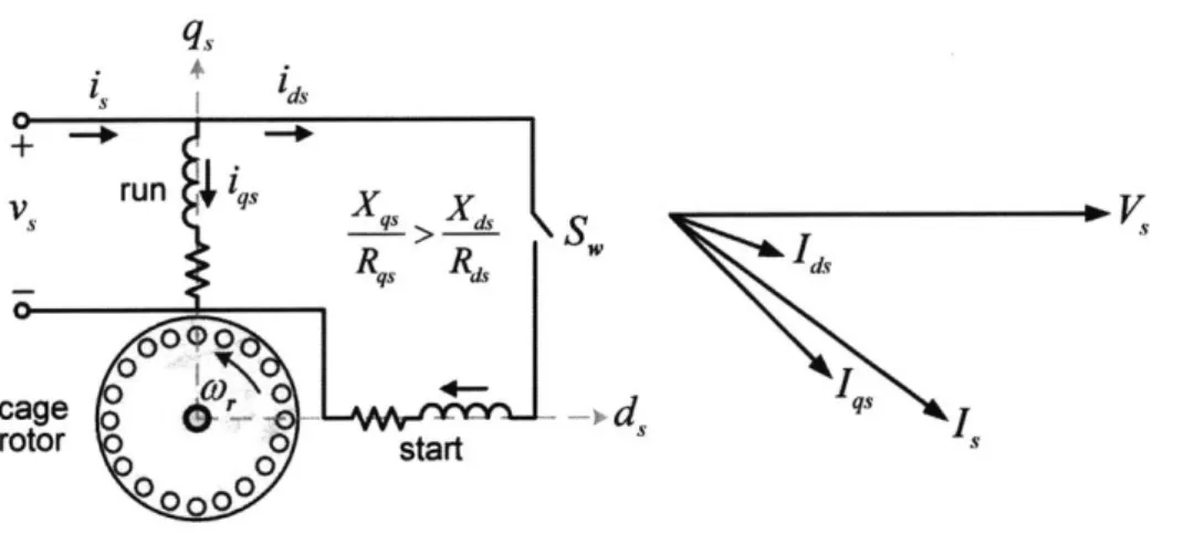
Split phase induction motors have two windings: the main winding and the auxiliary wind-ing as shown in Fig. 2-1. The axes of these windwind-ings are set 90 electrical degrees apart in space along the stator. The main windings have a lower resistance-to-reactance (R/X) ratio than the auxiliary winding, and hence the current in the auxiliary winding leads the
rent in the main winding [31,57]. This means that the flux density of the auxiliary winding
peaks before that of the main winding, making one of the oppositely rotating magnetic field
stronger than the other providing a net starting torque for the motor. The direction of
rota-tion of the rotor is determined by whether the space angle between the main and auxiliary
winding is +90 or -90 electrical degrees. Thus the direction of rotation can be reversed by
switching the connections of the auxiliary winding. To obtain a higher R/X ratio for the
auxiliary winding, a smaller wire than the main winding is usually used for that purpose.
Although the auxiliary winding have higher losses due to the higher resistance, it is used
only at the stating of the motor as it is disconnected later via a centrifugal switch once the
rotor reaches up to 75% of synchronous speed. Split-phase motors have moderate stating
torque with a fairly low stating current. Their efficiency is typically from 40 -55%. Typical
appliance that use SPIM include blowers, centrifugal pumps, and fans.
is I ds
V S
run's
X X S W Rqs R Idscage
d
qsrotor
o
start
0Figure 2-1: Split phase induction motor
2.1.2
Capacitor Motor
The capacitor start motor is a split phase motor, but the time-phase displacement between
the two currents is provided by means of capacitor connected in series with the auxiliary
winding (2-2). By the choosing the right value of capacitance, the auxiliary current can
be designed to lead the main current at 90 electrical degrees, resulting in uniform rotating
field. Similar to the split-phase motor, the auxiliary winding is disconnected after the motor
the motor has started. In permanent-split-capacitor motor, the capacitor is not disconnected
._M
-from the auxiliary winding after starting. Capacitor-type motors have better starting and running torques as compared to split-phase motors, and thus can be used to start loads that require higher starting torque. Furthermore, in case of permanent-split-capacitor motor, the power factor, efficiency, and torque pulsations can be improved by designed for perfect
two-phase operation at any one desired load condition. The capacitor can smooth out the
pulsations in input power and torque improving the overall efficiency and power factor, but
at the expense of a lower starting torque [3,57,62].
This type of motor is widely used for the ceiling fans in India due to its low cost. They
are usually rated for 70W power and deliver not more than 20W mechanical power at rated
speed making them inefficient. This suggests that even with improved designs of capacitor
motors, better efficiency can be achieved at the expense of slight increase in cost. For example, some ceiling fan manufacturers in India, such as Usha [58], have in the market 50W capacitor motor ceiling fans.
i
4i
V
run
ri qs _Xq X LS Is-Rqs Rd, is
0 P 0 Cstart I
rotor
cage0
0start
tr0
Figure 2-2: Capacitor start motor
2.1.3
Shaded Pole Motor
Shaded pole motors have only one main winding, and instead of auxiliary winding, they have salient poles with one portion of each pole surrounded by a short-circuited coil called a shading coil. Time-varying flux in the main winding induces voltage and current in the shading coil. This causes the flux in the shaded pole to lag the flux in the other portion resulting in a rotating magnetic field in the direction from the unshaded to the shaded
portion of the pole [13,17, 18,44,45,56,57,59,62]. A low starting torque is produced from this process. This type of SPIM has the lowest efficiency (~ 40%), however, they are can be attractive in some appliances due their low cost. Conventional ceiling fans in the United States use this type of motor due to their relatively low cost and extreme simplicity.
2.2
Brushless DC Motors
Brushless de motors are electronically commutated permanent magnet (PM) synchronous motors. They are driven with rectangular waveform supply as compared to PM syn-chronous motors which are usually driven by a sinusoidal supply. They are commonly of surface mounted magnets morphology with magnets mounted on the surface of the rotor and a conventional stator winding similar to that of poly-phase induction motor. Brushless dc motors work based on the interaction of the magnetized stator coils and the permanent magnet. The stator coils are energized in such a way that there are forces of attraction and repulsion between the stator and rotor poles to produce the highest torque possible. The main outstanding feature of brushless dc motors is their dc torque output, unlike SPIMs which have an inherently pulsating torque. As the name suggests, brushless dc motors have no brushes, thus are commutatorless unlike conventional PM dc commutator mo-tors. Therefore, they clearly have no brush maintenance cost, and are considered relatively 'safer'to operate in inflammable environments due to the absence of the sparking associ-ated normally associassoci-ated with brushes [421. Moreover, brushless dc motors have larger surface area available for the armature winding as opposed to commutator motors, and thus can withstand higher current densities enabling them to produce larger torque. With the aforementioned advantages, brushless dc motors tend to have higher efficiencies compared to commutator motors of the same size.
Compared to three phase induction motors, brushless dc motors have higher efficiency and power factor assuming the same size and cooling scheme. Both brushless dc motors and adjustable speed drives for three phase induction motors consist of the same power electronic components: a rectifier (if required) followed by a three leg inverter. However, the control scheme for brushless dc motor is simpler than pulse-width-modulation
switch-ing scheme typically employed in induction motor drives. Nevertheless, brushless dc mo-tors comes with certain disadvantages. The weight and hence the cost of the PM increases with the size of the motor. Thus, brushless dc motors are usually used in applications with relatively low power due to the increased cost of the PM. For high power rating, induc-tion motors become more attractive in terms of cost effectiveness, and their efficiencies improve. Furthermore, induction motors are capable of operating in the flux weakening re-gion, enabling them to deliver constant power at higher speeds (above synchronous speed). This is more challenging to achieve in brushless dc motors, especially with larger machines at high speeds, where the PM are mounted on the rotor (mechanical constraint) [42].
The increased reduction in cost and power electronics have made brushless dc motors increasingly used in commercial, industrial, and medical technologies. Among their ap-plications are computers (printers, hard disk drives), hand-held power tools, actuators for computer numerical control (CNC) machines, industrial robots, medical equipment and electric vehicles. Since 2012, there is a new trend in India to move towards brushless dc motors for super efficient ceiling fans. Recently brushless dc motor ceiling fans in India have reduced their power consumption to < 30W at rated speed [54] at the sacrifice of four times the price of a conventional 70W ceiling fan.
Nowadays, brushless dc motors have been increasingly used in household and com-mercial fan applications. This has led to more research effort in the area of single-phase brushless dc motor design and drives (single phase refers to the power outlet supply). In particular, researchers are exploring methods and modeling tools to assist in designing brushless dc motors and their drives for appliances. For example, in [23], M. Fazil et al. propose a nonlinear dynamic model for brushless dc motors for ceiling fan application to reduce the simulation time compared to transient finite-element-model. Furthermore, in [46] a stator shape optimizing design is proposed to reduce the cogging torque of single phase brushless dc motor. As brushless dc motors is not the main focus of this thesis, we refer the authors to [4,15,21,29,36,39,40,49,51,67,69] for more literature on drive control strategies and design of single phase brushless dc motors for small power applications.
2.3
Three Phase Induction Motors
Three phase induction motors come mostly in large sizes, and in the aggregate, consume the largest amount of energy in the electric power grid. They are built for a wide range of applications ranging from fractional horse power up to few mega Watt power applica-tions [1, 2] due to their simplicity, ruggedness, and economical importance. The induction motor can be thought of an electric transformer whose magnetic circuit is divided by the airgap into two parts: the stator and the rotor, moving relative to each other and one carry-ing the primary and the other the secondary windcarry-ings [3]. Their stator is of conventional structure which consists of three windings inserted in slots spatially displaced 120 electri-cal degree apart from each other. The stator winding can be either distributed, such as in large machines or concentrated such as in fractional horse applications. When the stator is excited by a three phase supply, a flux traveling wave is produced and as it cuts the rotor conducting elements, a voltage and thus current is induced in the rotor circuit. The inter-action of the induced currents with the traveling wave creates electromagnetic torque that causes the rotor to rotate [3,31,57].
Three phase induction motors are classified into two types based on their rotor circuit: wound rotor, and squirrel cage induction motors. Wound rotors have rotor windings similar to that of the stator, and their terminals are connected to slip rings mounted on the shaft. Mounted on the slip rings are carbon brushes bearing which provides access to the terminals of the rotor circuit. The advantage of wound rotors is that the rotor resistance can be adjusted, and thus the starting torque can be controlled. Wound rotors are less common than squirrel cage rotors, and they are generally used for specialized applications. Cage rotors, on the other hand, have rotor bars inserted in the slots instead of a conventional winding. The rotor bars are short circuited from both ends with end-rings. Rotor bars and end-rings are usually made of aluminum for low cost motors, and copper for high performance motors. The simple structure of cage induction motors and their economic
value made them more prevalent over wound rotors
Since the invention of induction motors by Nikola Tesla in 1886, extensive research has been done on the modeling of poly phase induction motors. From the vast research
published on the behaviour of poly phase induction machines and efforts that developed analytical models which aimed to describe their behaviour, we attempt here to give credit to the early research by citing some classical papers published in that area [7,8, 10, 11, 22,
24,33,41,48,52,53,60,61,63].
With the advancement of semiconductor technology, power electronic devices, sensors, control circuitry, and microcontrollers, speed adjustable drives have become almost ubiq-uitous in induction motor applications. The power electronic drive usually consist of a rectifier (three phase or single phase depending on the size of the motor) followed by a six switching device inverter. With proper sensing of stator currents, voltages and in some cases rotor position, an open loop or closed loop feedback control scheme is employed by analog circuitry (using operation amplifiers) or digitally in micrcontrollers to generate the gate pulses for inverter switches to achieve torque or speed control. Selected references on control and drives of poly phase induction motors can be found in [9,20,26,28,34,55,68].
As power electronic devices continue to advance in size and cost, using three phase induction motor equipped with adjustable speed drives for home appliances is becoming more viable economically. In this thesis, we attempt to design a three phase induction motor for < 30W household ceiling, which is driven by a power electronic circuit. In the next chapter, the analytical model of three squirrel cage induction motor is developed and discussed in detail.
Chapter 3
Analytical Model
The analytical model of three phase induction motors has been extensively studied since the invention of induction motors by Nikola Tesla. Although their basic operating principle is relatively simple, deriving a mathematical model that exactly predicts the behaviour of induction motors is quite difficult. Nonetheless, analytical models which attempt to describe the behaviour of induction machines through means of equivalent circuit have proved to be simple, tractable, and provide reasonable approximation to the real machine. In this chapter we provide the analytical model of three phase induction motors represented
by a general equivalent circuit model.
This chapter is organized as follows. The general equivalent circuit model of three phase induction motors is described briefly in Section 3.1. Then, in Sections 3.2 - 3.4 the equivalent circuit parameters are derived and expressions to calculate each circuit pa-rameter is provided. Finally in Section 3.5, steps to evaluate the performance of three phase induction motors based on the solving its equivalent circuit is outlined. Torque, in-put power, outin-put power, efficiency and power factor are among the performance metrics used to evaluate a certain design.
3.1
Extended Equivalent Circuit Model
The notion of the equivalent circuit model of induction motors goes long back since its invention in the late I 9th century. It is inspired by the fact that the physics of induction
R, ]X1 'a Vag
V
s,, R Va 12,1 jX2,1 jXc jXm,1 R2,, SI I2,5 Vag,SjXm,
5jX2,5
R2,5 jX2,7 Vag, 7jXm,
7 2,7 S7 I2,z. + jX 2,z. Vagz X,z R2, +jX
2,z. Vag,Z+ jXm,z. R2,z. sz.Figure 3-1: Extended equivalent circuit model of three phase induction motor
motors are similar to transformers as both works based electromagnetic induction. The
purpose OF the equivalent circuit model is to provide a relatively simple analytical model
of the electromechanical system that represents its terminal behavior, and provides a
sim-ple way to predict its performance including torque, converted power, efficiency, and power
factor. There is a vast literature that deal with induction motors from first principle,
how-ever, the authors have relied heavily on J. Kirtley's course notes [31], P. Alger's [3], T.
Lippo's [38], and S. Uman's [57] books to develop the analytical model. The extended
single phase equivalent circuit model of three phase induction motors is shown in Fig. 3-1.
As described by Alger [3], one phase of the induction motor winding can be thought of
a series connected impedances.
In the depicted circuit model, R1 denotes to the stator resistance, X1 is the stator leakage
reactance, X' is the magnetizing reactance of the nth space harmonic component of the airgap flux of the stator winding, R, and X, are the core loss impedance elements in the stator core behind the slots (back-iron) and stator teeth, R,sni models the no-load stray loss in the rotor teeth due to the modulation of the fundamental airgap flux by the stator teeth [31], R2,, and X2-, are the rotor resistance and leakage reactance referred to the stator
due to the nth space harmonic component of the stator airgap flux. The harmonic orders, n = 2k T 1 = 5, 7 refer to the negative (backward rotating) and positive (forward traveling) phase-belt harmonics for three phase machines { k is number of phase-belts or phases thus
k = 31, whereas, n = z+ = -F 1 subscripts refer to the zigzag negative and positive
space harmonic orders, respectively, wherein N, is the number of stator slots, and p is the number of pole pairs. The calculation of the circuit parameters are provided in the following subsections.
3.2
Stator Equivalent Circuit Parameters
3.2.1
Stator Resistance R
1Assume the mean length of a turn can be approximated by simply following the path that a conductor takes to form a loop around one pole pitch,
27r -de - A
c + 2px 2 (3.1)
where, 1 is the axial length of the stator stack (usually known as the active length), Dsg the stator airgap diameter (stator outer diameter), d, the stator depression depth (see Fig. 3-2),
h. the stator slot height, and p is the number of pole pairs. Note that the expression in (3.1) does not account for any extension lengths.
coil (Ie) times the number turns in series per phase or simply what we refer as the number of turns per phase (Na). Thus, the stator winding length per phase is,
11
= Na -1c27r (D.9 - ds - hg = Na -+ + x 1 2 (3.2)
1 2 P_
The area of one wire/conductor is the slot area divided by the number of series con-nected turns per coil. Furthermore, the packing factor should be taken into account as well. The area of one conductor (A,) can thus be expressed in terms of the stator slot area (AS.10.), packing factor (,c), and number of turns per coil (Nc) as:
AW = se Assi0 t (33)
n., 2N,
where n, is the number of turns of in series in a slot, and is equal number of coil sides multiplied by number of turns per coil side, and thus n, = 2Nc. Also, note that a packing factor (Kc) of - 0.3 - 0.5 is typical for random-wound electric machines. In this design
KeU = 0.45 is assumed.
From Ohm's law, and using (3.3) the stator resistance can be expressed as:
R, 1-A1
Nalc N,
=2NcNa 1C (3.4)
JcuKcuAssoi(t
where oc, is the electrical conductivity of copper. Throughout this design, the conductivity of copper is considered at 25'C: a,,, = 5.84 x 10⁷S/m.
turns per phase as: R1 = 4NcNa 2 _ Na Ic/2 Ns3 "cuKcuAssiot = 12 a 1C/2 (3.5)
X5
(7(U Iuc A .eslot where, 1c is as given by (3.2).3.2.2
Magnetizing and Space Harmonics Reactances X,
The fundamental space component of the stator inductance forms the magnetizing induc-tance of the equivalent circuit, whereas higher order space harmonic components of the stator airgap flux density contribute to stator leakage flux, as it does not contribute to real power or useful torque, rather to reactive power that is associated with losses. By superpo-sition, these higher space harmonic inductances are stacked in series with the magnetizing branch forming higher order airgap inductances, as shown in Fig. 3-1.
For a three phase squirrel cage induction motor, excited by three voltage source, the peak of the radial air gap flux density can be expressed as:
3 2 po(Nakw,n)Ia
32ii(a=
nI = 1, 5, 7, 11, (3.6)2 n7r pge
where /o = 47 x 10- 7 I/m is the permeability of air, N number of turns per phase, 'a
terminal current in rms, p number of pole pairs, g, effective airgap depth, and k... is the
winding factor at the nut/ space harmonic order.
The effective airgap depth g, in (3.6) is the corrected airgap depth by carter's coefficient. Carter's suggests [38] that the slotted surface of the stator and rotor can be replaced with unslotted surface with the same cross section but with modified equivalent airgap depth:
ge = (3.7)
--Y _U + 4g n(1I + ,,,)
KC
where g is the physical airgap depth and K, is Carter's correction factor. The airgap is corrected for both the stator and rotor slots:
ge Kc,s - Kc,? g (3.8)
g- Ty's T-Y1r T-y Ur ) g (3.9)
ge rY,s - u. + k In( + 'sus" T-,r - Ur + 49 In(I + 4'g"
The winding factor (ke,) seen in (3.6) is the product of the pitch (kp,,) and breadth (kb,,)
{
distribution} factors and can be expressed as:kwn = kP,, x kb,n (3.10)
na (n,)r sin(n"^E)
= sin( -) sin-) 2 (3.11)
2 2 ,m -
sin(n
)kp,n kb,fl
In (3.10), m is the number of stator slots per pole per phase, a is the winding pitch angle in electrical radians and -y is the stator slot angle in electrical radians, and can be expressed as: N s N (3.12) 2p k 6p Net a = ir = -=7r 3 N (3.13) 3m -y (3.14) 3m
machines), pf is the pitch factor or coil-throw Nt to pole pitch TF ratio, N the number of slots by which the coil is being short-pitched.
The airgap voltage (per phase) induced by the rotating field on the rotor bars (sometimes referred as the back emf) can be driven from electromotive force equation resulting from the rotating airgap flux lines cutting the rotor bars:
Vag, = 277 Br,n (Nakw,n ) = 2R9 ,r, Br,n l( Nakw,n) p SW 2R gL Bn I(Nakw,n) (3.15) np
Note that the quantity n - p in the denominator of w/(n - p) is referred as the number of harmonic poles and reflects slower synchronous speed of machines with higher number of poles pairs, as well as 1/n of synchronous speed for the corresponding 77th higher order space harmonic flux wave component. R9 is the airgap radius, 1 is the active length, w is the electrical synchronous frequency of the fundamental airgap flux wave in rad/s and is determined by the drive frequency (frequency of the drive voltage produced by the power electronic drive circuit), W, =W/nn = sw/n is the rotor electric frequency (also com-monly known as the slip frequency) corresponding to the nth space harmonic airgap flux density, s is the slip ratio between the synchronous (stator) and rotor physical speeds with respect to the synchronous speed:
W sI Wm
(3.16)
W
where w,, is the physical (mechanical) speed of the motor in mechanical rad/s and p * Wm is its electrical equivalent.
Vag,n= 2R9 2 l(Nak,n) 2np 2 nr pg 1( w 3 4 [o(Nakw,n)2R 1l 27r (np)2 g, = S Xm,nla = Sfag,n (3.17)
where Vag,n is the maximum (in rms) induced voltage at standstill (unity-slip/locked-rotor condition).
By inspection of equation (3.17), the magnetizing inductance Lm,n and reactance Xm,n
corresponding to the nth space harmonic of the airgap flux are:
Lrnn -3 4 po(Naku,,7
)2Rgl
(3.18)
27r (np)2ge Xmn WLmn 3 4 o( Nke~n)2 y i (27rf)-3 = 1, 5, 7, 1_, = 1(3.79) 2r (np)2geAs mentioned before, z. are the forward and backward zigzag harmonic orders respec-tively from the top (+) to the bottom (-) subscript, and they can be expressed as in terms of the number of slots per pole per phase (m) as:
NS = -1 =6 -F 1
p 6p
= 6 m - 1 (3.20)
It is also clear from (3.20) that for concentrated windings (kb,n
=
1) for which m = 1,the zigzag harmonics are the same as the phase-belt harmonics, i.e. zT = 5, 7, unlike distributed winding (kb,,, < 1) where in > 1 resulting slot (zigzag) harmonics of distinct
order numbers (e.g z. = 29, 31 for 60 stator slots, 4 pole three-phase machine {m = 5}).
express the airgap radius in terms of rotor or stator physical diameters (design parameters):
R9
= (D g T ge) (3.21)1
= (Dsg -9 ge) (3.22)
2
where Drg is the rotor airgap diameter and Dsg is the stator airgap diameter. The '-' sign
in (3.21) refers to outer-rotor inner-stator (hub) structure, whereas, the '+' sign refers to the commonly used outer-stator inner rotor structure.
3.2.3
Stator Leakage Reactance Xi
Any flux that is produced by the stator winding and does not cross the airgap (produce no useful torque) is considered part of the stator leakage flux. The stator leakage flux, thus, consists of: (1) slot leakage flux that links that coils in the stator slot but not the rotor, (2) coil-end leakage, (3) space harmonics leakage, and (4) skew leakage.
Leakage due to higher order harmonics of the airgap flux is taken into account in the equivalent circuit as the magnetizing components of the smaller transformers stacked in series with the main transformer representing the fundamental airgap flux sine wave. And the leakage flux due to skewing of the rotor bars can be incorporated as part of the stator leakage or rotor leakage. In this work, it is incorporated in the rotor circuit referred to the
stator. The per-phase stator leakage reactance (X1), therefore, has two main components:
stator slot leakage reactance (X1,) and coil-end leakage (Xie), and can be expressed as:
X1 = X1",1 + Xie(323
(3.23) SWL1sl + wLie
Analytical expressions for Li8,1 and Lie will be derived in the following subsections (Sub-section 1 and 2, respectively).
1 Stator Slot Leakage Inductance Ll,1
The currents in the stator slots will produce flux that links the stator conductors but not the
rotor bars. This is represented by the slot leakage flux, which corresponds to slot leakage
inductance. This inductance depends on the geometry of the slot. A simple rectangular
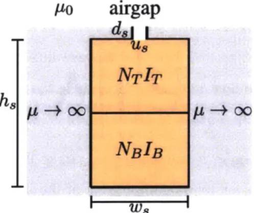
slot shape is considered as shown in 3-2. As shown in the figure, w is the width of the
slot, h the height of the slot, and u and d are the depression (slot opening) width and depth,
respectively. This might not be the most practical slot shape, but can provide a reasonable
approximation to a more realistic slot shape such as the tapered trapezoidal slot which
is widely used in induction machine stators. It will be shown later, that this slot shape
can provide a reasonable approximation to trapezoidal slots, especially for small induction
motors. Furthermore, a tapered, trapezoidal stator slot shape will be considered later for a
more accurate analytical expression for the stator slot leakage inductance.
Po
airgap
8