Artificial Gravity: Changing the Intensity of Coriolis
Cross-Coupled Stimulus with Head-Angle
by
Sophie Adenot
Submitted to the Department of Aeronautics and Astronautics in partial fulfillment of the requirements for the degree of
Master of Science in Aeronautics and Astronautics at the
MASSACHUSETTS INSTITUTE OF TECHNOLOGY
August 2004
@
Massachusetts Institute of Technology 2004. All rights reserved.Author... --...
Department of Aerona ics and Astronautics August 6, 2004
/11
C ertified by ... Accepted by ... MA SSA;CNU Fij, 'Q_; U OF TECHNOLOCYFFR 1
2005
AER
Is
Larence R. YoungApollo Program Pr ssor of stronautics and Professor of Health Science and Technology Thesis Supervisor
...
...
.. ...
\.
...
Jaime eraire Professor of Aer nautics and Astronautics Chair, Committee on Graduate Students
4
3
Artificial Gravity: Changing the Intensity of Coriolis Cross-Coupled Stimulus with Head-Angle
by
Sophie Adenot
Submitted to the Department of Aeronautics and Astronautics on August 6, 2004, in partial fulfillment of the
requirements for the degree of
Master of Science in Aeronautics and Astronautics Abstract
Artificial Gravity (AG) created by high-speed rotation is a promising method for pre-venting the serious deconditioning associated with prolonged exposure to weightlessness. Unfortunately, head-movements in a rotating environment create Coriolis cross-coupled stimuli that introduce problematic vestibular responses. Earlier studies have shown that it is possible to achieve at least partial adaptation to these stimuli, and that side-effects diminish by the end of the training. This thesis seeks to contribute to the understanding of the problem of optimization of and efficiency in AG-training.
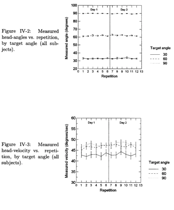
We tested 14 subjects to see if variations of the angle of head-turn (300, 60*, 90*), when performed on a 23 rpm short-radius centrifuge, had an effect on adaptation on VOR gain, on time-constant, and on subjective reports (motion sickness, motion illusion and body-tilt). We found that:
1. The pattern of adaptation is different for the time constant r from that of the
am-plitude of the VOR: higher fractional decreases in r are found at smaller angles, but in peak- and normalized slow-phase velocity, higher fractional decreases are found at higher angles.
2. Small head-angles correspond to small intensity of Coriolis cross-coupled stimulus which leads to less discomfort, i.e. low motion sickness and illusion scores, but also to weaker adaptation.
3. When subjects are already familiar with the AG environment, their VOR amplitudes and time constants are smaller, and show smaller fractional decreases.
4. Subjects feel a(n) (illusory) feet-down tilt after to-nose-up head-turns, but they feel horizontal after to-right-ear-down head-turns.
Thesis Supervisor: Laurence R. Young
Title: Apollo Program Professor of Astronautics and Professor of Health Science and Technology
This work was supported by the National Space Biomedical Research Institute through a cooperative agreement with the National Aeronautics and Space Administration (NCC 9-58) and by a fellowship from the Alumni Graduate Scholarship Fund.
5
Acknowledgements
First I thank MIT and the Aero/Astro department for giving me the opportunity to dis-cover this new world of graduate school in Cambridge, and for the support of the Alumni Graduate Scholarship Fund and the support of the National Space Biomedical Research Institute.
I am very grateful to Jeffrey Hoffman, Dava Newman and Charles Oman and especially to Laurence Young, faculty members of the MVL, for being part of this key step in my studies, in my life. Their example convinced me even more that the sequence: "dream-believe-work hard" can make your initial dreams come to reality. I strongly hope that I will have another opportunity to work with you.
I would like to express special gratitude to Alan Natapoff who, with patience and courage, helped me to improve my scientific writing, to consolidate my data analysis, with-out counting the time spent.
I thank Thomas Jarchow for his ingenious solutions, his practical mind, and his devotion to the AG team. Thank you also to the other members of the AG team: the graduate stu-dents, Jessica Edmonds, Ian Garrick-Bethell, and Sylvain Bruni for being wonderful team mates and to our UROPS Agnieszka Koscielniak, Carlos Pinedo, Benjamin Feinberg and Thomas Walker for being so helpful.
A special thank goes to the MVL lab-mates, thanks to each of you for sharing your good spirit, your humor, your passion for space travel and your talents... a fantastic crew which makes the MVL a pleasant boat in which to navigate one's way through graduate school.
I thank Liz Zotos for whom any administrative difficulty is always replaced by instant solution and smile!
Last, but certainly not least, my thanks go to Papa et Maman, to Laurent, to Michel Viso and to my family -from heart or blood link- who guided me along the way to my dreams, your encouragement has made all this possible.
Contents
List of Acronym s . . . ... . . . . 10
I Introduction 11 II Background 13 A Human adaptation to the AG environment ... ... 13
A.1 The feasability of adaptation ... 13
A.2 The optimization of adaptation ... ... 15
B From stimulus to response: Description of the stimulus . . . . 17
B.1 Single head-movement parameters . . . . 17
B.2 Overall training parameters . . . . 20
B.3 The mathematical equations describing the Coriolis stimulus . . . . 21
C From stimulus to response: Description of the response . . . . 26
C.1 Vestibular physiology and VOR response . . . . 26
C.2 Motion illusion response . . . . 30
C.3 Motion sickness response . . . . 31
D From stimulus to response: The building of a conflict . . . . 36
D.1 Explanation for motion sickness responses . . . . 36
D.2 Explanation for VOR responses: canal and otolith conflict . . . . 42
E Toward a solution to the optimization problem . . . . 44
E.1 An adapted state with an overall minimal response to the CCCS . . 44
E.2 Measuring the efficiency of the training . . . . 45
E.3 Introduction to the experiment conducted . . . . 46
IIIMethods 47 A Hypothesis . . . . 47
B Experimental design and protocol . . . . 47
B .1 D esign . . . .. 47
B .2 Protocol . . . . 48
C Equipment and Measurements . . . . 49
C.1 Centrifuge . . . .. 49 7
CONTENTS
D E
C.2 Eye monitoring . . . . C.3 Head monitoring . . . . C.4 Metrics of subjective experience . . . . Subjects . . . . Data analysis . . . . E.1 From the eye position to the slow-phase velocity E.2 From the SPV to the NSPV . . . ..
E.3 Note on individual subjects . . . .. IV Results
A Head- angle and velocity data . . . B Analysis of eye movement data . . B.1 Time-constant r . . . .
B.2 Peak SPV . . . .
B.3 NSPV . . . .
C Analysis of subjective reports data C.1 Motion sickness . . . . C.2 Illusion . . . . C.3 Body tilt . . . . V Discussion
A Overview of key findings . . . . B Explanation of key findings . . . . B.1 Patterns of adaptation for r and NSPV B.2 The effects of small intensities of CCCS B.3 The effects of prior-exposure to CCCS. B.4 Illusory body-tilt . . . . C
D
Limitations for this experiment and recommendations Im plications . . . . VI Conclusion
APPENDICES:
A Protocol's Checklist B Consent Form
C Dysqualifying medical conditions D Comments about the CSSI test
49 50 51 53 53 53 54 56 57 58 60 62 64 67 70 72 74 76 77 77 77 77 81 83 84 84 86 89 95 95 97 101 103 8
CONTENTS 9
E Interactive Matlab file for data analysis 105
F Other graphs 111
CONTENTS
List of Acronyms
The following acronyms are used: " AG Artificial Gravity
" CCCS Coriolis Cross-Coupled Stimulus " CSSI Coriolis Sickness Susceptibility Index * GIA Gravito-Inertial Acceleration
" GIF Gravito-Inertial Force " HM Head movement " MS Motion Sickness
" MVL Man-Vehicle Laboratory
" (N)SPV (Normalized) Slow-Phase Velocity " VOR Vestibulo-Ocular Reflex
" aVOR angular VOR
" IVOR linear VOR
ISCAN, Matlab, Microsoft, Adobe, Systat, StatXact mentioned in this thesis are trade-marks of the respective companies.
Chapter I
Introduction
Prolonged weightlessness has adverse health effects against which Artificial Gravity rep-resents a potential countermeasure: bone and muscle loss, cardiovascular deconditioning, neurovestibular disturbances [31]:
" Bone loss: Extended missions in weightlessness can provoke the loss of as much as 20 percent of bone mass. The risk of fracture is then significantly increased as well as the possibility of renal stone formation due to calcium mobilization from bone. " Muscle loss: Astronauts on long missions may lose up to 25 percent of their muscle
mass because weightlessness places a reduced load on the leg- and back-muscles used for maintaining posture on Earth.
" Cardiovascular deconditioning during an extended mission reduces cardiac mass which leads to a drop in blood pressure, faintness when standing erect, and reduced exercise capacity.
" Neurovestibular disturbances in weightlessness involve disorientation, motion sickness and a loss of sense of direction for many astronauts. On return, the vestibular organs and the central nervous system must readjust to the presence of a gravity cue, and astronauts may suffer from vertigo, motion sickness and equilibrium problems. These problems lead to significant increases in risk if an emergency egress from the spacecraft is required upon landing. Traditional countermeasures such as exercise, resistive garments, and lower-body negative pressure are insufficient. Artificial Gravity (AG), created by short-radius centrifugation, could complement these by delivering intermittent doses of gravity. The AG-solution attempts to remove the cause of the adverse effects of spaceflight rather than to cure their symptoms (Young
(47],
[49]).The use of short-radius centrifugation, however, introduces problematic vestibular re-sponses. Out-of-plane head-turns on a centrifuge create a disturbing stimulus called the
12 CHAPTER I. INTRODUCTION
Coriolis Cross-Coupled Stimulus (CCCS). These head-movements out of the plane of ro-tation provoke unexpected illusory sensations of motion, inappropriate vestibulo-ocular re-flexes, and motion sickness. The Man-Vehicle Laboratory has recently performed studies with a two-meter Short-Radius Centrifuge (SRC), which find that subjects are capable of adapting their response to minimize these side-effects. The present thesis lies within the scope of research: (1) to understand better how adaptation to the CCCS occurs, and (2) to lay out an efficient training in AG after which astronauts could eventually make completely unrestrained head-movements free from adverse effects.
Chapter II
Background
A
Human adaptation to the AG environment
A.1
The feasability of adaptation
One of the goals of the Artificial Gravity (AG) research project is to optimize adaptation
to the Coriolis Cross Coupled Stimulus (CCCS). To do so, one needs first to define adapta-tion. According to the Oxford Dictionary, "adaptation is the process of modifying a thing so as to suit new conditions". In the biology section of the same dictionary, "adaptation is an organic modification by which an organism or species becomes adapted to its environ-ment". In both statements, adaptation requires repeated exposure to a new environment, and a plastic system able to change its mechanical/wiring properties to give new responses. The new environment in our case is that of a short radius centrifuge, rotating at 23 rpm, in which a person riding on it does head movements. The system being adapted is mainly the human vestibular system. The adaptability of the human vestibular system has been known for a long time, as detailed in the following paragraphs.
The plasticity of the human vestibular system
Several clues enable us to conclude that the vestibular system is indeed plastic. One of them is its adaptability to weightlessness: an extreme environment which implies the loss of gravity cues on graviceptors, especially the otoliths. This loss of "tonic pull" (as refered to by Merfeld [25]) causes the vestibular system to change over the course of ap-proximately three days (Shelhamer and Zee [43]) after which motion sickness and spatial disorientation symptoms of the astronauts are less substantial. A re-adaptation is needed on return to Earth too. After a long term spaceflight, the response of the vestibular sys-tem is no longer appropriate to a full gravity environment, and leads to oscillopsia and vertigo. The astronauts may suffer these symptoms for up to two to three weeks.
CHAPTER H. BACKGROUND
ing the re-adaptation process, the brain re-learns to interpret the otolith signal for both tilt and translation cues [25]. A second example which illustrates the plasticity of the vestibular system is the vestibulo-ocular adaptation which occurs while wearing reversing prisms (Gonshor and Melvill-Jones [16]). The eye reflexes driven by the vestibular system are significantly modified in order to achieve image stabilization during head-movements when subjects wear magnifying or minifying lenses, or prisms that rotate or displace the image. The characteristics of vestibulo-ocular reflexes (VOR) are altered: gain, phase, and even a cross-axis transfer of eye movements can occur. A third example of plasticity of the vestibular system is the adaptive compensatory process that takes place in case of a vestibular asymmetry. Hemi-labyrinthectomized cats were able to recover and to eliminate,
after a few weeks, the spontaneous nystagmus and asymmetrical VOR (Young [48]).
Habituation vs. adaptation
Adaptation is distinguished from habituation. The Oxford dictionary states: habitua-tion is "the diminishing of a response to a frequently repeated stimulus". Habituahabitua-tion can be compared to getting used to a noise or smell, so that after repetition, the habituated body doesn't perceive the stimulus to be as strong as during the first exposure (Brown [5]). Adaptation, on the other hand, involves purposeful or at least useful modifications of the system control characteristics (Young [48]). Adaptation often leads to a significantly differ-ent type or intensity of response.
Context-Specific Dual Adaptation
Ideally, the goal of the Artificial Gravity research program would be to find an Earth-based training that leads to context-specific dual adaptation (CSDA). Such training should enable astronauts to switch between rotating and non-rotating environments and be able to move their head freely without the common discomforts of CCCS: motion illusions and motion sickness. Dual adaptation has been shown in the Pensacola slow rotating room (Parker [36]), so there is hope that it is also possible to acquire CSDA for intermittent SRC. As mentioned by Shelhamer [43], CSDA refers to the ability of an organism to:
"1) Maintain two different adapted states for a behavioral response (such as two different saccade or vestibulo-ocular reflex (VOR) gains)
2) Have each state associated with a specific context state (such as g-level), and 3) Switch between the adapted states immediately upon a change in context state (without the need to adapt anew upon each transition -in a feed-forward and not a feed-back manner)."
In the present case, artificial gravity would be the context cue to switch between the two dif-ferent adapted states. Two general issues remain concerning the adequacy of ground-based
A. HUMAN ADAPTATION TO THE AG ENVIRONMENT 15
AG training for reaching CSDA. First, we don't know whether reaching CSDA is possi-ble. Second, we don't know whether the training would be transferable to a microgravity environment1.
Assuming that adaptation is necessary for CCCS in weightlessness, we would like to know if the constant Earth-gravity cue is also a context-specific cue necessary both for the adaptation and for switching between states. How then could the Earth-adaptated state be transferable to a weightlessness-adapted state? We wish to understand if, once we have adapted a subject on Earth to minimize, e.g., motion sickness, the same benefits will be felt by the subject in space. These research themes have to be fully investigated before a long term space flight to another planetary body is undertaken. In such a flight, the astronauts would have to be able to switch rapidly in order to be functional in several gravitational environments (1g; AG and Og for the interplanetary transfer; 0.38g for Mars).
Adaptation to the CCCS
Several studies have been performed in the MIT short-radius centrifuge to show that adaptation to the CCCS at 23 rpm is possible. Sienko [44 and Lyne [24] found that adaptation occurred over two days and was partially retained over five days. This provides evidence of partial acquisition and retention of adaptation. Brown [5] found that nearly all response parameters, including motion sickness and illusory tilt, decreased over the experiment, and that visual input is needed for a more efficient adaptation of eye movements.
Garrick-Bethell [14] found adaptation to pitch movements in the reduction in time-constant and illusory-motion scores.
A.2 The optimization of adaptation
Section A.1 enabled us to give a positive answer to this question: Is adaptation to the CCCS possible? The next step is to search for ways the adaptation process can be optimized in order to have rapid and efficient astronaut-training.
This optimization problem can narrow itself to a minimization problem, and can be described in the language of optimization theory by:
min R(x), with x E S,
where R is the response function, x is a vector of stimulus parameters (Xi, ..., X), and S is the set of all feasible Coriolis cross-coupled stimuli that the subject can experience2
The response function can be defined as a two-dimension vector containing the phys-iological responses (as measured, e.g. by eye-movements parameters) and the subjective
'For a more detailed discussion about this issue, refer to section B.1
2
In optimization theory, R is called the objective function, x the choice variable, and S the constraint set or opportunity set.
CHAPTER H. BACKGROUND
responses (as measured, e.g. by motion sickness scores):
R(x) Physiological Response PR(x) Subjective Response SR(x)
The vector of stimulus parameters includes, for example, the velocity of the centrifuge, the type of head movements performed (pitch, roll or yaw), the duration of the training, etc. Each parameter is limited in amplitude: The angle of head-turns, e.g., is limited to 90* in each quadrant. These limits are specified by the boundaries of the set S.
The objective is to find an training with a set of stimulus parameters (Xi, ..., Xz) that would lead to an adapted state with minimum physiological and subjective responses.
The next sections of the background chapter includes:
" a description of the stimulus parameters (xi, ..., xn) and the set S which contains
them (section B),
" a description of the response parameters (section C),
" an attempted description of the functions that associate the stimulus and the response parameters (section D),
* a discussion of the efficiency of the adaptation process (section E). 16
B. FROM STIMULUS TO RESPONSE: DESCRIPTION OF THE STIMULUS 17
B
From stimulus to response: Description of the stimulus
The following paragraphs in this section give a detailed description of the parameters that play a role in the determination of the Coriolis Cross-Coupled Stimulus (CCCS): both single head-movements and more general training parameters are described.
B.1 Single head-movement parameters
Head Movements (HMs) during centrifugation drive semicircular canal inputs that have no counterpart in ordinary terrestrial experience. These inputs come from Coriolis coupling between head- and centrifuge- rotation. Several parameters contribute to cross-coupling effects. The present section will describe the parameters and the equations of motion that figure the stimulus. Table II.1 shows a list of parameters needed to estimate the intensity of a CCCS for single head movements. They do not play equal roles. The following paragraphs describe each of them and their influence as seen in the literature.
HM parameters Centrifuge parameters
type velocity
angle acceleration
velocity
Other parameters position and orientation of head / axis of rotation visual feedback
gravity environment
other (proprioceptive, auditory, etc.)
Table II.1: List of Head Movement (HM) parameters for evaluation of the Coriolis Cross-Coupled Stimulus (CCCS) intensity
Type of Head Movement (HM):
" Description: We define the type of HM as pitch, roll or yaw head-turns in the frame-of-reference of the head, as shown on figure II-1. Only the HMs that take the head out of the plane of rotation create the CCCS. For example, when lying supine on the rotating centrifuge, only yaw and pitch HM are provocative. (On a Barany chair, only pitch and roll HM are provocative). Positive (sense of) head rotation is defined by the right-hand rule. For yaw head movements on the centrifuge, positive movements are from "right-ear-down" to "nose-up".
" Literature review: Garrick-Bethell [14] investigated the possible adaptation to pitch as a result of training in the yaw plane. (None was found.) Garrick-Bethell found that the pitch HM VOR amplitude shows a greater decrement than the yaw HM VOR does over the same number of trials. Tiliket [46] also found no evidence of U
CHAPTER H. BACKGROUND
transfer of adaptation across planes, from a vertical rotating chair-position to a head-tilted position. This suggests that the training of astronauts will have to include a separate program of adaptation for each plane, since they need to adapt to motion in all planes if they are to function normally while rotating. Guedry [19] observed that little transfer of adaptation occurred between HM in different quadrants of the same plane. Two studies on the MVL SRC, however, have shown successful transfer of adaptation between quadrants
[13],
[44].Convention for head-axes: Physical variables are represented by three-dimensional
vec-tors in a righthanded orthogonal head-fixed frame of reference (x, y, z) where the x-, y-, and z-axes are the naso-occipital, interaural and rostrocaudal axes with positive values forward, to the left, and to the top of the head, respectively. For rotation, the x-, y-, and z-axes represent roll, pitch, and yaw rotations with positive values clockwise, downward, and to the left, respectively, as shown on figure II-1.
/ Z head axis
Figure II-1: Head-axes and naming conventions for types of Head
Move-ments (pitch, roll, yaw). Y hdis
Positive (sense of) head
X head axis'6
rotation is defined by the Rol
right-hand rule.
Angle of HM (in deg):
" Description: The angle of HM is the number of degrees through which the subject rotated his/her head. Obviously, this angle is smaller than 900 for one quadrant. " Literature review: I have found no published study of this parameter. It is one of
the goals of the present thesis to investigate this question. Guedry and Benson [18] did mention that large angles HM (0) are more disorienting and nauseogenic than small angles. They explained it by noting that the angular velocity stimulus for the semi-circular canal is we sin0. Section B.3 will discuss the equations that support Guedry and Benson's argument.
Velocity of HM (in '/sec):
" Description: The velocity of HM measures of how fast the subject rotates his/her head.
" Literature review: I have found no published study of this parameter. The equations of motion (section B.3) show that this parameter appears only transiently when the 18
B. FROM STIMULUS TO RESPONSE: DESCRIPTION OF THE STIMULUS
head is moved: the angular acceleration term, in which the velocity of HM appears, is zero when the head movement stops. This suggests that the influence of the velocity of HM is of lower order compared to that of the angle of HM or to the velocity of the centrifuge.
Velocity of the centrifuge (in */sec or rpm):
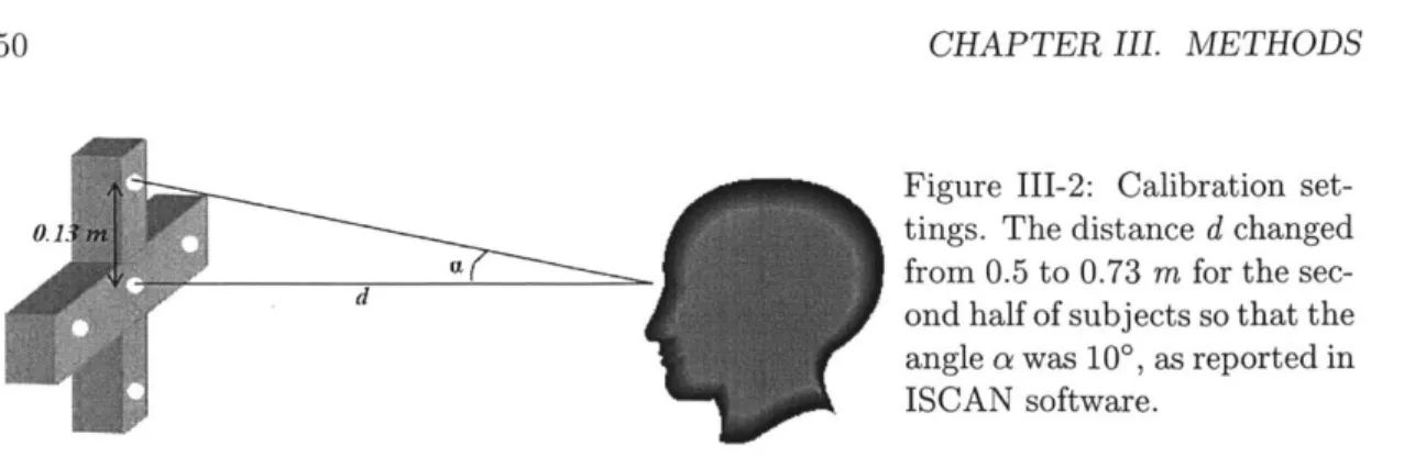
" Description: The velocity of the centrifuge determines the magnitude of artificial gravity at the heart or feet. The formula is: wc x where we is the angular velocity of the centrifuge, g is the acceleration of gravity (9.81 m/sec2), x is the
target value of acceleration (in g) that the subject is to experience at a distance R (in meters) from the center of rotation. For almost all the experiments in the MVL,
oc = 138*/sec (23rpm), which is obtained with x = 1g at the feet (R = 1.7m). Using the SRC as a countermeasure for physiological effects of spaceflight creates a gravity gradient between the head and the feet which is 1 gravity unit per body length, i.e.,
g/R. On the current MVL centrifuge, the gravity gradient is 1 since the head is at
the center of rotation.
" Literature review: we drives the intensity of the CCCS. The nauseogenic angular
velocity stimulus for the SCC is wc sin 0. This parameter, together with the radius of the centrifuge, determines the dosage of AG for the body, which is the bone and muscle deconditioning countermeasure. Miller and Graybiel [27] introduced the concept of individually-selected centrifuge velocity. Their goal was to take into account the inter-subject differences in MS susceptibility: highly susceptible subjects are exposed to CCCS with low centrifuge velocity, whereas the more robust could reach a velocity as high as 30 rpm (see section C.3). Another line of research studies of the effect of we in incremental adaptation, protocol in which the subject is exposed to increasingly nauseogenic Coriolis stimuli.
Acceleration of the centrifuge (in 0/sec2):
" Description: In the experiments being run in the MVL, the angular velocity is main-tained constant (often at 23 rpm) so that the tangential angular acceleration is zero. " Literature review: Guedry and Benson [18] found that HM done in the accelerating phases (increasing centrifuge velocity) are less provocative than these at constant centrifuge speed, which are in turn less provocative than at decreasing centrifuge speed.
Position of the head / center of rotation:
* Description: In both the MVL centrifuge- and Barany chair- configurations, the center the head (between the two ears) is close to (or on) the axis of rotation. To define the
CHAPTER II. BACKGROUND
position of the head on the centrifuge, we need: 1/ a distance from the axis of rotation and 2/ an orientation of the head with respect to the rotation of the centrifuge (this latter contributes importantly to the signal sensed by the vestibular organs, especially the otoliths). In long-radius centrifuges, the head is far from the center of rotation, and the effects are very different.
* Literature review: I have found no published study of this parameter. Visual feedback:
" Description: The visual feedback can be either "dark" (with blindfolds and black canopy around the centrifuge), "stable" (with a centrifuge fixed visual field) or "ex-ternal" (with a full view of the room). The terms are taken from Brown's study [5] done in the MVL.
" Literature review: Brown finds that there is a significant effect of these three visual conditions on eye movement parameters. Subjective measurements such as motion sickness and illusory self motion, however, were not significantly influenced by the type of visual input.
Gravity environment (in m/sec2):
" Description: This is the magnitude of the gravity field in which the experiment is performed. Obviously, in the MVL experiments, the magnitude of gravity is constant and equal to 9.81 m/sec2.
" Literature review: Does the CCCS provoke the same discomfort in weightlessness as on Earth? Some experiments conducted aboard Skylab (Graybiel, Miller and Homick [17]) and during parabolic flights (Lackner and Graybiel [231) suggest that motion sickness and neurovestibular consequences are either significantly reduced or eliminated in weightlessness: the major sensory conflict that drives these symptoms disappears in the absence of gravity cues, and this removes conflicting gravito-inertial signals on the otolith organs. Other sets of results support this explanation including the absence of motion sickness or "nystagmus dumping" during post-rotatory head pitch on SLS-1 and SLS-2 (Oman and Balkwill [33]; Oman, Pouliot and Natapoff [341),
in parabolic flight (DiZio and Lackner [10]), and during short-radius centrifugation on Neurolab (Moore [29]).
B.2 Overall training parameters
Section B.1 listed the possible parameters that can be varied for a single head-movement on the centrifuge. The training that we want to optimize, however, will be made of a se-quence of head-turns, repeated over days or weeks. So more parameters need to be added 20
B. FROM STIMULUS TO RESPONSE: DESCRIPTION OF THE STIMULUS
to properly define the CCCS training to help the process of optimization.
Within one exposure, i.e., one session of the training, the following parameters can be varied:
" number of HMs,
" frequency of HMs, i.e. how long subjects rest between to consecutive head-turns (Generally, at least 20 seconds is required to allow both the decay of VOR and the time to report subjective experience).
These two parameters together give the duration of exposure, i.e. the time-length of one training-session. The consent form in the MVL experiment specifies that the time of cen-trifugation should not exceed one hour.
Finally, for the whole training, the following parameters can be varied: " number of exposures,
" frequency of exposures, i.e. the time between two sessions of AG-training.
B.3 The mathematical equations describing the Coriolis stimulus
Among the parameters listed earlier to describe the CCCS training, very few of them determine the actual angular velocity stimulus to the Semi-Circular Canals (SCC). This section details the mathematical equations describing the CCCS to estimate the intensity of the angular velocity stimulus applied to the SCC. This paragraph focuses on angular velocity to the the semi-circular canals for pitch and yaw head movements, with the help
of Euler parameters.
a - Description of the movements
Centrifuge
/
EarthThe Earth-fixed coordinate frame is (V, yo, V), and the centrifuge-fixed coordinate frame is (V, pi, V), initially oriented as suggested on figure II-2. The centers 00 and 01 of the earth- and centrifuge-fixed coordinate frames, respectively, are the same.
The vertical gravity vector is: I = -IgI.
The movement of the centrifuge is described by: -T/o = -wo, and the angle that describes this rotation is
#,
as suggested on figure II-3. The notation we instead of Wi/o will be kept, for better clarity3.3
Here, wc = 23 rpm. The (-) sign indicates the clockwise rotation of the SRC in the MVL, clockwise as
seen from above
CHAPTER II. BACKGROUND
00=01=
102
Figure 11-2: Conventions
for vector orientation. 'i eenaJge
yo
Earth frame
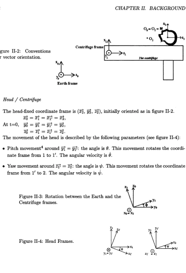
Head / Centrifuge
The head-fixed coordinate frame is (Y, pi, 2), initially oriented as in figure 11-2.
4O = YXI = Y 1" =Y2,
O = TZ' = V1lI = 2
.-The movement of the head is described by the following parameters (see figure 11-4):
* Pitch movement4 around pl = pj: the angle is 9. This movement rotates the coordi-nate frame from 1 to 1'. The angular velocity is 9.
" Yaw movement around z-i = Y: the angle is st. This movement rotates the coordinate
frame from 1' to 2. The angular velocity is
/.
ZI
~
Figure 11-3: Rotation between the Earth and the Centrifuge frames.
Zj' Y2
Figure 11-4: Head Frames. x2
y1 - yr xr zi -z
4The coordinate frame (1,, z -i) is a temporary frame used for decomposition of the 2 head movements
(pitch-yaw). 22
B. FROM STIMULUS TO RESPONSE: DESCRIPTION OF THE STIMULUS 23
Convention for the notations:
The symbol -ji7 represents the angular velocity of a body moving in frame i as seen in frame j. Correspondingly the angular acceleration Z{j,; is that of a body moving in frame i as seen in frame j. The symbol [Vector]F. means that the vector is expressed in Fi coordinate frame i.
The angular velocity of the head with respect to the centrifuge frame is:
V2 + 691j
= Yaw
+
PitchThe semi-circular canals sense -j 2 , the angular velocity with respect to the inertial frame, expressed in the head coordinate frame F2. To express the vector 0U71 in the frame
F2, we need to find [Yii]F2.
[ F2 [ F2 F
To express the vector 02g in the frame F2, we need to find [W]F2, and
[YF
2, thanks to the equations:[yi,]F2 = R1'to2 x (']F,
[YW]F2 = R1to2 -Ritoi' x [r]F1
where R 1'to2 is the matrix of rotation from the coordinate frame 1' to 2.
b - Expression of the angular velocity vectors
General Pitch-Yaw head movements on the centrifuge
The angular velocity is, in the head coordinate frame F2, i.e. (V, V2, 2):
0 sin ' - we cos 0 cos
1
0F2 = cos V) + wc cos 0 sin 0
S-we sin 0
Whereas in the inertial coordinate frame F, i.e. (V, yo, V), it is:
-we + 4 sin
1
[ F2/o =
[
cos - cos sinJ
0sin
f
+ $ Cos 0 Cos#Note: The cross product Whead x
We
(here, whead is4
ord)
appears only when we write down the angular acceleration (see the following section).24 CHAPTER II. BACKGROUND
Single pitch head movement on the centrifuge
For a single pitch movement, we set the yaw parameters (0 and '/2) to 0. The angular velocity is, in the coordinate frame of F2, i.e. (V, Y, Y):
-co Cos 0
SF2 (11.1)
L-We sin 0
Whereas in the coordinate frame of F0, i.e. (V, so, T), it is:
-Woc 02]Fo Cos
0 sin p
We can, therefore, write the angular acceleration, assuming We is constant as: 0
d--0] Fo .Wc sin + §cos
1
-we cos
#
+ § sinJ
Which gives, after applying the appropriate rotation matrices, the angular acceleration in the frame F2
E
w wsin O[20]F2
-9we cos 0
Single yaw head movement on the centrifuge
For a single yaw movement, we only set the pitch parameters (0 and 9) to 0 in the general equations.
The angular velocity in the head coordinate frame F2 is:
-co Cos
[9]F2 [c sin
j
(11.2)Wheras in the inertial coordinate frame F0, it is:
[0-0 Fo
[
sin]
B. FROM STIMULUS TO RESPONSE: DESCRIPTION OF THE STIMULUS
We can, therefore, write the angular acceleration, assuming we is constant as: 0
[62/0+ [Fo wc cos# - sin #
we sinq# +4@ cos
#
Which gives, after applying the appropriate rotation matrices, the angular acceleration in the frame F2
[
wesin@ 1[U0]F2 Wc cos4V
The choice of a name for CCCS
This CCCS has a tumultuous naming-history. It has been called the Coriolis stimulus, the Cross-Coupling stimulus or the Coriolis Cross-Coupling stimulus, and new papers using a new denomination often criticized and argued against the old term. Guedry [22] argues that all the names are appropriate. The term Coriolis Stimulus was first used by Schubert in 1932 and has been unnecessarily questioned in the 1960s. Coriolis acceleration is a linear acceleration and the canals are stimulated by an inertial torque whose direction and magnitude can be directly derived by integrating the components of the Coriolis acceleration vectors that act on the canal walls at each point around the endolymph ring The equations are well described by Peters [37]. The name cross-coupling is also appropriate because the stimulus to the canals can be derived from calculations of changes in angular momentum or from analyses of Cross-Coupling effects. That is why the name Coriolis Cross-Coupling stimulus has been adopted by many researchers. This name is not perfect either, because when the head movement is made during initial acceleration on the centrifuge, the Coriolis and Cross-Coupling effects occur, but the illusion and nausea with which this stimulus is generally associated do not.
History has given reason to the name Coriolis Cross-Coupling Stimulus (CCCS), so it is preserved here. Nevertheless, we may suggest other non-perfect names: Centrifuge Stimulus, MOC5 Stimulus (though it does not create mock nausea), MAGIC' Stimulus. We will agree to call it CCCS, which at least provokes curiosity.
5
Moving On a Centrifuge
6
Moving in Artificial Gravity Induced by Centrifugation
26 CHAPTER II. BACKGROUND
C
From stimulus to response: Description of the response
The response parameters analyzed were: eye-movement responses, motion sickness and illusion responses, on which the paragraphs below give background information.
C.1 Vestibular physiology and VOR response Vestibular physiology
Head- and body-movements create angular and linear accelerations that the vestibular system senses. Vestibular inputs, combined with those of visual and somatosensory systems, interact to elicit eye-, head-, and body-movements that stabilize gaze and maintain posture in three-dimensional space. The vestibular organs are embedded in the petrous portion of the temporal bone. They are composed of the Semi-Circular Canals (SCC) which detect angular acceleration, and of the otolith organs, which detect linear acceleration.
The semi-circular canals
The SCC are made of three approximately orthogonal canals, filled with a viscous fluid called endolymph. The canals are enlarged at their ends called, at the ampulla. Fluid flow from the ducts into the ampulla causes deflection of the cupula (a gelatinous membrane located within the ampulla of each semicircular canal that completely seals the canal). This displacement of the cupula modulates the firing rate of its hair cells, which transmit signals along the vestibular nerve and encode changes in the rate and direction of rotation of the head in the three spatial planes, corresponding to the planes of the canals.
The canal fluid mechanics is described by an overdamped torsion pendulum model which first arose from the work of Steinhausen in 1931 [45], and was updated by Goldberg and Fernandez [15] to match the measurements more accurately. It is represented in the Laplace domain by the transfer function:
-~ (s+A/r)( s+r/H) 1+TA s
a is the angular acceleration input and ( is the angular displacement of the cupula. II represents the damping frictional drag of the endolymph fluid, A is the spring constant of the cupular restoring force and
E
is the moment of inertia of the toroidal fluid ring. The time-constants r1 = H/A and 72 =e/II
are, respectively, the dominant and short time constant of the cupula; rA corresponds to an adaptation process. Their values were deter-mined by Goldberg and Fernandez [15] as: Ti = 5.7, T2 = 0.003 and rA = 80, seconds.The SCC sense angular acceleration, but the motoneurons code the position (not the ac-celeration) of the eye. Consequently, two integrations take place to convert head-acceleration
C. FROM STIMULUS TO RESPONSE: DESCRIPTION OF THE RESPONSE 27
to eye-position: One is done mechanically at the hair cell level so that the canal afferents in the vestibular nerve closely follow the angular velocity of the head; The other is done in the brain stem, close to the motor nuclei. The time constant of the velocity-position integrator is about 30 seconds; its value is under cerebrellar control [42].
The otolith organs
The otolith organs are the primary means by which we sense linear acceleration of the head and the orientation of the head with respect to Earth's gravity. The otolith organs include two sac-like structures called the utricle and the saccule, which contain a small sensory area of approximately 2 mm in diameter known as a macula, which include hair cells. The cilia which emerge from these hair cells are embedded in a gelatinous matrix called the otolithic membrane. That membrane contains small piles of calcium carbonate crystals
(CaCO3), called otoconia, which have greater specific gravity than the surrounding tissue.
Forces due to linear acceleration cause the cilia to bend so that the signal is transmitted to the vestibular nerve.
The dynamics of the otolith can be modelled by the transfer function:
I= 1 - with rr2M-- (B)
( is the relative displacement of the otoconia and macula, is the linear acceleration of space relative to space, M represents the inertia of the otoliths, and B and K represent the viscous and spring coefficients of the displacement of the otoconia.
VOR response
The primary function of eye-movements is to keep the foveal image stable and on tar-get. They can prevent the retinal image from moving when the observer or the object being observed moves. Two kinds of eye-stabilizing movements are therefore required: one to compensate for movements of visual objects and the other to compensate for movements of the head. Any rhythmic motion of the eyes is called nystagmus.
The optokinetic nystagmus compensates for movements of the visual scenes relative to a person. It is driven by motion of the retinal image.
The vestibulo-ocular reflex (vestibular nystagmus) compensates for head movement. It is driven mainly by stimuli from the vestibular end-organs: the otoliths and the semi-circular canals rather than the eyes. When a subject is rotated clockwise, the eyes move in a counter clockwise direction to stabilize the retinal image: this eye movement is called a slow phase nystagmus. After the eyes have rotated a certain distance, they quickly return to begin an-other compensatory movement. This return sweep, called fast phase, can reach 800 deg/sec or more (Howard [21]). The function of the slow phase in the vestibular nystagmus is to
CHAPTER H. BACKGROUND
stabilize the retinal image, and the function of the fast phase is to reposition the eye. These two compensatory reflexes (VOR and optokinetic nystagmus) are primitive and controlled almost entirely by subcortical centers. There are two types of VOR: the angular VOR (aVOR), driven mainly by inputs from the SCC, and the linear VOR (lVOR), driven mainly by inputs from the otoliths organs.
The VOR is a compensatory, plastic behavior. For the aVOR, the gain is defined as the ratio of induced slow-phase eye-velocity divided by the stimulus head-velocity. The dominant time-constant is defined as the time over which the eye-velocity response to a step of head-velocity decays to 63% of its peak value. The dynamics of aVOR are, however, better described with two times constants:
" the peripheral time-constant, associated with the decay in the eighth nerve activity, which depends on cupula dynamics and hair cell transduction. Since it is fixed by mechanical properties, its adaptation capability is limited.
" the central time-constant, also called the time-constant of the velocity storage integra-tor, longer than the peripheral one. Its - plastic - value depends on previous motion experience and is decreased when exposure to the stimulus is repeated.
This velocity storage integrator is modeled as a leaky integrator that stores activity from the eighth nerve related to head-velocity and outputs a velocity command to produce slow-phase eye-velocity. It is separate from the integrative neural network that produces velocity-to-position integration mentionned earlier [20].
VOR during head movements on the centrifuge
The background section B.3 described the equations of motion of the stimulus encoun-tered during head turns on the centrifuge. These equations can predict which VOR -vertical, horizontal or torsional- is observed when subjects experience the CCCS.
For a single yaw head movement of amplitude 0 and velocity
4,
the angular velocity which stimulates the SCC during the head-turn - as expressed in the head coordinate frame (V, 2, 2) - was detailed in equation 11.2 as:-w cos V
The SCC sense the change in angular velocity, so if a head-turn is made from V51 to 02,
the change in angular velocity is (01 is set to zero in the right member of the equation, as it is for HM starting from "nose-up" position):
C. FROM STIMULUS TO RESPONSE: DESCRIPTION OF THE RESPONSE
-[ c(cos 02 - cos 01) - (COS 02 -1)
F2 = Wc(sin V2 - sin 21) =
w
sin 20 J0
This equation predicts that:
" There is a transient angular velocity stimulus to the yaw plane (T), of amplitude
(which lasts only as long as the head is moving, i.e. so long as b is different than 0) e There is a steady-state angular velocity stimulus to the roll and pitch planes (Y
and y) of respective amplitudes: -wc(cos4'2 - cosV1i) and wc(sin@'2 - sin /i). This stimulus will be present not only during the head turn, but also after it, provided that the angle of head displacement is not 0, i.e. 02 5 01.
This steady-state stimulus leads to a VOR response that can be seen measured in prac-tice. The stimulus to the pitch plane leads to vertical VOR which is measured thanks to the ISCAN system described further on. The stimulus to the roll plane leads to torsional VOR, which our current version of ISCAN cannot detect. This torsional VOR is subtle, hard to detect, and not always easy to observe in all subjects.
Equation 11.2 also predicts the direction of the vertical VOR slow phase velocity: the amplitude for the pitch plane is we sin@0 along the V axis. In a non-rotating environment, this stimulus would be equivalent to a pitch head turn downward (to chin down) of the same amplitude, and would lead to an upward slow phase velocity (of negative amplitude). In practice, this is exactly what is observed. For movements from right-ear-down to nose-up
(positive head turn about T), the SPV measured has a negative sign.
An analogous analysis could be made for pitch head-movements, leading to horizontal and torsional VOR. The amplitude of the stimulus is given by equation II.1.
Note that the equations are written in the head coordinate frame. The previous para-graph always mentioned the head planes, as opposed to the canal planes which are different. Because the eye movements are recorded in the head coordinate frame, the stimulus was
also described in the head coordinate frame.
Normalizing the VOR response to the stimulus: the NSPV
As described earlier, the angular velocity stimulus of a yaw HM of angle V) is we sin ) along the head-pitch axis y. This provokes a vertical VOR whose peak amplitude of slow phase velocity, A, is normalized with respect to the amplitude of the stimulus:
NSPV = Response Amplitude _ A
Stimulus Amplitude - we sinp V
CHAPTER II. BACKGROUND
Such a normalized parameter assumes that head turns on the centrifuge can be approxi-mated by an instantaneous velocity step change. It does not take into account the stimulus
duration (the transient acceleration component of a head turn).
We expect the NSPV values to be smaller than 0.7, on average. The reason is that the gain of the angular VOR in normal humans during rotation in the dark - on a Barany chair, without head movements - generally lies between 0.5 and 0.7 (Cohen and Raphan, [20]).
This value seems low: the eye velocity in the head coordinate frame should be close to that of a space-fixed target, which would lead to a gain close to 1. Generally, active head-rotation, rotation in the light, and visual input enhances the values of the angular VOR gain. In our experiments, all head-turns are performed in the dark, reason why we expect the average of NSPV to be lower than 0.7.
C.2 Motion illusion response
Head movements on the centrifuge elicit VOR and transient illusory sensation - and for the same reason. Although they are referred to as illusory, these sensations result from a true stimulation of the SCC. During constant velocity centrifugation, the body's response to the stimulus is appropriate - it is precisely the response an accelerometer would give if it went through a "leaky integrator". During a yaw head movement, the dominant illusion is indeed a motion in the pitch plane.
C. FROM STIMULUS TO RESPONSE: DESCRIPTION OF THE RESPONSE
C.3 Motion sickness response
a - Introduction to motion sickness
As given by Reason and Brand [41], and Benson [12],
Definition 1 Motion Sickness is a condition characterized primarily by pallor, cold
sweat-ing, nausea and vomiting that follows upon the perception of certain kinds of real or apparent motion.
Despite its name, Motion Sickness (MS) is neither a sickness nor a disease. It is a normal reaction of the human body to a new environment (which is not necessarily in movement).
MS is debilitating because it induces epigastric discomfort and nausea. Meanwhile, other
symptoms appear: facial or circumoral pallor -around the mouth-, or cold sweat followed
by increased salivation, sensation of bodily warmth, or lightheadedness. If exposure to the
stimulus continues, nausea increases in intensity and vomiting may occur.
In Space, 70 % of astronauts experience MS during the first days of spaceflight. They generally adapt after 2 to 3 days. MS is debilitating, and has an adverse effect on perfor-mance. AG can serve as a countermeasure against deconditioning, therefore, only if it is not nauseogenic, nor it has after effects.
AG sessions should not interfere in any way with vestibular adaptation to microgravity.
It is not obvious that this condition can be fulfilled easily: The French astronaut Jean-Loup
Chrdtien (personal communication to Laurence R. Young) reported that he felt MS only
after he had been on the ground-based centrifuge in the Russian space center. During his training as a fighter pilot and his first space flight with the US, however, he did not feel any symptoms. His report shows that an AG session can be provocative beyond the first exposure, and interfere with "immunity" acquired in earlier provocative situations.
b - A way to evaluate motion sickness
The CSSI test
The Coriolis Sickness Susceptibility Index (CSSI) test7 was introduced by Miller and Graybiel [27] to quantify Coriolis motion sickness. During the test, the subject sits on a Barany chair rotating at an individually pre-selected constant velocity and performs head movements within a standardized pattern as shown on figure II-5(a). To diagnose MS, a simple scoring criterion is used according to the table shown in figure II-5(b). The endpoint of the test is reached when symptoms reach the level severe malaise (M III). The velocity of rotation of the chair is determined according to the results of the Motion Experience Questionnaire (MEQ). Its questions evaluate the average level of relevant prior experience
7
to be pronounced "sissy" (with the French translation: poule mouillie)
CHAPTER II BACKGROUND
UPUISIT MSSITOi
1/5
oieqg m ae.ed fteceme fat Makle e, Saqu ef
H.W MmssVs To aM som Tilt Pslanss Iwessq 5 eDia# cOsh"eW ten
(a) Head-movement procedure
Diognostic Categorization of Different Levels of Severity of Acute Motion Slckness
Pathognomonic Major Minor Minimal AQS Category 16 points 8 points 4 points po ts I pint
Nausea syndrome Vomiting or retching Nauseall, IlI
Skin Pallor III
Cold sweating III
Increased salivation Ill
Drowsiness Il Nausea I Pallor 1I II 11 Epigastric discomfort Pallor I cp awareness Flushintlsssective warmth V Pain Headache > 11
Central nervous Dizziness
system Eyes closed > 11
Eyes open III
Severe Malaise
(M Ill) 8 - 15 points
Levels of Severity Identified by Total Points Scored
Moderate Malaise A Moderate Malaise 8
(M IIA) (M 1II) 5 - 7 points 3 - 4 points Slight Malaise (M 1) 1 - 2 points 32 Frank Sickness (S) 16 points
*AOS -Additional qualifying symptoms. + If - severe or marked, II - moderate, I -slight.
(b) MS scores criteria
C. FROM STIMULUS TO RESPONSE: DESCRIPTION OF THE RESPONSE
(X) and intensity of symptoms (S) for several motion environment categories. It tries to evaluate a subject's susceptibility in advance based on his/her individual history of MS. The CSSI score expresses MS susceptibility to CCCS on a scale 0-100:
CSSI = E x N
N is the number of head movements required to elicit M III; E - the stress factor - is
a quasi-square law dependent on the velocity V of the chair8. This implies that as chair-velocity increases (which means the individual was found to be less susceptible to MS), the increase in E (AE) is larger. In other words, if the subject is less susceptible, the greater increase in E makes it more likely that the CSSI score will be higher. Thus, having a flexi-ble self-selected chair-velocity enaflexi-bles to accomodate a large range of subject-susceptibility. That preselection, however, complicates the analysis since each subject encounters a differ-ent level of intensity of stimulus.
The challenge of evaluating MS scores
To carry out this program, researchers must measure subjective MS symptoms, such as stomach discomfort. Oman, Rague and Rege [35] describe the Pensacola Motion Sickness Scoring System similar to that in [27]. The observer and subject have to grade the sub-jective intensity of eight different classes of symptoms (nausea, temperature, pallor, sweat, salivation, drowsiness, headache and dizziness). The symptoms are assigned a numerical weighted score (1=slight, 2=moderate, 3=severe) and summed to obtain an overall severity level. The severity levels are: slight (1-2), moderate B (3-4), moderate A (5-7), and severe malaise (8-15), and frank sickness (>16).
The recent papers of the MVL-AG research group use a 0-20 scale similar to the Well-Being Ratings described by Reason and Brand [41] (0="I feel fine", 20="I'm about to vomit"). This is more convenient than the Pensacola questionnaire system.
Obviously MS measurement leads to inaccuracies and high inter-subject variability. This makes it worthwhile to seek a more accurately measurable phenomenon, related to MS. One has proven to be easily and precisely measurable, and closely related to MS status. Dai et al
[71
show that the time-constants for horizontal and vertical aVOR are closely - and inversely - related to the maximum number of head turns and therefore to the severity of motion sickness. The function that relates the VOR time-constants to the number of head turns tolerated, however, is still not known.The rising pattern of MS scores
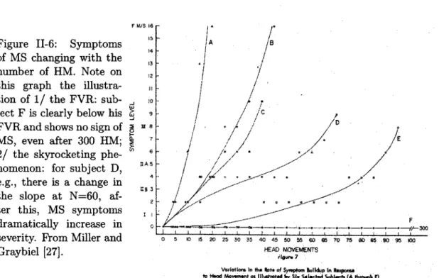
Miller and Graybiel [27] find that: MS symptoms appear to rise more steeply after a
8
Detailed discussion about this parameter is given in Appendix D.
34 CHAPTER I. BACKGROUND
certain number of HM, if the angular velocity of the chair is above the subject's functional vestibular reserve (FVR), as shown on figure 11-6. This phenomenon is captured in Oman's model described in the next section.
The mean value of the CSSI over all the subjects run is 15.3, which can be obtained by different combinations of E-factor and N. Some of them are shown in table 11.2. The text suggests that one HM is from one position to another (e.g. from front to upright), which is the same way as the AG counts the HMs. A CSSI of 15.3 corresponds to performing 42 HM at 23 rpm (as suggested in table 11.2). It is consistent with the number of HM that subjects have been able to perform in the AG experiments. Past AG-experiments were designed with generally more than 36 HM, leading to reasonable drop-out rates due to MS. A study (Brown, [5]) involved ad-lib yaw head-turns: most of the subjects were able to do between 40 and 100 such HM.
C. FROM STIMULUS TO RESPONSE: DESCRIPTION OF THE RESPONSE
Figure II-6: Symptoms of MS changing with the number of HM. Note on this graph the illustra-tion of 1/ the FVR: sub-ject F is clearly below his FVR and shows no sign of MS, even after 300 HM; 2/ the skyrocketing phe-nomenon: for subject D, e.g., there is a change in the slope at N=60, af-ter this, MS symptoms dramatically increase in severity. From Miller and Graybiel [27]. F INS 16 15 14 13 12 5-0 It t0 6 ISA 5 4 3 2 - --I -- -0 5 10 15 20 25 30 35 40 45 50 55 C-0 65 70 75 80 85 .90 95 100 HEAD MOVEMENTS gearw 7
Variatit in the Pbte of Syrepaom BkIuip in Respoos to Head Movement as fituwoted by Six Seiseted Subjects (A through F)
Centrifuge velocity (rpm) E N
2 0.00397 3854
10 0.078 196
23 0.367 42
30 0.60 26
Table II.2: Combination of E and 15.3.
N values which correspond to the mean value of CSSI: 35
![Figure 11-5: The CSSI test. From Miller and Graybiel [27].](https://thumb-eu.123doks.com/thumbv2/123doknet/14090553.464695/32.918.194.725.151.1010/figure-cssi-test-miller-graybiel.webp)

![Figure II-10: Nausea path symptom dynamics. From Oman [32].](https://thumb-eu.123doks.com/thumbv2/123doknet/14090553.464695/41.918.191.741.538.863/figure-ii-nausea-path-symptom-dynamics-from-oman.webp)