A Battery Powered Near Infrared (NIR) Camera for the MIT
HelioDome
by
Keith M. Molina
SUBMITTED TO THE DEPARTMENT OF MECHANICAL ENGINEERING IN PARTIAL FULFILLMENT OF THE REQUIREMENTS FOR THE DEGREE OF
BACHELOR OF SCIENCE IN MECHANICAL ENGINEERING AT THE
MASSACHUSETTS INSTITUTE OF TECHNOLOGY
JUNE 2008
02008 Keith M. Molina. All rights reserved.
The author hereby grants to MIT permission to reproduce and to distribute publicly paper and electronic copies of this thesis document in whole or in part
in any medium now known or hereafter created.
Signature of Author:
Depa Cment of Mechanical Engineering
May 9, 2008
Certified by:Dr. Warilyne Andersen Assistant Professor of Building Technology Thesis Supervisor Accepted by:
John H. Lienhard V roessor of Mechanical Engineering
MASSACHUS NOOS I E Chairman, Undergraduate Thesis Committee
OF TECHNOLOGy
AUG 1R
2008
ARCHAVE
A Battery Powered Near Infrared (NIR) Camera for the MIT
HelioDome
by
Keith M. Molina
Submitted to the Department of Mechanical Engineering On May 9, 2008 in Partial Fulfillment of the Requirements for the Degree of Bachelor of Science in
Mechanical Engineering
Abstract
Research in advanced fenestration systems has led to the development of the Heliodome project at the Massachusetts Institute of Technology Daylighting Laboratory. The MIT Heliodome project is dedicated to goniophotometry and the assessment of bidirectional photometric properties of light- (or heat-)redirecting facade systems by using digital cameras as multiple-points photosensors, that cover the visible and near infrared portions of the sunlight spectrum.
Two cameras are used in this device: a charge couple device (CCD) camera using silicon detectors and a near infrared (NIR) camera using InGaAs sensors. Both cameras are mounted to a table which has two degrees of rotational freedom, altitude and azimuth. Using the rotating table and cameras in combination with an ellipsoidal dome, which is
coated with a semi-transparent specula coating, allows a time-efficient and continuous measurement of bidirectional transmission (or reflection) density functions (BTDFs or BRDFs).
This thesis seeks to enhance current Heliodome operations by developing a portable power source for the NIR camera. A portable power system has been designed and constructed to operate the NIR camera during measurement sessions. The portable power system allows the rotating table to rotate completely free of constraints caused by weight, imbalance, power and light path obstruction issues. This contribution to the Heliodome project provides the user with more reliable data and relief from disorderly setup.
Acknowledgements
Special thanks to my thesis supervisor, Dr. Marilyne Andersen, for her support and guidance in the development of this thesis and prior research done in the undergraduate research opportunities program.
Many thanks to my colleagues in the bat cave, Javier Burgos, Danh Vo, Jason Ku and Samuel Kronick for their advice on various design problems in mechanical and electrical engineering methods.
A big thanks to Marc P. Hansen, applications engineer at Sensors Unlimited for his help with the NIR camera and acquisition of related circuit diagrams and spec sheets.
I would also like to thank my friends and family for their support in my endeavors and their patience with my dedication to work.
This work was jointly supported by the Massachusetts Institute of Technology and the National Science Foundation under Grant No. 0533269. Any opinions, findings and conclusions or recommendations expressed in this material are those of the author(s) and do not necessarily reflect the views of the National Science Foundation (NSF).
Table of Contents
1 Introduction 6
1.1 Natural Light and Us 6
1.2 Going Green 6
1.3 Advanced Fenestration Technology 7
2 The MIT HelioDome Project 7
2.1 Main Components 8
2.1.1 Table 8
2.1.2 Illumination System 9
2.1.3 Cameras 10
2.2 Equipment Concerns 11
2.2.1 Rotating Table Design 11
2.2.2 Weight and Balance 12
2.2.3 Camera Placement 12
2.2.4 Power Issues 12
3 Near Infrared (NIR) Camera: Issues and Constraints 13
3.1.1 Existing Equipment and Camera Setup 13
3.1.2 Power Supply Concerns 14
3.1.3 Possible Solutions to Power Concerns 15
4 Design and Development of Battery Powered NIR Camera System 16
4.1 Portable Operation 16
4.2 Circuit Design 16
4.2.1 Existing Power Supply Design 17
4.2.2 Switching from AC to DC 19
4.2.3 DC to DC Converter Design 20
4.2.4 Circuit Testing 21
4.2.5 Overall Circuit Architecture 22
4.2.6 Circuit Housing 23
4.3 Battery System 24
4.3.1 Battery System Testing 25
4.4 Table Incorporation 25
4.4.1 System Arrangement and Integration 25
5 System Operation 26
5.1 Operating Specifications 27
5.2 Original System to New System Comparison 27
6 Conclusion 27
6.1 Achievements 27
6.2 Further Investigation 28
6.3 Applications 28
7 Appendix 30
7.1.1 Filter Wheel System 30
7.1.2 Beam Shaper 33
7.1.3 Light Source Support 34
7.1.4 Illumination Positioning System 35
7.2 Front Panel 36
7.3 HTC-1500 37
7.4 Temperature Controller Interfacing 50
7.5 Linear Voltage Regulators 51
7.5.1 LM2937 51
7.5.2 LM2940 64
7.6 Switching Regulator 82
1 Introduction
Recently, in the field of architecture, an effort to redesign lighting systems and fenestration systems has become a main focus. New strategies to light entire buildings using mainly natural light are being developed as well as new materials that capture light energy to heat and cool structures. This will not only save energy otherwise consumed by fixtures and lamps, it also has major effects on humans psychologically and physiologically. This is why much effort is being put into the development of these systems and it is essential for architects and engineers to understand how light can be manipulated using different designs and materials.
1.1 Natural Light and Us
Numerous studies have been conducted to better understand the effects of natural light on humans. Evidence shows that light in general has vast psychological and physiological effects on humans. An experiment done with human subjects showed that people are drawn to areas that provide good lighting conditions such as daylight [Rea, 2000]. Serotonin, a neurotransmitter, has long been used to treat depression and aggressive behavior and has recently been discovered to have a direct correlation to luminosity of a given day [Bjorksten et al., 2005]. Insufficient exposure to natural light can also have adverse effects on the human body's ability to produce vitamin D which is essential to the uptake of calcium, a nutrient that helps to strengthen bones [Raymond and Adler,
2005].
1.2 Going Green
It has also become a necessity to design "green" structures that leave less of a footprint on our environment by reducing the amount of energy it uses to operate. Lighting and heating or cooling are the main sources of energy consumption in buildings and as structures get increasingly larger with new construction technology, so does the energy consumption. With current lighting systems and fenestration designs, the cost of lighting and heating using conventional fixtures and heating elements accounts for 30% to 40% of non-residential buildings' yearly energy costs [Scartezzini, 2003]. By studying the
abilities of different fenestration materials, efficient use of lighting can be achieved and used for the reduction of energy costs.
1.3 Advanced Fenestration Technology
With new technology in construction comes new design in fenestration. Over the past two decades more and more efforts are being spent in analyzing the ways in which fenestration can be manipulated for daylighting purposes. These smart fenestration systems are designed to redirect sunlight and daylight to the areas of rooms farthest away from the windows and control the amount of heat and light let in depending on changing sun angles and weather conditions over the year. Therefore, the combined angular and spectral control of solar energy and visible light becomes the main function of these advanced fenestration systems, aiming for maximal heat and light benefits in buildings that incorporate these smart systems [Gayeski, 2007].
2 The MIT HelioDome Project
The MIT HelioDome is a project dedicated to the study of materials and coatings used in such advanced fenestration technologies. It has two functions: the first is a video-based goniophotometer which measures the properties of various materials and coatings; and the second is a sun-course simulator which directs a beam of light to simulate the sun's course for any day and location. When a model-sized building is placed on the table it acts as a sun-course simulator by rotating or tilting the table to reproduce the effect of sunlight throughout a single day. The second function is designed to aid architectural students attending or visiting MIT to better understand the shading and lighting techniques they are incorporating into their building designs. When used as a goniophotometer, a mirror coated ellipsoidal dome is placed over two holes (the focal points of the ellipsoid) that bore through the rotating table. Light passes through the investigated material secured to one focal point while a camera collects data through the other focal point [Andersen et al, 2005].
Goniophotometry is the measurement of light intensity as a function of angle. The goal of the HelioDome is to measure Bi-directional Transmission (or Reflection) Distribution Functions, more conveniently called BTDFs (or BRDFs). These functions describe the
way light is distributed spatially after passing through the material under investigation. Establishing these functions for new materials will lead to further incorporation into building simulation programs and other computer aided design methods engineers and architects use in their design process.
As a sun-course simulator students can see how their materials actually work in its physical environment. The beam of light directed at the rotating table reflects and transmits through windows while taller structures block the light casting shadows over parts of the model. Here, the organization of the fenestration and its walls are critical and students can make better judgments on how to best orchestrate their designs. Glare is also a big factor when designing a building, especially when it is used for office space. This can be solved by good overall architectural design as well as through the use of special glare reducing materials.
2.1 Main Components
The Heliodome project at MIT has had much progress since its inception in 2004. A dark room located in one of MIT's basement labs harbors advanced optical equipment used in the Heliodome's program of study. Scheduled to be a useable workspace by the fall of 2008 the project has brought together students and faculty from many disciplines and backgrounds all in the pursuit of the Heliodome's success. Two major equipment groups of the project are a table which can rotate in both the azimuth and altitude axis and the optical sensors (or cameras). The cameras are the main measurement instruments in the project and the basis of this thesis project. Another equipment group is the filter wheel, beam shaper and Hydrargyrum medium-arc iodide (HMI) lamp which is organized on a wheeled carriage called the illumination system.
2.1.1 Table
The table built specifically for the MIT Heliodome project was designed and constructed by Dean M. Ljubicic as a senior thesis project [Ljubicic, 2005]. The main features of his design are aluminum framing and an aluminum honeycomb table. The table is driven by two motors and rotates on a system of ball bearings for smooth movement between
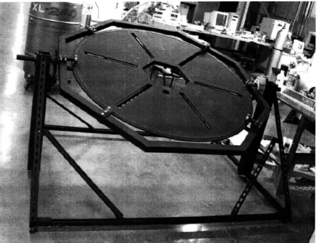
positions. The main octagonal-shaped hole in the center of the table incorporates several plates that allow clamping of the materials being investigated. When not in use, a flat plate is placed over the hole so that models can be clamped to the center of the table. The smaller, circular, hole near the edge of the center hole is where the cameras are placed to take data when the table is used as a goniophotometer. All of these attributes can be seen in figure 1.
Figure 1. The MIT HelioDome table with two degrees of freedom, azimuth and altitude.
It uses two motors to rotate and the main circular section is constructed of honeycomb aluminum for its low mass and high strength. The framing and supports are made of aluminum box extrusions. (Photo courtesy of Prof. Marilyne Andersen)
2.1.2 Illumination System
The light source is an HMI lamp which mimics light produced by the sun [Browne, 2006]. A series of optical filters are housed in a filter wheel system that rotates in front of
the HMI lamp [Koch, 2007]. As part of the illumination system a beam shaper, whose role is to block unwanted light from the HMI lamp caused by the rotation of the table in the altitude direction is placed in front of the filter wheel system and HMI lamp [Browne, 2006]. These three components are housed in a custom-designed positioning system that was designed and constructed by the author. A detailed description of the positioning system and the filter wheel to whose construction the author was also involved is provided in the Appendix in section 7.1.
2.1.3 Cameras
The MIT Heliodome project uses two cameras. The first is a charge coupled device (CCD) camera covering the visible range and the beginning of the near infrared. The second camera is an Indium Gallium Arsenide (InGaAs) camera covering a range of 900 to 1700 nm in the near infrared and for the purposes of this paper will now be called the NIR camera. This is only used in goniophotometer mode and can typically be used to estimate the amount of solar heat gains in winter months versus summer months. The CCD and NIR cameras were selected to span the wavelengths over which the spectral power distribution of solar radiation is most significant. Both the visible and near infrared spectrums are spanned using these cameras and information gathered from the
cameras can be used to design a smart fenestration system.
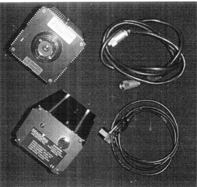
Figure 3. The Near Infrared (NIR) camera with universal power supply, plug and power
cable.
The main focus of this thesis is to improve the NIR camera's effectiveness in the Heliodome project.
2.2
Equipment Concerns
For seamless operation the table and cameras must observe specific guidelines which were worked into the table design. In this section an overview of the guidelines dictating the table operations and camera placements are given.
2.2.1 Rotating Table Design
The existing table has the following functional requirements which must not be compromised [Ljubicic, 2005]. First, the table must rotate 3600 in the horizontal rotation axis in relation to the ground (altitude); Second, the vertical rotation axis must rotate 3600 in relation to a vertical axis normal to the ground (azimuth); Third, the maximal load must not exceed 400 Newtons; Fourth, no hardware can hinder the incoming light in BT(R)DF mode from the top or bottom of the sample and; Fifth, the device should require minimal maintenance and setting up. These parameters must be kept and will be
referred back to in later sections to make sure there are no obstructions to the table function.
2.2.2 Weight and Balance
As a standalone unit the rotating table works seamlessly and when something is placed on the table for both the video-goni0photometer function and the sun-course simulator, the movements of the table must also be seamless. Some concerns that have risen since the use of the table with actual ellipsoids and large scale models are imbalance due to weight distribution. Though the table's motors are strong enough to hold a position even though a large mass is on the table it is important that an object attached to the table has its center of mass near the center of the table. If this is not possible then a counterweight must be attached to the table, not exceeding the table load limits. This is essential to the smooth movements of the table to its various positions.
2.2.3 Camera Placement
The cameras are secured to the table so that the lens fits through a small circular hole as mentioned in a previous section. This small circular hole is the focal point of the ellipsoid dome placed on the table when used as a goniophotometer. When light is shown through the focal point at the center of the table all the light distributed in the dome is reflected to the camera's lens which is strategically placed at the other focal point. By covering the center hole with a material specimen and shining a light through, the camera detects the amount of visible (using the CCD camera) or near infrared (using the NIR camera) light transmitted and a BT(R)DF is generated by computer software. Only one camera can be placed on the table at a time and is secured using an "L-shaped" metal brace and machine screws [Ljubicic, 2005]. The camera is oriented so that the lens is parallel to the table therefore situating it's length perpendicular to the table. The NIR camera is 15.8cm in length and protrudes 13.3cm out of the plane of the table and supporting struts.
2.2.4 Power Issues
The CCD camera can be powered by either an AC adapter that can be plugged into a wall outlet or by a universal serial bus (USB) connection on a personal computer. The NIR
camera, on the other hand, is electrified by a power supply which must be plugged into an AC outlet supplying 120V. When the NIR camera is used for goniophotometry, the wiring for the camera and power supply obstructs both axis of the table's rotation. Also, the power supply that must supply the power to the camera is very large and must be suspended on the under the table during operation. This often leads to cumbersome set up and obstruction of the light's path to the focal point located at the center of the table. Problems concerning the table's rotation as well as managing the bulky power supply were the main motivations for the formulation of this thesis and for designing a portable power solution for the NIR camera.
3 Near Infrared (NIR) Camera: Issues and Constraints
The NIR camera is designed by Sensors Unlimited, Inc. and its full name is SU320-1.7RT Indium Gallium Arsenide Near Infrared Camera. It is a compact versatile imaging tool designed for laboratory and field use and has an optical sensitivity range of 1.Ojpm to 1.7pm. It has dimensions 15.8 x 10.2 EXT
O
TRIGGER IN
TIME
±
SENSORS
UNLIMITED, INC.
I
D
N
G
E
I R
T F
A
A
L C
EiE
O
x 10.2 cm not including the lens whose length and diameter varies with the type of lens used. Figure 4 shows a diagram of the camera's connection terminals located on a panel opposite the lens.
Figure 4. SU320-1.2RT back panel.
For this project, only the POWER/TEC port is affected which is the camera's connection to the main power suptlv.
3.1.1 Existing Equipment and Camera Setup
The SU320-1.7RT NIR camera comes complete with a universal power supply and power cable. Power is provided via a 12-pin Hirose connector on the back panel. This supplies power both for the camera functions and for the thermoelectric cooler in the
I
focal plane array. The power supply must be plugged into a 95-220V AC outlet and it's dimensions are 16.5 x 11.4 x 8.9cm.
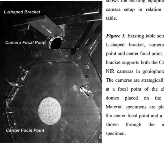
The NIR camera is attached to the table via L-shaped bracket as mentioned in a previous section. The power supply must be suspended from the table to allow for maximum table rotation without crossing the power cable and plug. This is achieved by securing the power supply in a nylon pouch and tying the pouch to the table using straps. Figure 5 snows the existing equipment and camera setup in relation to the table.
Figure 5. Existing table setup with
L-shaped bracket, camera focal point and center focal point. The L bracket supports both the CCD and NIR cameras in goniophotometry. The cameras are strategically place at a focal point of the ellipsoid
domes placed on the table.
Material specimens are placed at the center focal point and a light is
shown through the material
specimen.
3.1.2 Power Supply Concerns
From the existing NIR camera setup it is not possible to rotate the full 3600 because the power supply plug must be secured to a wall outlet which is not in the reference frame of the rotating portion of the table. Therefore, full rotation would tangle cords and potentially disrupt table operation. The current maximum table rotation in the altitude direction allowed when using the NIR camera is 1800 from the initial vertical position.
The maximum table rotation in the azimuth direction allowed when using the NIR camera is 3300 respective to its starting position. This is in direct contradiction with the first and second functional requirements of the table design which is to have 3600 of table rotation on both axis. Another concern is the obstruction of the light's path to the center of the table (a focal point of the ellipsoid). During table rotation, the current setup tends to cross the path of the light. Extra care must be taken to make sure that the pouch, straps, or cables do not cross the path of light often making it difficult to operate the camera and table simultaneously.
3.1.3 Possible Solutions to Power Concerns
Issues concerning the electrification of the NIR camera are the main driving force for this project. After brainstorming several options for a portable power solution to the NIR camera the idea for a battery-powered NIR camera was decided upon.
Another option that was explored was to place an AC outlet within the frame of reference of the camera and power supply so that free rotation could be achieved. Although the idea of an AC outlet on the table had potential, safety concerns came into play because the only way power could be placed on the rotating table would be via slip disks which are bare copper disks spanning the circumference of the table. These bare copper disks would be electrified with 120V of AC power, a potential risk to those operating the table and camera.
The idea for a battery-powered NIR camera came from Professor Marilyne Andersen, who thought it would be easier to achieve within the time frame allotted for this project. After delving deeper into the capacity for powering an NIR camera with batteries alone it was thought a good fit for the Heliodome project.
4 Design and Development of Battery Powered NIR Camera
System
The design and development of the battery powered NIR camera system incorporates three main phases: building the circuit, choosing a battery system and attaching the entire
system to the rotating table.
4.1 Portable Operation
The idea of a battery powered NIR camera system involves removing the universal power supply and power cable and replacing it with a battery system. This is not as easy as it sounds because as mentioned above the power cable supplies not only power but also regulates the temperature of the focal plane array located inside the NIR camera. This means that the camera's focal plane array has a connection to the power supply via the 12-pin Hirose connection cable. Therefore two items are controlled by the power supply: electrifying the camera and regulating the focal plane array temperature. A circuit must be designed to not only supply the needed voltages to electrify the camera, but also communicate with the focal plane array within the camera.
4.2 Circuit Design
The first phase of designing the battery powered NIR camera system is the circuit design. The NIR camera connects to the power supply via a 12-pin Hirose connection cable. Figure 6 shows a diagram of the 12-pin Hirose connector and its corresponding pin numbers.
Figure 6. (a) Diagram of 12-pin Hirose connector which supplies the power to the
camera and controls the focal plane array. (b) Photo of 12-pin female Hirose connector used in final circuit design.
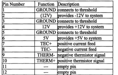
Each pin corresponds to either a voltage (for electrifying the NIR camera) or a signal (for controlling the focal plane array). The following table lists the pin and corresponding functions.
Pin Number Function Description
1 GROUND connects to threshold
2 (12V) provides -12V to system
3 GROUND connects to threshold
4 12V provides +12V to system
5 GROUND connects to threshold
6 5V provides +5V to system
7 TEC+ positive current feed
8 TEC- negative current feed
9 THERM- negative thermistor signal
10 THERM+ positive thermistor signal
11 --- empty pin
12 --- empty pin
Table 1. Pin numbers and corresponding functions. This information was taken from the
front panel assembly specification sheet '4120-0028 PSA front panel' shown in the appendix under Front Panel.
All voltages listed in table 1 should be held constant for the camera to operate normally. The focal plane array temperature is monitored by a thermistor located inside the camera and is controlled by a temperature controller located inside the power supply. The pins that control the focal plane array are pins 7 thru 10. These pins are connected to a temperature controller which is in turn powered by its own +8V voltage, another voltage to consider when designing and electrifying the circuit itself.
4.2.1 Existing Power Supply Design
The existing power supply is very large due to the massive amounts of converting that the device must do. The power supply takes one AC voltage signal, converts it to a DC voltage and then divides it among the pins that need a constant voltage and also a +8V
needed to electrify the temperature controller. The temperature controller used in the power supply design is an HTC Series - Hybrid Temperature Controller designed and manufactured by Wavelength Electronics. The HTC-1500 (see HTC-1500 in appendix for specifications) achieves 0.001"C temperature stability and comes in a low profile package with a 20-pin DIP connection. Figure 7 below shows a picture of the
HTC-1500.
Figure 7. Photo of HTC-1500
temperature controller designed and manufactured by Wavelength
Electronics. The specification sheets for this temperature controller are in the Appendix (section 7.4).
A separate circuit is needed to operate +1h
t
e IT
UH'•T-
1- 1"500V
coretly.
Forv
the
purposes of research, the needed circuit diagram was acquired from Sensors Unlimited. This circuit diagram is detailed in the appendix under Temperature Controller Interfacing. Table 2 shows the pin numbers and corresponding names and descriptions for theHTC-1500.
PIN NAME DESCRIPTION
1 LIMIT - Resistor value of 0 Q to 1 M9 between pins 1 & 2 limits maximum output current.
2 LIMIT + No resistor is necessary when operating at maximum HTC current
specification.
3 PID OUT Short pins 2 & 3 for bipolar operation.
Install diode for unipolar operation (see page 6, step 1 for polarity) 4 V REF OUT 3.675 Volt Reference < 50 ppm stability (15 ppm typical)
5 COMMON Measurement ground. Low current return used only with pins 6, 7 & 8. Internally shorted to pin 10.
Temperature monitor. Buffered measurement of voltage across Sensor+ 6 ACT T MONITOR&
Sensor -.
7 SET T MONITOR Setpoint monitor. Buffered measurement of the setpoint input (pin 8). SETPOINT
INPUT Remote setpoint voltage input. Input impedance = 1 MK2
Contact Factory for higher voltage operation. 10 11 12 13 14 15 16 17 18 19 20
Table 2. Pin descriptions for the hybrid temperature controller HTC-1500. This table
was taken directly from the HTC-1500 specifications sheet located in the appendix.
Also included in the power supply design is a red light emitting diode (LED) which illuminates when power is supplied to the NIR camera. An on/off switch is also included to control the input of power from the AC outlet. All of these power supply design features were incorporated into the circuit although somewhat modified for the adaptation of a battery system which supplies a DC voltage.
4.2.2 Switching from AC to DC
The existing power supply converts an AC voltage to a DC voltage and then distributes the voltages where needed. It is simply an AC to DC converter and what this project is trying to do is replace the power supply with a battery system which supplies a DC voltage. Theoretically, this process involves taking the front end of the current power supply design which is made up of transformers, removing them and then creating a direct connection from the battery system to the various voltage pins. Once the conversion is made the circuit is called a DC to DC converter.
GND TEC + TEC -SENSOR + SENSOR -RBIAS + RBIAS -RPROP + RPROP -C INT + C INT
-Power Supply Ground. Used with pin 9 for high current return. TEC+ & TEC- supply current to the TE module. With NTC sensor, connect TEC+ to
positive lead of TE module. With PTC sensors, connect TEC- to positive lead of
TE module.
A sensor bias current will source from Sensor+ to Sensor- if a resistor is tied
across RBIAS+ and RBIAS-. Connect a 10 kM resistor across Sensor+ & Sensorwhen
using an AD590 temperature sensor. See page 6, step 4.
esistance between pins 15 & 16 selects sensor current from 1 pA to 10 Range is 0 11 to 1 MQ.
Resistance between pins 17 & 18 selects Proportional Gain between 1 & 100.
Range is 0 Q to 495 kM.
Capacitance between pins 19 & 20 sets the Integral Time Constant between
0 and 10 seconds. 0 seconds (OFF) = 1 MCI resistor 0.1 to 10 seconds = 0.1 gF to 10 gF.
4.2.3 DC to DC Converter Design
The DC to DC converter portion of the circuit takes one DC voltage signal from a battery and converts it to several different voltages necessary to electrify the NIR camera. Table 1 shows that pins 2, 4 and 6 needs voltages of -12V, +12V and +5V respectively. In addition to the three voltages mentioned a voltage of +8V is needed to electrify the temperature controller, pin 9 from Table 2. The DC to DC converter must supply four different voltages to operate the camera successfully. This task is easy for the positive voltages because the battery supplies one positive voltage which can then be converted to other positive voltages via linear voltage regulators. It would be trivial to get -12V from a battery if only negative voltages were required, but since the DC to DC converter must supply both positive and negative voltages a different type of voltage regulator is needed. The final DC to DC converter design incorporates three linear voltage regulators to supply the positive voltages and one switching regulator to supply the negative voltage.
The linear voltage regulators selected for the +5V, +8V, and +12V are the LM2937ET, LM2940T and LM2940CT linear voltage regulators from National Semiconductor (specification sheets for the LM2937ET, LM2940T and LM2940CT are located in the appendix under Linear Voltage Regulators). They each have three prongs and require two capacitors each to operate. The +5V linear regulator requires an .1 microfarad capacitor between its input terminal and ground while a 10 microfarad capacitor is required between its output terminal and ground. Similarly both the +8V and +12V linear regulators require a .47 microfarad capacitor and a 22 microfarad capacitor in the same orientation. These linear regulators are of the same type used in the existing power
supply and are displayed in Figure 8.
Figure 8. Photo of linear regulators. From
left to right: +5V LM2937ET, +8V
LM2940T, +12V LM2940CT. Specification sheets for these regulators can be found in the appendix under Linear Voltage Regulators.
The switching regulator selected for the -12V is the PTN78000A from Texas Instruments. This regulator has five pins and is adjustable. Table 3 shows the pin numbers and its corresponding functions.
Pin Function Description
1 V OUT The negative output voltage power node with respect to the GND node.
- It is also the reference for the V OUT adjust control inputs.
2 V IN The positive input voltage power node to the module, which is
- referenced to common GND.
3 N/C This pin is active and must be isolated from any electrical connection.
A 1% resistor must be placed between pin 1 and pin 4 to set the output voltage of the module lower than -3V. If left open-circuit the output 4 V OUT ADJUST voltage defaults to -3V. The temperature stability of the resistor should
-be 100ppm/0
C (or better). The set point range is -15V to -3V. The standard resistor value for a number of common output voltages is
rovided in the application information.
5 GROUND The common ground connection for the VI and VO power connections.
Table 3. Pin numbers and its corresponding functions for PTN78000A from Texas
Instruments. This data is taken from the PTN78000A specification sheets located in the appendix under switching regulator.
Figure 9. Photo of
PTN78000A, a switching regulator used to generate a
-12V for the DC to DC portion of the circuit design. The specification sheets for the PTN78000A can be found in the appendix under switching regulator.
4.2.4 Circuit Testing
The completed circuit was tested using a lab power supply first using +15V and then +20V. It was found that with + 15V the DC to DC converter portion of the circuit would
supply erratic voltages instead of constant voltages which the NIR camera needs. With +20V supplied from the power supply stable voltages were met and thus a +20V requirement was set for the battery system explained in a later section. Table 4 shows the voltages produced by the DC to DC converter.
Pin Pin Reference Voltage Required (V) Measured Voltage (20V)
2 Hirose connection -12.0 -11.8
4 Hirose connection 12.0 12.1
6 Hirose connection 5.0 5.0
9 HTC-1500 8.0 8.0
Table 4. DC to DC converter voltages produced using +20V from power supply.
4.2.5 Overall Circuit Architecture
The circuit has two parts: the temperature controller portion for the HTC-1500 and the DC to DC converter portion. The circuit fits on one bread board which is 16.5cm by 5.7cm and its height is 5.7cm due to the orientation of the HTC-1500. The two parts of the circuit splits the bread board in half and the entire board is used allowing for maximum flow of heat away from the HTC-1500 and the voltage regulators. This circuit orientation is especially useful to the entry of the battery connection and the exit of the power cable to the camera. The entire circuit is displayed in figure 10 below and is the
Figure 10. Photo of circuit in plastic housing. The left half of the circuit contains all the
circuitry necessary to run the temperature controller. The right half of the circuit contains the DC to DC converter which supplies the power necessary to run the camera and to power the temperature controller.
4.2.6 Circuit Housing
To protect the circuit from its environment a plastic housing was built. The plastic housing is a rectangular box with dimensions 19.1 x 8.3 x 7.0 cm. The housing includes an on/off switch and a red LED for user convenience and has a female 12-pin Hirose connector on one end for connection to the camera. On the end opposite the Hirose connector there is a protective bushing for the battery cable. The circuit and housing package weighs one kilogram.
(a)
(b)
Figure 11. (a) Photo of entire housing and circuitry from the 12-pin Hirose connection
end. (b) Photo of entire housing and circuitry from the battery wire bushing and LED end.
4.3 Battery System
The battery system consists of a battery which supplies one voltage signal and its charger. Some requirements for the battery are that it has a high energy density and can supply a positive twenty volts of DC power and one amp of current for four hours. The one amp of current was determined by the NIR camera specifications which require one amp to operate.
A battery with very high energy density helps to keep the mass of the battery system at a minimum. Although lithium ion batteries have the highest rating for energy density it is very costly and runs a high risk of spontaneous combustion. Lithium ion batteries also require onboard monitors to keep from over-charging often leading to its high price. A nickel metal hydride (NiMH) battery was chosen in the end for its manageable cost, easy setup and smart charging. See figure 12 below for a photo of the battery chosen for the
system.
The NiMH battery is rated for 20V and 4200mAh. When discharging at a rate of 1A per hour at 20V the NiMH battery lasts up to four hours meeting the requirements set for the battery system. The battery has dimensions 18.4 x 8.9 x 2 cm and weighs 1.4 kg.
4.3.1 Battery System Testing
Initial testing of the entire circuit and battery system provides similar voltages and data as taken when testing the circuit with a lab power supply. The following table displays the voltages measured with the battery system in place of the lab power supply.
Pin Pin Reference Voltage Required (V) Measured Voltage (20V)
2 Hirose connection -12.0 -11.8
4 Hirose connection 12.0 12.1
6 Hirose connection 5.0 5.0
9 HTC-1500 8.0 8.0
Table 5. DC to DC converter voltages produced using +20V from battery system.
4.4 Table Incorporation
The third task of this project was to attach the entire circuit and battery system to the table without affecting the functional requirements of the table and then integrate it with the NIR camera.
4.4.1 System Arrangement and Integration
The battery and circuit system weighs a total of 2.4kg. To keep the table in a balanced state the decision was made to attach the battery and circuit system opposite the NIR camera and corresponding mounting bracket. Since each component weighs about the same they counter each others weight allowing the table to stay in balance when in operation. The cable connecting the battery to the circuit is secured to the circuit box via a Velcro strap. The cable connecting the circuit to the NIR camera is run along the main struts of the table also using Velcro straps that are attached to the table permanently. The battery and circuit system attaches to the table via glued on Velcro straps that loop around the circuit and battery tightly. The Velcro straps allow the battery and circuit system to virtually be in the plane of the table and out of the way of the light path to the
center of the table. The secure straps also keep the battery and circuit system snug against the table so that it does not swing hindering the movements of the table. When fully attached the battery and circuit system and included cables do not obstruct the light path to the center of the table and also allows the table to rotate in both the altitude and azimuth directions at its full potential (3600). The weight of the battery and circuit system also meets the table requirements as it is about the same weight as the power supply used in the original setup.
Figure 13. Photo of battery and circuit system setup.
The next steps to this project are to connect the NIR camera output cable to the table's onboard laptop and test the system altogether.
5
System Operation
After arranging the battery and circuit system on the table and attaching it to the table it was time to test the system. The NIR camera worked seamlessly with the new circuit just as before and the table requirements were not obstructed.
5.1 Operating Specifications
The battery powered NIR camera operates for up to four hours on a fully charged battery. This allows for the full use of the system for an entire session. The system can either be removed from the table for charge as a whole or just the battery can be removed and charged. With an extension cord, the battery can be charged while attached to the table. Total charge time for a fully charged battery is about two hours and is charged via a smart charger so that the cells can never be overcharged. System setup takes less than three minutes not counting the time it takes to secure the NIR camera to the mounting bracket.
5.2 Original System to New System Comparison
The new battery powered system works just as well as the original system which used the AC powered power supply in terms of NIR camera operation. The new system is better because it is now a portable device which allows the table to rotate freely in all directions without hindrance from cables. Another feature that the new system has over the original is the compact size of the battery and circuit system which snugly fits in the plane of the table. Cables are also secured to the table so that they do not obstruct the light path to the center of the table.
6 Conclusion
6.1 Achievements
This project attempted to develop a battery powered near infrared camera and was successful in doing so. Development involved the design of a circuit, battery system and incorporation into the existing architecture of a rotating table with two degrees of freedom.
One limitation caused by the project is a time limit on the use of the NIR camera when used portably, which is a function of the battery life. This limitation is acceptable because the previous setup inhibited the table from rotating freely, a functional requirement of the table design. The battery pack can be charged in two hours and lasts
up to four hours during full operation. This gives an average of one and a half sessions using the camera per day.
Overall the project invoked many learning opportunities in circuit building and testing as well as battery system selection. About 40% of the project involved research in electrical engineering methods and testing; 40% incorporated mechanical engineering methods and reasoning and; 20% involved manufacturing in hands on shop work.
6.2 Further Investigation
Optimization would be most urgent to complete in any further investigation of this project. Possible benefits of optimization are a longer lasting battery system and a lighter system if further battery research is completed.
For optimization of the DC to DC converter it is suggested that switching regulators replace the existing linear voltage regulators because they are more efficient at converting a large DC signal to a smaller DC signal, they give off less heat and are able to keep a constant voltage with small variations compared to the linear type regulators. Although switching regulators cost more upfront, big gains are made in efficiency allowing for a longer battery life and a longer NIR camera session.
6.3 Applications
The battery powered NIR camera is a useful tool in that it allows the full rotation of the rotating table in both the azimuth and altitude directions. To make the NIR camera portable a circuit was designed to emulate the existing power supply and a battery system replaced the power from the wall outlet. After doing all of this the NIR camera powered up and was able to take pictures and capture video in the same manner as it originally had. Therefore this project added value to the NIR camera system.
In the context of architectural advancement this paper has done little in that respect, but in the context of the MIT HelioDome project this paper has created a new device furthering the effectiveness of the project as a whole. With free rotation in the table as
opposed to the restricted rotation of the past, more angles can be explored in goniophotometry allowing for more data acquisition. This information is then analyzed and turned into BT(R)DF's which are useful to furthering advanced fenestration systems.
This portable technology has use in other fields not related to architecture. For instance, an NIR camera with portable capabilities can be used in unmanned vehicles used by rescue crews to take photos and capture video of hard to reach areas. Any type of portable surveillance is possible using this technology. As with the Heliodome project, portable technology like this can lead to more value-added projects in the future.
7 Appendix
7.1 HelioDome Illumination System
The author of this thesis entered the Heliodome project May 2007 as a participant in the Undergraduate Research Opportunities Program. The author's specific tasks were to calibrate the HelioDome illumination system by properly aligning a series of components between the light source and the rotating table thanks to a positioning system that was designed and constructed over the summer and fall sessions. An additional task included building a filter wheel system designed by a previous student in the Heliodome project.
The Heliodome illumination system had provided experience in many aspects of mechanical engineering. From drawing board to manufacture all mechanical engineering methods were applied including engineering calculations, material choice and CAD integration.
7.1.1 Filter Wheel System
A filtration device for selecting specific visible and NIR light wavelengths related to the red, green, and blue sensitivity peaks of a CCD camera and the pixel response for a NIR camera. This device functions with the Department of Architecture Daylighting Lab goniophotometer to profile the complete reflection and transmission properties for sample building materials (Koch 2007). This device was designed by Timothy Koch for his thesis in the spring of 2007 and constructed by the author of this thesis in the summer of
2007. The following sections explain what
The parts of the filter wheel system include the filter wheel, filter holders, Geneva drive and supporting frame:
Filter Wheel
The filter wheel, was designed to have 10 apertures for a total of 9 filters and one empty aperture to act as a void. The material choice suggested was a lightweight plastic for mass reduction and polyurethane was finally settled upon for its compressibility and ease
of machining. The size of the filter wheel was too large to machine in MIT's machine shop facilities so a redesign of the filter wheel assembly was done. The filter wheel was broken up in to smaller pieces with a special joining design called dovetails so that they could be fit together like a puzzle and glued into its final form.
Figurel4. Photo of final filter wheel
design sectioned and glued together. The dovetail design on the edges of the filter wheel individual pieces fit mated with the edges of other pieces completing a circular
filter wheel aPnemhlv
Filter Holders
The filter holders were circular rings of used to brace the different glass filters up against the apertures of the filter wheel. Rubber bushings squeezed against the filters holding them in place and protecting the filter from abrasive metals or plastic in the assembly. The materials selected for the filter
holders were polyurethane for the rings and neoprene for the rubber bushings. Unlike the filter wheel, the filter holders were small enough to be machined using MIT facilities without a redesign.
Figure 15. Photo of filter holders and
filter wheel. The filter holders brace the glass filters (not shown) against the apertures of the filter wheel using machine screws and neoprene bushings.
Geneva Drive
The function of the Geneva drive portion of the filter wheel system was to provide a reliable mechanism to apply a delay while advancing between filter aperture while rotating the filter wheel. There are two parts to the Geneva drive: the output wheel and the drive wheel. Polyethylene plastic was selected for the material used in both the output and drive wheels. While making manufacturing considerations, the same issues arose with the output wheel as with the filter wheel. A redesign was made and again, dovetails were used to create the puzzle effect and the output wheel was glued into its final form. The drive wheel, on the other hand, did not require a redesign.
Figure 16. Photo of Geneva drive. The
upper portion is the output wheel and the lower portion displays the drive wheel.
Supporting Frame
To hold the filter wheel system altogether a supporting frame was designed and
construction. Considerable redesign was made to the supporting frame due to
manufacturing issues and integration into a larger calibration system which was designed simultaneously with the filter wheel system and discussed in Appendix section 7.1.4. The material selected for the supporting frame was stainless steel due to its strength and rigidity. To add to the rigidity of the frame, L-shaped extrusions were selected and screwed together using stainless steel machine nuts and bolts. An A-frame style design was used to support a stainless steel rod which in turn supported the rotating filter wheel and Geneva drive. Motors were mounted on the frame and connected to the Geneva drive.
Figure 17. Filter wheel system including filter wheel, Geneva drive and supporting
frame. The supporting frame was made of stainless steel L extrusion and bolted together using stainless steel nuts and bolts.
7.1.2 Beam Shaper
For the goniophotometer application, it is important that the apparent beam on the material being characterized is the correct size. When the goniophotometer rotates on its altitude axis, the apparent beam will expand, becoming ellipsoidal. Without intervention, the apparent beam will °ood the surface of the goniophotometer when it is rotated to an extreme angle (nearly parallel to the ground). The apparent beam will be the wrong size unless something is put in its path to stop this excess light from reaching the table (Browne 2006). A "beam shaper" was developed which stops this occurrence and the author of this thesis construction a new supporting frame for it which was integrated in a larger calibration system.
The beam shaper supporting frame was designed in much the same way as the supporting frame for the filter wheel system. Stainless steel L extrusion and nuts and bolts were
used to create an A-frame which supported a platform housing the base of the beam shaper.
(a
Figure 18. (a) Beam shaper on previous frame made of partical board. (b) Redesigned
frame using stainless steel L extrusion.
7.1.3 Light Source Support
The light source for the goniophotometer must mimic sunlight as closely as possible. It must be collimated (up to 5± of spread- justification for this value is discussed later in this section), have a color temperature similar to the sun (approximately 6,000 Kelvin), have a spectral output similar to the sun, and be uniform in its emission such that all areas are illuminated equally. An Hydragyrum medium-arc iodide (HMI) lamp was selected as a light source for the goniophotometer (Browne 2006). To incorporate the HMI lamp into the larger calibration system a light source support was constructed using stainless steel L extrusion and stainless steel nuts and bolts.
Figure 19. Light source support made of stainless
steel L extrusion. The three comers of the triangular shape support the three legs of the HIM lamp tripod.
7.1.4 Illumination Positioning System
The purpose of the illumination position system was to develop a mechanism which allows the easy replacement of the filter wheel system, beam shaper and light source into the correct position for the goniophotometer setup.
The design of the positioning system includes a main rectangular frame made of stainless steel L extrusion for its strength and rigidity. It is a large structure, but very low to the ground because the filter wheel is very tall and must light up with the center of the table about three feet off the ground. Caster wheels are included in the design to make the rectangular frame mobile and easily removable from the rotating table. The mobile positioning system attaches to the rotating table using C-clamps and the illumination components are dropped into the rectangular frame from above.
Figure 20. Illumination
Positioning System for MIT HelioDome Project. The device allows easy setup of illumination system
NOTES,
L ASSERBLY tI ACCMD-AICE WITH [PCM-A-6t AND SUI 440-0045
LED-LED+ Jrn-JH-& FR ..13-6 J5-2 J3-5 J3-3, JU-2 J4-1 J2-1 I .@s-= ap 4 I
de-4
#pa BLK Is L1 #22 VHT 5 LG #Ep GRY 5 La #k2 RED 6 LF #2?V LK 10 Li-#22 yHT 5 LU #E WHK 6 LG 0R L 5 14] # TL 6 LG -OUE TEL 6 L UIN LG +12V THERl~S IL-TL+ +xv +1V WI~k •UFWIP-r LLILLM• LLhd SENSORS UNLIMITED I ,; PRDPRIETARY INFORMATION 8000-0025 8000 -O024 NHA 7000-1014 * ~ 1no tr hn F :rarU~0En. :*%IL %mORS l DEC w$ ME,±1/A ELxxx t.%K t/
xx ±aOS 4ATERMALf
FINISH,
APPI WAEIF
IA-DATE PAWiWi STARTED
pVALS DATE
rltP 4B/ 21 5a,0
CHECKED tYI
ENTR GEPT.
SENSORS UNLIMITED INC.
E CA CCDE E DRAwtC I
GALE! I 0I0OT S fL IHEET OF 1
...
..
GRY 5. GAT 5* BLk isl*"TI~C~-7RD ~~ ORN 5*L1 YEL 6• - -LU 5* BLK(2) * RED 6* ETIL BLKto-VHT(e) 6*DETAIL 'A'
• W ¸ [ ~ .. I II .. -1 ~ 1 I -~ I-- IV~... --- ~ ·-- ··---plaE ggkp(ECTE T --- ---c --- r~-- --- --- ---~I ---~ .---- ~I APPLICATION WOWnes ~1~111~- -~-·1~1 ---- APPLIATIOa---7.3 HTC-1500
HTC Series
-
Hybrid
Temperature Controllers
GeemrDescrfp1on
The advanced and rellatbWeroy of .He TC
series eusily achieves O.OOI*CIqrnpratuestataty. fIs smat. low profile page is deordesignslthspce
canslrain&s Thmelnearc Plannwralbopand tuipolalrrfaet
sourE a anuwtuw n alhaidd strat mm b teie
The H temperantre conrollers are easy
arnn edtranydesigpt Vtualyanytypeafbqmprale snsmorcete usedwili•he TCmatbils•te as
curmet smumr simplAes use •t reisin teumperatt•e
SOMA .1,•...
(P) and hitegrator Tim Consant (t) can be mailied to
capln pnatueavershon andstablt
Other feshms aaded n exuaby A single
resitor sets he maximm oulp curtrnt to your lod. Add s •auntsian iadle at peraaesisvhelmatws
with a u•ipol• uput current An anb•a referenmce
vttagdsimnyfespaolemetsrcmlrtdafitiaterperdaue selpoit Yuasouetapertereumohlywithan.
eXt ids*p*tvowIge Twomnitarpsgproaeaccese
totatemperab e Aase#Pnvclgeandrtheactualsensmr
_________ Featusres Sx
* CampuatSiza-15andS.OAmpoIadesS
* I Wntwbcsith Themislr. IC Senas. & IRTDs
* Sngle supcperaly an *5 V ta +42VDC
.Greutnhn +8 Vcasplancewwh +12V iput
* S ltbiltcOD O 0IOC -even aatint
* Tmarowra etairt Oupu Cuamt Lwit
SSer s.Prlmdonahl Gain, and 9elr -A Tmeca•nsartUswA•ustable
" MoniroutpulsforTempratmSelpaintand
AdualTwvperatur
" ur neerBipolrar Urnpdwer Qlpu-aperafts
thOwmoeleWics arresislkve heaters
Ordering Information
870.450 1.S A Temperase Cuntrolter HTC-3008 S0 Any Tenpersadhe CoGtoller
gPWRPAK43V +.5 *A PaOn Sgply
Functional Diagram
oncr
rar
Su".
Rum
-CaR~~~~~~~~ -to.1416frtcnca ~~~ w wtawvleghctupr
V'I
Pin Descriptions
PIN IMME DESCRIPTION
1 LIMIT - Resistor value of 0 0 to 1 MD between pins 1 & 2 limits meanum output current 2 LIMIT + N i t r i h e ti t ma i HTC t ifi ti
3 PI OUT Short pins 2 & 3 for bipor opemation.
Install diode for unipolur operetion (see page 6, step 1 for polarity)
.4 VREFOUT 3.675 V'bt Reference < 50 ppm staity (15 ppm typical) Measurement gound. Low current return used only wth pins 6, 7 & 8.
5 COMMON
Inteml sharted to pin 10.
Temperaure monior Buffered measuement of voltage across Sensor+ & sensor
7 SET T MONITOR Selpit moto. ered measurement of the seiint iput (pin 8). 8 SETPOINTIPUTf Remote setpoirt voltage input Input inpeduace = 1 MW
Supply voltage input +5 V to +12 V.
Contact Factory for hiher vltage operation.
10o G Power Suppiy Graund. Used wilh pin 9 for high curret retum.
STEC+ & TEC- supply curent to the TE module With NTC sensor, connect TEC+ to
1positive lead of TE noduie. W•ht PTC sensors, connect TEC- to posilive lead of TE modue.
A senir bias current wil source ftrim Sensor+ to Sensor- if a resistor is tied
13 SENSOR+
Sacross R + and Rft-. Cnnect a 10 kQ resistor across Sensoar+ & Sensor-14
SENSOR-when using an ADS90 mperalre sensor. See page 6, step 4.
15 R,+ Resistance between pins 15 16 selects sensor current from I pA to 10 mA.
16 Re.- Range is Dtol MEL
7 R.+ Resistance between pins 17 & 18 selects Proportional Gain between 1 & 100.
18 ,, - Range is 0 Q to 495 kQ.
19 C + Capacitance between pins 19 & 20 sets the Integral Tmne Const between
20 C - D0 and 10 seconds. 0 seconds (OFF) = 1 Mfresistor 0.1 to 10 seconds = 0.1 pF to 10pF.
Eectfcal Specifications
MODELIMMBER HTC-1500 c HTC-3000
Temperature Control
Temp. aontrol Range see note @ see note *
Short Term Stability, 1 r. < 0- 001C < 0.001oC
Long Term Stabity, 24 hr. 0 O0030C < 0003oC
TECOuput
Bipoer Ouput Cmnt Mednum ±1.SA@ ±3.0A
Bipolar Oput Cuert, Typical ±1.4to±1.5 A 2-6to±3.0 A
ConmancemlgVop e g >±8V >±8V
Maxinum Outpul Power 12W 24W
MxIJnm tIternal Powe Dissipaion 9W 9W
Curret Lini Range (± 2% FS Accy) 0 -150DSmA 0 -3000 mA Resistive Heater Output
Unipolar Ouut Current +1.0A +2.OA
Conmpance volge Mxim num +Sv 8 +8V
Mxinum Otpu Power 8 W 16 W
Maximum Itemer Power Dissipation 9W 9W Cnreet Lrn Range (± 2% FS Accy) e 0- 1000mA 0-2000 n
Control Loop P,PI R P,
Pmportio n Gain Range ) 1 to lOD 11o 100
Integror Trme Constart Range 0 0 to 10 seconds 0 to 10 seconds
Temperature Sensors
Sensor Cuzent Range I 1jAto 10 mA IpAtoO1 mA Resisive Se•nar Types Thernstor, RTDS Thenistor, RTDs
IC Senm" Types 0 AD590, LM335 ADSK0, LM335 Selpoint vs. Monitor Accuracy < 10% r10%
0 Temperature Range depends n the physical load, General Specifications
sensor type, input voltage, and TE module used. Power Requiremnts , * Stability quoted for a typical 10 kQ thermistor at +5V to+12VDC(+12.5VMAX)
1too A sensing curent Coct f highI vrtaper o aon
* Compliance voltage will vary depending on power Supply Currmt
supply voltages. A maximan complance voltage of A HTs Linit Curretn Setting plus 200 mA @ V+ ••s will be obtained with +12 vok input A minimum Operating Temperature
compliance voltage of ± 2.0 V will be obtained wiat +5 Oto+50*C
V input. +6 V operato will fimit the setpoint volage to Storage Temperature 3.5 V. thus niing the temperature range of the HTC. -40b+M50C
* User configurable with external resistor. Connectors
9 User configurable with exte~al capacri. 2Dpinheade.er -ospaag
* AD050 requires an external bras voltage and 10 k ho toate accuracy
iso Weight
* Without proper heatsinting, the output current < 1.5 o
decreases as the T exceeds 75C. Size (Hx Wx D)
SIf thnsr. TE module, oasr diade arecase ommn 0.34 x 2.5r x 1.6" 8.S x 07 x 41 am]
the laserdode drifer and TE controller power supplies Required Heatsink Capacity
must be isolaed from eac•other. 5. CIW!3in
...
TOP VIEW
Mechanical Specifications
SIDE VIEW
2.
or ;pano -4-- -I -1- WrpFOCAR1.1i2VpAu,n-.-j-- oil- M, S'%.utciLPn. S'6QM*--I
A
if
0lNO iTEI 6I * Use O.3ZtidinkPCBn mouting your HTC products simlarto the stylesuAd an the vaatin barnd. CAUTION: Do not bend any of the pins. Doing so may cause damage to
the internal circuits and will void the warranty.
HTC PCB
angm
Hea•,it n*•r T~d la CObSd
"aaklain boar. Talestco poneft
. .... . asowa o