Publisher’s version / Version de l'éditeur:
Vous avez des questions? Nous pouvons vous aider. Pour communiquer directement avec un auteur, consultez la première page de la revue dans laquelle son article a été publié afin de trouver ses coordonnées. Si vous n’arrivez pas à les repérer, communiquez avec nous à PublicationsArchive-ArchivesPublications@nrc-cnrc.gc.ca.
Questions? Contact the NRC Publications Archive team at
PublicationsArchive-ArchivesPublications@nrc-cnrc.gc.ca. If you wish to email the authors directly, please see the first page of the publication for their contact information.
https://publications-cnrc.canada.ca/fra/droits
L’accès à ce site Web et l’utilisation de son contenu sont assujettis aux conditions présentées dans le site
LISEZ CES CONDITIONS ATTENTIVEMENT AVANT D’UTILISER CE SITE WEB. Inter-Noise 2005 [Proceedings], pp. 1-10, 2005-08-01
READ THESE TERMS AND CONDITIONS CAREFULLY BEFORE USING THIS WEBSITE. https://nrc-publications.canada.ca/eng/copyright
NRC Publications Archive Record / Notice des Archives des publications du CNRC : https://nrc-publications.canada.ca/eng/view/object/?id=9bec9c06-c6ad-403d-bc8a-4f63efadc6d1 https://publications-cnrc.canada.ca/fra/voir/objet/?id=9bec9c06-c6ad-403d-bc8a-4f63efadc6d1
NRC Publications Archive
Archives des publications du CNRC
This publication could be one of several versions: author’s original, accepted manuscript or the publisher’s version. / La version de cette publication peut être l’une des suivantes : la version prépublication de l’auteur, la version acceptée du manuscrit ou la version de l’éditeur.
Access and use of this website and the material on it are subject to the Terms and Conditions set forth at
Estimates of flanking paths involving the wall-floor junction in wood framed construction
http://irc.nrc-cnrc.gc.ca
Est im at e s of fla nk ing pa t hs involving t he
w a ll-floor junc t ion in w ood fra m e d
c onst ruc t ion
Q u i r t , J . D . ; N i g h t i n g a l e , T . R . T . ; H a l l i w e l l , R . E .
N R C C - 4 7 7 4 1
A version of this document is published in / Une version de ce
document se trouve dans: Inter-Noise 2005, Rio de Janiero,
Brazil, Aug. 7-10, 2005, pp. 1-10
Direct Transmission
Direct Transmission
Estimates of flanking paths involving the wall-floor
junction in wood framed construction
J. David Quirt, Trevor R.T. Nightingale, Robin E. Halliwell
Institute Research in Construction, National Research Council, Ottawa, K1A 0R6, Canada
a
Dave.Quirt@nrc-cnrc.gc.ca
Abstract This paper reports findings from a recently completed study of flanking sound
transmission involving the wall/floor junction in wood framed buildings. The paper examines how common construction details affect flanking paths between rooms separated vertically by a floor/ceiling assembly. Variables considered include: the mounting conditions and orientation of joists, the framing of the wall assembly, and the mounting and number of layers of gypsum board. Estimates of the apparent sound insulation were obtained by summing the energy transmitted via the direct path through the floor-ceiling assembly and all the flanking paths involving four wall-floor junctions. Results indicate that if there is no floor topping (i.e., the subfloor is bare) then it is quite likely that the apparent sound insulation for both airborne and impact sources will be limited by flanking. Three different toppings are considered as treatment options for the floor, and additional layers of gypsum board and resilient mounting are considered as options for the walls. The effectiveness of each option is considered and discussed.
1. INTRODUCTION
This paper only considers transmission of impact (footstep) sound from the floor of one room, to the room below, as indicated in Figure 1. This is just one small part of a large recent project.
A report providing an overview of the complete experimental study [1], and a simplified design guide based on the results of that study [2] are available. Previous papers have addressed other aspects of flanking transmission in these constructions, for horizontal transmission with airborne
sources [3,4] or impact sources [5]. Figure 1 – Illustration of typical transmission paths
Flanking Transmission Flanking Transmission Flanking Transmission Flanking Transmission
All the results reported in this paper are based on measurements of normalized impact sound pressure level using the standard impact hammer box, according to the requirements of ISO 140-6 and ISO 10848-1, with some specific exceptions that are noted where they apply. The basic procedures are essentially equivalent to those of ASTM standard E 1007. To identify the sound power transmitted via specific paths, three walls of the room below were vibration isolated to suppress sound radiation. Hence essentially all the impact sound into the room below was transmitted via one wall and the ceiling surface. The “Apparent Normalized Impact Sound Pressure Level” is a measure of transmission due to the wall and ceiling together. “Direct Normalized Impact Sound Pressure Level” due to transmission through just the floor-ceiling assembly could be measured by masking this one wall (as described in the standards). From the difference between these measures, the corresponding “Flanking Normalized Impact Sound Pressure Level” due to flanking transmission via the wall could be calculated. Once these had been determined, estimates of the apparent sound insulation for an impact source in a building were obtained by summing the energy transmitted via the direct path through the floor-ceiling assembly and all the flanking paths involving the four wall-floor junctions.
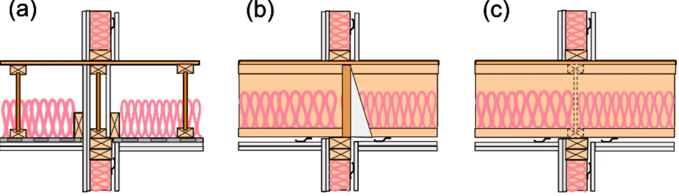
The results in this paper apply to wood-framed constructions, and most of the data were obtained with three wall/floor details illustrated in Figure 2. Each wall had one row of 38 x 89 mm wood studs, with 2 layers of 16 mm gypsum board screwed directly to one side, and one layer of 16 mm gypsum board mounted on the other side using resilient metal channels. All the floors had a sub-floor of 19 mm oriented strand board (OSB) screwed to the top of the 305 mm wood-I joists, 150 mm thick insulation between the joists, and a double layer of 16 mm gypsum board supported below the joists on resilient metal channels. In each case the wall/floor junction included suitable elements to block fire spread via the floor cavity, and the OSB sub-floor sheathing was continuous across the wall/floor junction.
(a)
(b)
(c)
(a)
(b)
(c)
(a)
(b)
(c)
Figure 2: Construction details of three wall/floor systems evaluated. The joists were oriented (a) parallel to the wall, (b) perpendicular to the wall, and (c) with joists continuous across the wall and perpendicular to it.
A smaller series of measurements with the same floor construction and double wood stud walls (2 rows of 38 x 89 mm wood studs with gypsum board screwed to the outside faces) was also performed.
2. RESULTS AND DISCUSSION
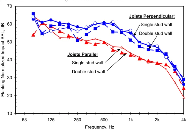
Figure 3 shows the normalized impact sound due to flanking via a single wall in the room below. Clearly the flanking transmission via the wall depends significantly on the joist orientation relative to the wall. However, the difference between single- and double-stud wall framing was small, so an average over the wall-framing cases can reasonably be used to
create an estimate of the flanking for the discussion below. 10 20 30 40 50 60 70 63 125 250 500 1k 2k 4k Frequency, Hz Flanking N o rmalized Impact SPL, dB Joists Parallel
Double stud wall
Single stud wall
Joists Perpendicular: Single stud wall
Double stud wall
Figure 3: Flanking Normalized Impact Sound Pressure Level due to path via a single wall in the room below, with 2 layers of direct-attached gypsum board on the flanking wall, and impact source at 2.2 m from the wall.
To clarify the physics of structure-borne transmission in the wall/floor system, the flanking transmission in Figure 3 was measured with the standard impact source centered at a set of positions 2.2 m from the wall (deliberately deviating from the set of positions distributed over the whole surface as specified in ISO 140-6 and ISO 10848-1). This measurement approach was used as the basic characterization for all the constructions evaluated in this project. These basic measurements were supplemented with tests using other positions for the standard impact source, and with multi-point accelerometer measurements of propagation across the floor, to characterize the vibration transmission for each floor system. This combination of information – which is presented more fully in the detailed report [1] – was used for the analysis presented below.
As shown in preceding papers [4,5] the vibration response is dominated by the direct field in these well-damped constructions, so the vibration energy reaching the wall-floor junction depends on location of the impact source.
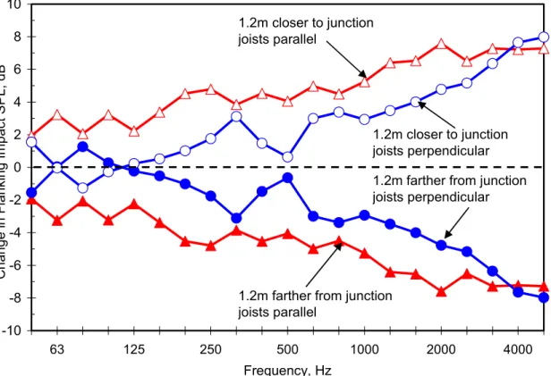
Flanking impact SPL (due to transmission across the floor surface, through the floor/wall junction and into the room below by radiation from the wall) increases as the source moves towards the floor-wall junction, or decreases as it moves away. The change is greater when the floor joists are parallel to the junction because attenuation across the floor is stronger in that direction. This is evident from the results shown in Figure 4.
-10 -8 -6 -4 -2 0 2 4 6 8 10 63 125 250 500 1000 2000 4000 Frequency, Hz C
hange in Flanking Impact SPL, dB
1.2m closer to junction joists parallel
1.2m closer to junction joists perpendicular 1.2m farther from junction joists perpendicular
1.2m farther from junction joists parallel
Figure 4: Change in flanking impact sound pressure level due to via one wall with 2 layers of direct-applied gypsum board, when impact source is moved on the bare OSB floor surface relative to floor-wall junction
Obviously the observed propagation deviates from the simple reverberant field assumption implicit in the EN/ISO 12354 prediction of flanking transmission, and hence one needs a different measurement and calculation approach for localized impact sources on these lightweight framed systems.
Fortunately, a design estimate can be obtained by considering the effect of all paths in the typical situation where the floor is connected to four walls of the room below, so floor joists are parallel to two walls and perpendicular to the other two.
A number of scenarios were evaluated, and it was found that different positions of the impact source on the floor above had little effect on total sound power transmitted by the combination of the four flanking paths.
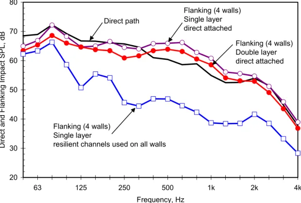
The resulting calculated values for flanking impact SPL due to paths involving all four flanking walls are compared with direct transmission through the floor in Figure 5, for several different treatments of the walls in the room below. The case with a double layer of gypsum board screwed to the framing of all the walls in the room below corresponds to the averaged results presented previously in Figure 3 for a single flanking wall. With a double layer of direct-applied gypsum board on the walls below, the Normalized Impact Sound Pressure Level due to flanking via the four wall paths is quite similar to that for the direct path.
20 30 40 50 60 70 80 63 125 250 500 1k 2k 4k Frequency, Hz D
irect and Flanking Impact SPL, dB
Flanking (4 walls) Single layer direct attached Flanking (4 walls) Double layer direct attached Direct path Flanking (4 walls) Single layer
resilient channels used on all walls
Figure 5: Normalized Impact Sound Pressure Level due to the direct path through the floor-ceiling assembly, or combined flanking paths for all four walls in the room below
With a single layer of gypsum board screwed to the walls, the flanking transmission is even stronger, and dominates the apparent impact sound at the mid frequencies. Mounting the gypsum board on resilient metal channels reduces the flanking transmission by more than 10dB at most frequencies, so the apparent transmission due to all paths would closely approach that for direct transmission. Note that these changes due to the wall treatment should apply for all flanking cases, and not only for the bare subfloor case illustrated above. In addition to the changes that can be achieved by altering the walls in the room below (as shown in Figure 5), one could also modify the impact sound transmission by altering the ceiling or by changing the floor surface in the room above. Obviously using a single layer of gypsum board, or eliminating the resilient support of the ceiling could make things worse, but the case considered is close to the best attenuation for a practical gypsum board ceiling. The remaining option for reducing impact sound transmission is to modify the floor surface, by adding a topping over the basic OSB subfloor, or by adding a floor covering, or by adding both. Changing the floor surface alters impact sound transmission in two ways – changing the power injected into the floor by the impact, and/or altering the transmission across the floor surface to the floor-wall junction. The former affects both direct and flanking transmission, whereas the latter primarily affects the flanking. Hence one must evaluate the changes for both direct and flanking paths.
Three different floor toppings were evaluated with the floor/wall systems presented here: a second 19 mm layer of OSB stapled to the underlying OSB subfloor, a 25 mm layer of gypsum concrete bonded to the subfloor, and a 38 mm layer of gypsum concrete installed over a 9 mm-thick proprietary resilient interlayer.
-30 -25 -20 -15 -10 -5 0 5 10 15 20 25 63 125 250 500 1k 2k 4k Frequency, Hz C
hange in Impact Sound Pressure Level,
dB
Direct
(floor to ceiling)
Flanking (floor to wall below) Joists Parallel to Wall
Flanking (floor to wall below) Joists Perpendicular
Improving Impact Sound Insulation
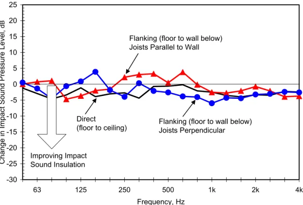
Figure 6: Effect of adding a topping of 19 mm OSB stapled to the subfloor, on the impact sound pressure level due to the direct path or due to one flanking wall.
Changes in impact sound transmission due to adding the OSB topping are shown in Figure 6. Clearly the changes are similar for the direct and flanking paths, but they are not identical. For most frequencies, the topping gives more improvement in the flanking transmission (i.e. – lowers the flanking impact SPL more) when the floor joists are perpendicular to the wall junction, than when they are parallel.
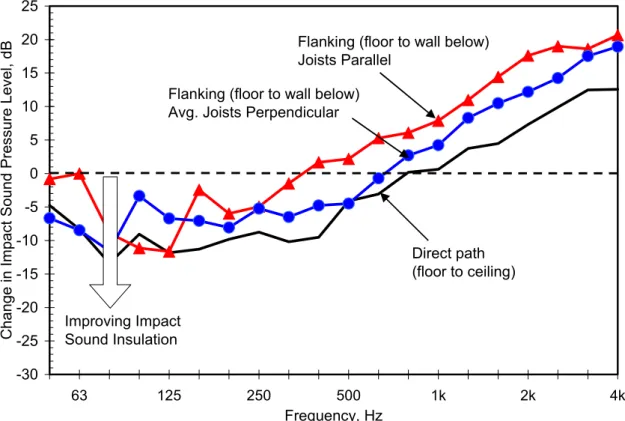
Figure 7 shows a similar trend associated with joist orientation in corresponding changes in impact sound transmission due to adding a 25 mm layer of gypsum concrete bonded to the subfloor. At the lower frequencies, a significant improvement due to the added mass is evident. But for both the direct and flanking paths, the impact sound at higher frequencies is significantly worsened by addition of this topping, because the hard surface of the gypsum concrete increases power transfer from the standard tapping machine.
Adding the bonded gypsum concrete topping also significantly changes vibration propagation across the floor surface (so in Figure 7, the change in direct transmission differs significantly from that for flanking) and the flanking change is different for the two joist orientations. The bonded gypsum concrete topping reduces the significance of the anisotropy due to the joists, so propagation with the topping is similar parallel or perpendicular to the joists [4]. Unfortunately the improved vibration transmission across the floor significantly increases flanking transmission relative to the direct path, especially when the joists are parallel to the wall (because the benefit of this orientation with the bare subfloor is lost).
-30 -25 -20 -15 -10 -5 0 5 10 15 20 25 63 125 250 500 1k 2k 4k Frequency, Hz C
hange in Impact Sound Pressure Level, dB
Flanking (floor to wall below) Joists Parallel
Direct path (floor to ceiling) Flanking (floor to wall below)
Avg. Joists Perpendicular
Improving Impact Sound Insulation
Figure 7: Effect of a topping of 25 mm gypsum concrete bonded to the subfloor, on the impact sound pressure level due to the direct path or due to the flanking path for one wall
-30 -25 -20 -15 -10 -5 0 5 10 15 20 25 63 125 250 500 1k 2k 4k Frequency, Hz C
hange in Impact Sound Pressure Level, dB
Direct path (floor to ceiling) Flanking (floor to wall below)
Joists Perpendicular
Flanking (floor to wall below) Joists Parallel
Improving Impact Sound Insulation
Figure 8: Effect of a topping of 38 mm gypsum concrete over a resilient interlayer, on impact sound pressure level due to the direct path or due to the flanking path for one wall
Figure 8 shows that with a 38 mm layer of gypsum concrete installed over a resilient interlayer, the relative change with joists parallel or perpendicular shows a trend similar to that for other toppings, but the impact levels tend to be lower than with the bonded concrete, especially at the higher frequencies. Again the change is very different for the direct path and the flanking paths.
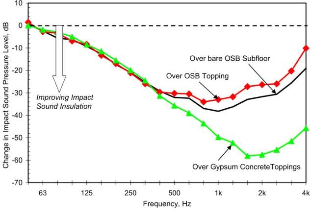
Although the benefit of the heavy gypsum concrete toppings is evident at lower frequencies, the preceding figures exhibit what appears to be a significant worsening of impact transmission at higher frequencies due to the hard surface. This “problem” is largely an artifact of the test situation – in practice some form of covering (such as carpet or vinyl flooring) would be installed over the topping. To assess the practical benefit of adding a floor topping, one should consider the two cases with the same realistic floor covering. To provide a consistent estimate of the effect of floor coverings, impact testing for all floors in this study included measurements with several finishing surfaces. In all cases this included a patch of carpet and a patch of vinyl flooring (see [1] for their properties). Adding these patches provides a reasonable indication of the effect of such limp resilient materials on power injected into the floor by the standard impact source, but does not capture the possible additional effect on the flanking transmission across the floor surface that might be expected with full coverage of the floor. Hence these tend to indicate a lower bound of the improvement that could be expected due to such floor coverings. The incremental effect was sufficiently similar for all paths so the effect could be characterized by an average over the many cases with each kind of topping. Figure 9 shows the average effect for an added carpet, and the corresponding changes due to adding vinyl flooring are given in Figure 10.
-70 -60 -50 -40 -30 -20 -10 0 10 63 125 250 500 1k 2k 4k Frequency, Hz C
hange in Impact Sound Pressure Level, dB
Improving Impact Sound Insulation
Over OSB Topping
Over bare OSB Subfloor
Over Gypsum ConcreteToppings
Figure 9: Change (for direct or flanking paths) due to adding carpet floor covering
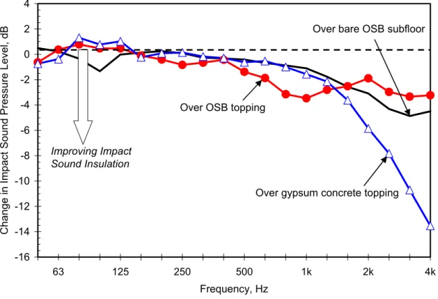
is a greater high frequency improvement when they are applied over gypsum concrete. When the effect of these floor surfaces is included, the increase in high-frequency impact levels with the bare gypsum concrete surfaces is put into perspective as much less of a practical concern, because the single-number impact rating tends to be controlled by the low and mid-frequencies. -16 -14 -12 -10 -8 -6 -4 -2 0 2 4 63 125 250 500 1k 2k 4k Frequency, Hz C
hange in Impact Sound Pressure Level, dB
Over bare OSB subfloor
Over OSB topping
Over gypsum concrete topping
Improving Impact Sound Insulation
Figure 10: Change (for direct or flanking paths) due to adding vinyl floor covering
Note that throughout the presentation of the changes due to wall surfaces, floor toppings, and floor coverings, the incremental effect has not been expressed in terms of single number ratings. These modifications introduce significant changes in frequency dependence of the resulting impact sound pressure level, and those dependences can be quite different for the various direct and flanking paths. Hence single-number ratings should be introduced only at the end of the process, when dealing with the final apparent normalized impact sound pressure level that includes the cumulative incremental effects on all paths.
3. SUMMARY AND/ OR CONCLUSIONS
This paper has illustrated how experimental characterization of the direct and flanking sound transmission paths in wood framed construction can lead to a manageable set of path attenuation terms to represent the effect of specific design tradeoffs. Because of the physical complexities associated with highly-damped orthotropic constructions, the measurement process and the calculations to integrate the effect of the various paths must differ from those of EN/ISO 12354 and ISO 10848-1 (which are based on simpler reverberant field approximations).
Research to date has characterized only a subset of common lightweight framed construction options. Many materials and many construction details were kept constant, to avoid masking
the effect of the systematic modifications. As a result, clear and consistent trends could be associated with specific construction changes, but it must be recognized that the results do not capture the effect of all significant variants. Obviously some variation is to be expected in practice due to substitution of “generic equivalents” or changing specific design details. Despite this caveat, the authors believe that trends shown here do provide a good estimate of the flanking in typical wood-framed constructions, and that a suitable framework for assessment and design has been established.
ACKNOWLEDGEMENTS
The authors gratefully acknowledge the contributions of Ms. Frances King in supervising much of the construction process, and performing many of the experimental measurements. We also acknowledge the support of our industry partners. This paper is a derivative of two industry-sponsored research projects conducted at IRC/NRC where the focus and construction details were decided by a Steering Committee of technical representatives from each of the supporting partners: Canada Mortgage and Housing Corporation (in first phase only), Forintek Canada Corporation, Marriott International, National Research Council Canada, Owens Corning, Trus Joist, and USG Corporation.
REFERENCES
[1] T.R.T. Nightingale, R.E. Halliwell, J.D. Quirt, F. King, Flanking Transmission at the Wall/Floor Junction in Multifamily Dwellings - Quantification and Methods of Suppression, Research Report 168,
Institute for Research in Construction, National Research Council Canada, March 2005
[2] J.D. Quirt, T.R.T. Nightingale, R.E. Halliwell, Guide for Sound Insulation in Wood Frame Construction: Part 1 - Controlling Flanking at the Wall-Floor Junction, Research Report 193, Institute for Research in
Construction, National Research Council Canada, March 2005
[3] R.E. Halliwell, J.D. Quirt, T.R.T. Nightingale, Construction details affecting flanking transmission in wood framed multifamily dwellings, Proc. 31st Inter-noise, Dearborn, USA, 2002
[4] J.D. Quirt, T.R.T. Nightingale, R.E. Halliwell, Controlling flanking transmission due to continuous elements in joist floors," Proc. 32nd Inter-noise, Prague, Czech Republic, 2004
[5] T.R.T. Nightingale, R.E. Halliwell, J.D. Quirt, Vibration response of floors and the effectiveness of toppings to control flanking transmission, Proc. 31st Inter-noise, Dearborn, USA, 2002