Publisher’s version / Version de l'éditeur:
The Journal of Physical Chemistry C, 117, 7, pp. 3527-3536, 2013-01-24
READ THESE TERMS AND CONDITIONS CAREFULLY BEFORE USING THIS WEBSITE.
https://nrc-publications.canada.ca/eng/copyright
Vous avez des questions? Nous pouvons vous aider. Pour communiquer directement avec un auteur, consultez la première page de la revue dans laquelle son article a été publié afin de trouver ses coordonnées. Si vous n’arrivez pas à les repérer, communiquez avec nous à PublicationsArchive-ArchivesPublications@nrc-cnrc.gc.ca.
Questions? Contact the NRC Publications Archive team at
PublicationsArchive-ArchivesPublications@nrc-cnrc.gc.ca. If you wish to email the authors directly, please see the first page of the publication for their contact information.
NRC Publications Archive
Archives des publications du CNRC
This publication could be one of several versions: author’s original, accepted manuscript or the publisher’s version. / La version de cette publication peut être l’une des suivantes : la version prépublication de l’auteur, la version acceptée du manuscrit ou la version de l’éditeur.
For the publisher’s version, please access the DOI link below./ Pour consulter la version de l’éditeur, utilisez le lien DOI ci-dessous.
https://doi.org/10.1021/jp308672a
Access and use of this website and the material on it are subject to the Terms and Conditions set forth at
Thermodynamic and energetic effects on the diameter and defect
density in single-walled carbon nanotube synthesis
Vinten, Phillip; Marshall, Paul; Lefebvre, Jacques; Finnie, Paul
https://publications-cnrc.canada.ca/fra/droits
L’accès à ce site Web et l’utilisation de son contenu sont assujettis aux conditions présentées dans le site LISEZ CES CONDITIONS ATTENTIVEMENT AVANT D’UTILISER CE SITE WEB.
NRC Publications Record / Notice d'Archives des publications de CNRC:
https://nrc-publications.canada.ca/eng/view/object/?id=20076beb-2c24-48ac-a38a-385a2530f2a4 https://publications-cnrc.canada.ca/fra/voir/objet/?id=20076beb-2c24-48ac-a38a-385a2530f2a4
Thermodynamic and Energetic Effects on the Diameter and Defect
Density in Single-Walled Carbon Nanotube Synthesis
Phillip Vinten,
†,‡Paul Marshall,
†Jacques Lefebvre,
†and Paul Finnie*
,†,‡†
National Research Council Canada, Building M-50, 1200 Montreal Road, Ottawa, ON, K1A 0R6, Canada
‡
Department of Physics, University of Ottawa, 150 Louis Pasteur, Ottawa, ON, K1N 6N5, Canada
*
S Supporting InformationABSTRACT: Single-walled carbon nanotube (SWCNT) ensem-bles are characterized by their defect density and diameter distribution. Here, SWCNTs are grown using chemical vapor deposition with acetylene as the carbon source and cobalt as the catalyst and analyzed ex situ, without any modification or processing, using Raman spectroscopy. The defect density shows an activated temperature dependence (activation energy ∼0.8 eV or ∼80 kJ/mol) with fewer defects at high growth temperatures for a wide range of experimental parameters. This is consistent with a single activated mechanism, such as the catalytic healing of defects, possibly a single simple defect. Consistent with previous reports,
we see that low growth temperatures produce smaller diameter SWCNTs than high growth temperatures. Elementary thermodynamic considerations of the strain energy in the lattice constrain the SWCNT diameter distribution and its temperature dependence and appear consistent with our observations. A “phase diagram” for SWCNT growth is constructed and suggests methods of controlling the diameter distribution. There is a trade-off here between small diameter SWCNTs and SWCNTs with low defect densities.
■
INTRODUCTIONFor many applications of single-walled carbon nanotubes (SWCNTs), separation by electronic type, diameter, or chirality is important. There are two general procedures that can lead to SWCNT separation: postgrowth processing or high precision control during synthesis. Postgrowth processing has become very effective (see, for example, ref 1.); however, such separation techniques pose challenges as they typically require solution phase manipulations that usually damage carbon nanotubes (CNTs) and are currently only effective for short (<10 μm) CNTs. Most importantly, postgrowth separation can only be successfully performed on solutions that already contain the desired CNTs, and the yield of the separation techniques will always depend on the initial distribution of CNTs in the sample. Ideally, one would be able to grow CNTs of one single specific chirality. Being able to narrow down the distribution of diameters and chiralities is a step toward this goal. To achieve this greater level of control over the distribution of SWCNTs, the underlying mechanisms that lead to selectivity must be understood.
Much research on the mechanisms that determine SWCNT diameter and chirality has been done,2−12and various models have been proposed. Importantly, the CNT diameter has been shown to depend on the catalyst nanoparticle diameter.3 An kinetic growth rate mechanism based on a screw dislocation derived model has been proposed to explain the distribution of chiralities among SWCNTs.8,12 In the present report, we
highlight the effects of the intrinsic thermodynamic stability of the SWCNT lattice on the diameter distribution.
Defect densities are also a defining characteristic of CNT ensembles, as they are for any crystalline material. The presence of defects alters the optical and electronic properties of CNTs. We find a single common activation energy in the D/G ratio (a measure of the defect density) over a wide range of synthesis conditions and produced CNTs. This observation suggests that the defect density is determined primarily by a single activated mechanism, such as the catalytic healing of defects13−15as the CNT grows. Moreover, as many different types of defects may be present, the single activation energy suggests that the defect density is determined primarily by the healing of a single type of defect, for example, a simple defect, such as a pentagon/ heptagon pair. This has important consequences for the type of material that can be grown.
■
EXPERIMENTAL METHODSThe CNT forests grown here were produced in a cold-walled chemical vapor deposition (CVD) reactor operated at atmospheric pressure, using dilute acetylene16,17 (0.1% C2H2,
99.9% Ar) as the carbon source gas, water vapor18(obtained from a bubbler) and hydrogen gas (2% H2, 98% Ar) as
enhancers, Ar as a carrier gas, and a Co/Al2O3thin film as the
Received: August 31, 2012
Revised: January 21, 2013
Published: January 24, 2013
Article pubs.acs.org/JPCC
catalyst. The catalyst (0.35 nm Co and 50 nm Al2O3layers) is
deposited as uniform layers by e-beam evaporation onto a 0.5 mm thick silicon wafer with a 1 μm thermal oxide that is then cleaved into ∼90 mm2pieces for growth. Upon heating to high
temperatures, the thin Co layer breaks into nanoparticles (with a wide distribution of diameters that is greater than 0.35 nm but does depend on the initial thickness of the layer).19−21 Complete details on the growth procedure can be found in the Supporting Information. Here, we vary both the growth temperature T and the C2H2 partial pressure P (through the
C2H2flow rate F). The entire range of growth temperatures
that produce CNT forests is explored. Outside of this temperature range, either low yield surface CNTs or nothing at all grew. We also analyze previously published data obtained from forests grown using ethanol22and acetylene23as source gases.
Raman spectra were acquired using a custom built Raman spectrometer24with 532 nm excitation. The CNT forests were analyzed ex situ, without any modification or processing, using a 20× objective in plan view, looking orthogonal to the top surface of the forests (parallel to the average CNT axis). All spectra were acquired ex situ at room temperature. For each forest, a minimum of three spectra were acquired, each from a different location on the same forest. Each spectrum consists of five 6 s acquisitions. The power density was kept low enough to prevent burning of the CNTs. We also compare the data acquired in the present report to some of our prior results22,23
that were obtained at both 532 and 785 nm.
■
RESULTS AND DISCUSSIONTypical Raman spectra of our CNT forests, normalized to the G+ peak maximum, are shown in Figure 1. Here, we present
only some of the Raman spectra; additional spectra for all other growth temperatures at 20 °C intervals from 700 to 980 °C are available in the Supporting Information (Figures S1 and S2). From Figure 1, it is clear that the D band intensity (∼1330 cm−1) decreases with increasing growth temperature T,
indicating that the CNTs produced at lower growth temper-atures are more defective.
The Raman spectra also appear to be typical for SWCNT ensembles, with a relatively low D/G ratio and strong and abundant radial breathing modes (RBMs). We, therefore, assume that each RBM is associated with a different diameter SWCNT. This is consistent with the expectation that a sufficiently thin metal catalyst film will favor predominantly SWCNTs, as previously reported for iron.21 As the growth temperature increases, RBMs at smaller Raman shifts appear, while RBMs at larger Raman shifts disappear, indicating that the diameter distribution is shifting toward larger diameters. The G−peaks provide further evidence of the same trend. All of
these changes will now be discussed in detail.
D/G Ratio.The ratio of the D band intensity ID to the G
band intensity IG (the D/G ratio ID/IG) is indicative of the
density of defects in a CNT sample. In the present report, the forests are sufficiently thick that the underlying silicon substrate is generally not visible in the Raman spectra. Because the laser spot size and penetration depth remain constant, the total volume of CNT forest contributing to the Raman signal remains constant, and the D/G ratio provides a meaningful measure of the density of defects.
We calculate the D/G ratio using the integrated intensity of each band obtained from a fitted Lorentzian curve. We observe only a single D band peak and use only the G+ peak for this
calculation (the G+ peak is fitted simultaneously with the G−
peaks). The D/G ratio is plotted in Figure 2 (black circles and
solid black line) as a logarithmic function of 1/kBT, where kBis
the Boltzmann constant. A straight line fitted to the data will thus have a slope that gives a characteristic energy E = 0.82 ± 0.03 eV (79 ± 3 kJ/mol) that describes the relationship ID/IG∝ exp(E/kBT). The proportionality constant is found to be (4 ±
1) × 10−5.
Also plotted on Figure 2 are the D/G ratios from previous reports for ethanol CVD with 0.8 nm of Co catalyst (red),22 acetylene CVD with 0.8 nm of Co catalyst (green),23 and a lower concentration ethanol CVD (10% of the other, but otherwise identical growth conditions) with 0.8 nm of Co
Figure 1. Raman spectra for CNT forest samples with growth temperatures indicated (in °C). Spectra are normalized to 1 at maximum of G band and vertically offset for clarity. Peak labels correspond to Tables 1 and 2.
Figure 2.D/G ratio ID/IGvs 1/kBT for several data sets grown under
different CVD conditions. Fractional defect density fDcalculated from
eq 1. Black circles and solid line are the present data and a linear fit. Other data sets come from our previous reports (see text for details). Broken lines are to guide the eye.
catalyst (blue). The three lines with a positive slope are all parallel to the 0.82 eV line from the present report and provide a good fit to their respective data sets. The negative slope lines (dashed) are to guide the eye and highlight the critical point at which the temperature dependence changes for the ethanol data sets.
Raman spectra for each of the four data sets in Figure 2 are available in the Supporting Information for growth temper-atures of 700 and 900 °C (Figures S3 and S4, respectively). At 700 °C, only the forests grown for the present report (C2H2
carbon source and 0.35 nm of Co catalyst) show a significant number of RBMs (therefore, suggesting a significant number of SWCNTs) and a D/G ratio that is significantly less than 1. At 900 °C, all growth conditions have RBMs and lower D bands. The lack of RBMs on the thick catalyst samples with low growth temperatures suggests that there may be multi-walled carbon nanotubes (MWCNTs) present on these samples.
We previously found a characteristic energy of 1.1 ± 0.1 eV (110 ± 10 kJ/mol) for ethanol CVD.22There are two reasons why this is different from the present characteristic energy of 0.82 ± 0.03 eV (79 ± 3 kJ/mol). First, the ethanol data have a critical point where the dependence on temperature changes and the exact position of this point is not easy to determine. The slope will change based on which points are included in the fit. Second, the scatter in the ethanol data is rather large. The scatter in the present data is much smaller due to more stringent controls on the acquisition of the Raman spectra. In Figure 2, it appears that these two data sets are parallel.
The exact nature of the mechanisms that generate defects is restricted by the data presented in Figure 2. For each data set, the 0.82 eV slope fits the data quite well. This suggests that the mechanism responsible for this temperature dependence is independent of the source gas, concentration, and catalyst thickness/size (though these all affect the value of the D/G ratio through the intercept in Figure 2). Preliminary D/G ratio data obtained from CNT forests grown with Fe catalyst suggest an activated temperature dependence, but with a noticeably lower activation energy (see the Supporting Information, Figure S6). We have previously reported that the kinetics of ethanol growth and acetylene growth differ significantly,22,23 despite the fact that their D/G ratios are similar functions of growth temperature T. The Raman spectra for all four data sets shown in Figure 2 (see the Supporting Information, Figures S3 and S4) differ considerably in terms of CNT species (in particular, SWCNTs vs MWCNTs) and quality, suggesting that the defect density is independent of the material produced. Combined, all of the above observations suggest that the mechanism that determines the defect density is intrinsic to the formation of a graphene lattice.
The fact that a single activation energy is seen across all the data sets suggests that a single mechanism is responsible for our observations. The healing of defects13,15 satisfies the above criteria. Furthermore, the single energy suggests that the healing of a single type of defect may be responsible. We propose that the observed temperature dependence of the D/G ratio is a result of the activated catalytic healing15of one single
type of simple defect, such as a pentagon/heptagon pair. Although many types of defects may form in the CNT lattice and eventually be integrated into the CNT, the defects with the lowest activation energy for healing will be the most readily healed. Higher growth temperatures make this healing process more effective, thus leading to a lower overall density of defects.
In general, defect healing can have an activation energy much higher than the observed 0.82 eV; a simple low-energy pentagon/heptagon pair can have a formation energy of up to 4.4 eV.15The presence of edges, catalytic adatoms, or metal catalyst can lower the energy barrier for healing to values on the order of 1 eV.15,25,26 This mechanism, therefore, depends on the catalytic material used (as suggested by our preliminary Fe investigation), and this dependence would likely be seen in the magnitude of the characteristic energy.15,27
It is also possible that the observed energy (0.82 eV) may be the result of a barrier to carbon surface diffusion. As the temperature increased, more carbon would reach the growth front and potentially lead to fewer defects. The increased rate of carbon diffusion should also lead to an increased growth rate. This explanation appears inconsistent with our data because, in a previous report,23we have observed that the growth rate does not increase with temperature in our C2H2CVD process.
The critical point in the ethanol D/G ratio data sets (see ref 22.) shows that there is a second mechanism for ethanol growth that determines the D/G ratio. This mechanism is likely related to the opening of a new defect production pathway at high growth temperatures that may be related to, for example, the onset of the gas phase pyrolysis of ethanol. The critical point may depend on the catalyst material as well, but seems to be unique to ethanol as it is not observed for acetylene over the entire temperature range.
The D/G ratio can be written as being proportional to the defect density nD, which was determined for graphene to be
(for 532 nm laser excitation)28nD = (2.2 ± 0.6) × 10−3(ID/
IG)peak defects/nm2, where (ID/IG)peak is the ratio of the peak
intensities, instead of the integrated intensities used in the present report. To account for this difference in ID/IG, we
include an extra factor of 0.4 ± 0.1 (see the Supporting Information, Figure S7 and related text). The linear defect density (along the length of an SWCNT of diameter d) is λD=
πdnD, and the fractional defect density (number of defects per
carbon atom) is given by
= Ω = ± × −
fD nD (2.3 0.6) 10 ( / ) defects/carbon5I ID G
(1)
Here, Ω = 0.026 nm2/carbon is the density of graphene. Note
that a single defect may affect many carbon atoms. For an SWCNT with a D/G ratio of 0.1 (which occurs at ∼950 °C), we find fD = 2.3 × 10⁻⁶ defects/carbon (or equivalently 1
defect per 4.4 × 10⁵carbon atoms) and λ
D= 0.28 defects/μm
(for a 1 nm diameter SWCNT). Conversely, this means that it would be possible to grow a 3.6 μm segment of a 1 nm diameter SWCNT without any defects at ∼950 °C.
Here, the linear growth rate for C2H2CVD is on the order of
1 μm/s,23corresponding to 1.2 × 10⁵ carbon/s added to the
CNT (for a 1 nm diameter SWCNT). At this temperature, the D/G ratio is ∼0.3, which is equivalent to fD = 6.9 × 10⁻⁶
defects/carbon. This implies that defects are incorporated into the CNT at a rate of ∼1 defect/s. The actual defect production rate would be at least this high; however, it is more likely that defects are produced at a much higher rate and then healed.
The synthesis of a graphene lattice (and, therefore, CNTs) from C2H2 is thermodynamically spontaneous under
exper-imental conditions up to very high temperatures (∼3000 °C; see below). However, it is commonly observed that temper-atures above ∼550 °C are necessary to grow CNTs in CVD. The defect healing mechanism predicts a minimum temper-ature for growth: at low tempertemper-atures, the lattice is too
The Journal of Physical Chemistry C Article
dx.doi.org/10.1021/jp308672a | J. Phys. Chem. C 2013, 117, 3527−3536
defective to grow. If we assume that a certain defect density is sufficient to prevent growth, we can calculate the minimum temperature required for growth using the results presented in Figure 2. For example, if a defect density of λD= 1 defect/nm in
a 1 nm diameter SWCNT (nD∼ 0.32 defects/nm2and fD∼ 1 defect/120 carbon atoms) is sufficient to prevent growth from occurring, we find a minimum growth temperature T ∼ 200 °C if we extrapolate using the line of best fit in Figure 2.
Here, the observed minimum temperature for CNT growth is ∼660 °C. If defect healing was the mechanism determining this temperature and preventing growth, it would correspond to a much smaller defect density of nD∼ 2.5 × 10⁻⁵defects/nm2 (λD = 8 × 10⁻⁵ defects/nm in a 1 nm diameter SWCNT).
Thus, although the defect healing mechanism does set a minimum temperature for growth, here it is probable that this minimum temperature is determined by a different mechanism, such as a lack of catalyst nanoparticles forming as the temperature becomes too low.19,20
The healing of defects also explains why high growth temperatures produce fewer defects, as the higher temperatures promote an increased healing rate. Above, we calculated that it is possible to produce a 3.6 μm segment of a 1 nm diameter SWCNT without any defects at ∼950 °C. Extrapolating to a slightly higher temperature (∼1200 °C, ID/IG∼ 0.03), it should be possible to produce a 12 μm segment of a defect-free 1 nm diameter SWCNT. At even higher temperatures (∼1500 °C, ID/IG ∼ 0.009), a 40 μm segment of a defect-free 1 nm diameter SWCNT should be possible. Of course, as T increases, other mechanisms, such as gas phase etching, may set in.
Although defects are minimized at high growth temperatures T, here, higher T also have a significantly lower yield (represented by forest height H, as shown in the Supporting Information, Figure S8), thus highlighting a trade-off between the quality and quantity of currently produced CNT forests, as recently reported by Kimura et al.29The trend of forest height H as a function of growth temperature T (see the Supporting Information, Figure S8) for the forests in the present report is consistent with our previous report of acetylene growth.23
Although using a thin catalyst (0.35 nm in the present report) lowered the D/G ratio (see Figure 2), it also decreased the yield. Decreasing the C2H2flow rate F does slightly improve
sample quality, with the D/G ratio changing from 0.3 to 0.2 (at T = 840 °C) as F decreases from 270 to 40 sccm (see spectra in the Supporting Information, Figure S5). Decreasing F likely improves the D/G ratio because the lower flow rate provides a lower growth rate, thus providing more time to heal the defects as the CNT is growing.14,15 Decreasing F does not have a noticeable effect on the yield, but it does significantly lengthen the growth time required to achieve a similar yield, which is an important consideration by itself.
CNT Diameters.The other main trend seen in the Raman spectra (Figure 1) is that the positions of the RBMs shift toward smaller Raman shifts, and thus larger diameter SWCNTs, as the growth temperature T increases. This is commonly observed in many synthesis processes.5,9,11,30−38We identify 10 regular RBMs that consistently show up in our spectra (see Table 1). We calculate the diameters of the associated SWCNTs using the relationship ωRBM= 248/d cm−1
with d in units of nanometers.39
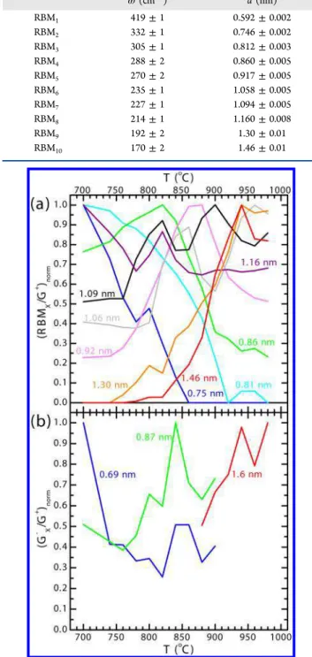
We track the intensity of each RBM as a function of growth temperature T in Figure 3a, which shows the intensity of each RBM relative to G+ (thus normalizing for the amount of
carbon) and then normalized to 1 at its maximum. Relatively,
smaller diameter SWCNTs become less abundant as T increases while the relative abundance of larger diameter SWCNTs increases. RBM1 was consistently very weak, and
meaningful data of this type could not be extracted.
Smaller diameter SWCNTs have their maximum intensity at lower growth temperatures than the larger diameter SWCNTs. As the growth temperature increases, increasingly larger diameter SWCNTs reach their maximum abundance and then decline. It is interesting to note that some curves in Figure 3a (corresponding to 1.06, 1.09, and 1.16 nm SWCNTs) Table 1. Observed RBMs and Calculated Diameters
ω(cm−1) d (nm) RBM1 419 ± 1 0.592 ± 0.002 RBM2 332 ± 1 0.746 ± 0.002 RBM3 305 ± 1 0.812 ± 0.003 RBM4 288 ± 2 0.860 ± 0.005 RBM5 270 ± 2 0.917 ± 0.005 RBM6 235 ± 1 1.058 ± 0.005 RBM7 227 ± 1 1.094 ± 0.005 RBM8 214 ± 1 1.160 ± 0.008 RBM9 192 ± 2 1.30 ± 0.01 RBM10 170 ± 2 1.46 ± 0.01
Figure 3. Relative SWCNT abundance as a function of growth temperature T as determined by (a) RBM intensity and (b) G−
intensity. Intensities relative to G+ intensity and normalized at the
maximum for each curve.
have a double peak. This may arise from unresolved doublets in the RBM spectra. If an RBM was really two (or more) unresolved peaks from slightly different diameter SWCNTs, we might expect that each would reach a maximum abundance at a different temperature.
To further quantify this shift toward larger SWCNT diameters d at higher growth temperatures T, we define an average diameter dav, which is taken as a weighted average of
the RBMs’ peak positions. The weighting is given by the integrated intensity of each RBM relative to the total integrated intensity of all the RBMs. The intensities are determined by fitting the spectra with a series of Lorentzian curves, one for each RBM. This parameter is plotted in Figure 4 (open circles)
and varies from a minimum of 0.94 nm at 700 °C to 1.09 nm at 980 °C. We note that dav is heavily influenced by resonance
effects, and, in particular, the RBMs at 235 and 227 cm−1
(corresponding to 1.06 and 1.09 nm diameter SWCNTs respectively), which are consistently intense.
The minimum observed diameter dmin and maximum
observed diameter dmax can also be determined. From Figure
3a, the 0.75 and 0.81 nm diameter SWCNTs disappear completely as the growth temperature increases, whereas the 1.30 and 1.46 nm diameter SWCNTs appear. Although RBM1
(representing a 0.59 nm diameter SWCNT) is not shown in Figure 3a due to its low signal/noise ratio, it is clearly absent above 820 °C (see the Supporting Information, Figure S2). Using these points, and the overall smallest and largest observed diameters (dashed lines in Figure 4), we can approximate dmin and dmax, which are shown as the triangles
in Figure 4. We see that dav(open circles in Figure 4) seems to
track dminand dmax quite well, and thus provides a reasonable
estimate of the true average.
While the positions of the RBMs are most commonly used to determine SWCNT diameters, the positions of the G−peaks
also depend on the diameter. To supplement the diameter information obtained from the RBMs, we also look at the position of the G−peaks ω
G−. For semiconducting SWCNTs,
this dependence is: ωG−= 1582−27.5/d2cm−1with d in units of
nanometers.40 Due to the sharp line shape and nice fit by a
single Lorentzian, we assume that the G−peaks that we observe
all correspond to semiconducting SWCNTs.39 We identify three strong G− peaks that consistently appear in each
spectrum, and we track these peaks as a function of growth temperature T. The positions of these peaks are given in Table 2, along with their calculated diameters.
As with the RBMs, we track the intensity of each G−peak as
a function of growth temperature T in Figure 3b, which shows the intensity of each G− peak relative to the G+ peak and
normalized at its maximum. The G− results in Figure 3b are
consistent with the RBM results in Figure 3a: smaller diameter SWCNTs become relatively less abundant as the growth temperature increases, whereas larger diameter SWCNTs become relatively more abundant, with the abundance peaking at higher growth temperatures for larger diameter SWCNTs.
Unlike the RBMs, the G− peak data are noisier due to
increased difficulty fitting the peaks on the sloping background, whereas the RBMs had a relatively flat background. Furthermore, the G−peaks are not readily visible throughout
the entire temperature range for this same reason: they become washed out by the background. The peaks visible at lower growth temperatures (G1− and G2−) correspond to smaller
diameter SWCNTs than the peak visible at higher growth temperatures (G3−), which shows a shift to larger diameters at
higher T and is consistent with the results derived from the RBMs.
Finally, the SWCNT diameter dependence on growth temperature can be obtained from the position of the D band ωD, which, at all T, is well fit by a single Lorentzian line
shape. For a single SWCNT, ωDis related to the diameter d:
ωD= ωDo+ C/d cm−1with d in units of nanometers.41Here, ωDo
and C are equal to 1354.8 cm−1 and −16.5 nm/cm,
respectively, for 2.41 eV laser excitation and 1309 cm−1 and
−18.9 nm/cm, respectively, for 1.58 eV laser excitation.41To determine the parameters for 2.33 eV (532 nm) laser excitation, we use linear interpolation and find ωDo = 1351 cm−1and C =
−16.7 nm/cm.
For an ensemble of CNTs, as in the forests of the present report, the observed position and width of the D band depend on the distribution of CNTs in the sample.22,27As the growth temperature increases, we do see a slight shift in the position of the D band, which can be related to a shift in the average diameter of the SWCNTs toward larger diameters. These data are shown in Figure 4 as the solid black line and is consistent with the temperature dependence determined from the RBMs. Thermodynamic Model. The shift to larger diameter SWCNTs with increasing growth temperature T is seen in many different CVD processes using a wide variety of source gases and catalysts.5,9,11,32−35,37,38 Furthermore, such behavior has also been reported in pulsed laser synthesis.30,31Given that these processes vary considerably from one another but all show a similar diameter dependence on temperature, it seems probable that there is a common mechanism that determines the SWCNT diameter distribution and that this mechanism is
Figure 4.Diameter d vs growth temperature T. Broken lines represent the window in which RBMs were observed. RBM derived results are represented by symbols; D band derived results are given by a solid black line. Colored lines are predictions of the thermodynamic model.
Table 2. Observed G−Peaks (for Semiconducting SWCNTs)
and Calculated Diameters
ω(cm−1) d (nm)
G1− 1524 ± 1 0.69 ± 0.01
G2− 1545 ± 1 0.87 ± 0.01
G3− 1571 ± 2 1.6 ± 0.1
The Journal of Physical Chemistry C Article
dx.doi.org/10.1021/jp308672a | J. Phys. Chem. C 2013, 117, 3527−3536
intrinsic to CNT growth, as opposed to being specific to one particular catalyst or source gas.
One potential explanation for the commonly observed diameter dependence is the thermodynamic stability of the CNT lattice4,5,34,42or the cap.43Previous studies have explored
the interactions between the SWCNT cap and the catalyst nanoparticle at the atomic level using models of strain,2 thermodynamic models,44 and simulations.45−48 However, connecting these results directly to CVD process parameters (in particular, source gas pressure and composition) can be challenging. Here, we look at the overall chemistry and thermodynamics of growth in relation to the CVD process parameters (temperature, pressure, and gas composition) and, using a model of this, investigate to what extent the observed temperature dependence of the diameter distribution can be explained by the intrinsic formation thermodynamics of CNTs. For simplicity, we consider only SWCNTs and assume that once one begins growing, its diameter does not change,24,38 though it remains possible that the nanoparticle diameters may change due to Ostwald ripening.49
To understand this intrinsic thermodynamic effect, we suppose that SWCNTs grow using carbon produced in the complete decomposition of the C2H2source gas into graphite
and hydrogen:
⇌ +
C H (gas)2 2 2C(graphite) H (gas)2 (2)
Although this is the overall reaction of the C2H2reactant to the
CNT product, the reaction itself can be broken down into a series of elementary steps, such as those proposed by Eres et al.50and Wirth et al.51However, here we are interested in the overall reaction because we are interested in the overall thermodynamics of the reaction.
A chemical reaction is spontaneous when its change in free energy ΔG = ΔH − TΔS < 0 (ΔH is the enthalpy of formation, and ΔS is the entropy). For the above reaction, the thermodynamic parameters are (per carbon atom produced and in the standard state, designated by “°”) ΔH° = −1.18 eV/ carbon (114 kJ/mol carbon) and ΔS° = −0.305 meV/K/ carbon (29.4 J/K/mol carbon).52 However, in the actual chemical reaction (eq 2), C2H2and H2are not in their standard
states. The effect of the pressure P of the gaseous chemicals alters the change in free energy, ΔG = ΔG° + ΣnikBT ln(Pi/P°),
where the ni are the stoichiometric coefficients (positive for
products and negative for reactants) and “°” denotes the standard state. For the above chemical reaction, this makes the overall change in free energy
Δ = Δ ° − Δ ° − ⎛ ⎝ ⎜⎜ ⎞ ⎠ ⎟⎟ G H T S k T P P 1 2 B ln C H H 2 2 2 (3)
Here, PC2H2= 90 Pa and PH2= 540 Pa. Setting ΔG < 0 in eq 3
means that this reaction (eq 2) is spontaneous up to ∼3000 °C under experimental conditions.
For an SWCNT, the thermodynamic parameters must be adjusted due to the different crystal structure of CNTs. We consider two possibilities involving the strain in the SWCNT: the strain due to rolling the graphene sheet into an SWCNT and the strain in the formation of the CNT cap. We suppose that this strain energy E changes the enthalpy of formation of graphite ΔH° to ΔH° + E. There may also be changes in ΔS°, but we assume that these effects are negligible.
The diameter-dependent curvature induced strain energy E resulting from rolling the graphene lattice into an SWCNT can be written, per carbon atom, as a function of SWCNT diameter d:53,54 = Ω = E Ya d A d 6 3 2 2 (4)
Here, Y = 1 TPa is the elastic modulus and a = 0.34 nm is the interlayer spacing in graphite, suggesting that A = 0.97 eV nm2.
More sophisticated theoretical calculations show the same diameter dependence, but with A = 0.08 eV nm2,54−64which
we will use here.
The strain energy in the SWCNT cap can also be written as a function of SWCNT diameter if one assumes that the SWCNT cap is half of an approximately spherical fullerene with the same diameter as the SWCNT. On a per carbon atom basis, this energy also has the form E = A/d2, where A ∼ 0.22 eV
nm2.57,65,66 This form is only approximately valid for small
fullerenes (d < 1.5 nm),57 but since we are primarily considering SWCNTs with diameters in this range, higher diameter deviations are ignored.
The strain energy has the same form for both the CNT lattice stability and the cap stability. One can understand intuitively that the cap stability has a higher energy scale because its curvature is in two dimensions, whereas the rolling of the CNT takes place in only a single dimension.
Initially, adding new carbon to the SWCNT requires the additional energy (relative to graphite), as shown in eq 4, with A ∼ 0.22 eV nm2. As the length of the nanotube increases toward infinity, this strain energy per carbon atom decreases rapidly as new carbon atoms are added to the SWCNT lattice according to eq 4 with A = 0.08 eV nm2.
The SWCNT cap energy, as shown in eq 4, should also contain some correction terms to account for the fact that, unlike a free-standing fullerene, the half fullerene of the cap interacts with the catalyst nanoparticle. These interactions have previously been shown to be important.2,44−48One correction is an interaction between each carbon atom in the cap and the catalyst nanoparticle. As a first approximation, this is a constant on a per carbon atom basis and should reduce the enthalpy of formation of the cap. The other correction is an interaction between the edge of the cap and the catalyst nanoparticle. This correction depends on the number of carbon atoms around the perimeter of the cap, which is proportional to d. On a per carbon atom basis, this correction is proportional to d−1since
the number of carbon atoms in the cap is proportional to d2.
On the basis of previous reports,45,47,48these corrections may be on the same order of magnitude as the strain energy.
The overall change in free energy for the complete conversion of acetylene into SWCNTs is given by
Δ = Δ ° + − Δ ° − ⎛ ⎝ ⎜⎜ ⎞ ⎠ ⎟⎟ G H A d T S k T P P 1 2 ln 2 B C H H 2 2 2 (5)
To determine the minimum diameter dmin, we set ΔG = 0 in eq
5 and solve for d. The results are presented in Figure 4 as the red and blue solid curves for the cap energy and rolling energy, respectively. The higher growth temperature range (with a logarithmic scale) shows the overall trend.
The model predicts a minimum diameter of 0.52 nm at 700 °C, which increases continuously to 0.56 nm at 980 °C. Experimentally, the observed minimum diameter varies from 0.59 nm at 700 °C to 0.86 nm at 980 °C. Comparing the
models’ predictions to our results, the stability boundary obtained from the SWCNT formation thermodynamics (blue curve in Figure 4) is lower than the experimental data. On the other hand, the stability boundary obtained from cap formation thermodynamics (red curve in Figure 4) is quite close to the experimental values.
The minimum diameter dminas predicted by the
thermody-namics of the SWCNT formation (blue curve in Figure 4) is a firm lower limit on the diameter as it represents the final product of synthesisa free-standing SWCNTand the reaction must lead to this product in the end. The thermodynamics of the cap formation, as plotted in Figure 4 (red curve), represent a tighter constraint on dmin. If the
above-mentioned corrections to the enthalpy of formation of the SWCNT cap result in a cap that is more thermodynamically stable than an SWCNT of a given diameter (in Figure 4, this corresponds to the red curve being lower than the blue curve), this would lead to the situation where a small diameter cap could form, but an SWCNT could not grow. In this case, dmin
for the produced SWCNTs would necessarily be determined by the thermodynamics of the SWCNT formation (blue curve).
The deviation between predicted and observed minimum diameters is not surprising. First, Raman spectroscopy is a resonant process; it only probes a subset of the SWCNTs present in the sample. The minimum diameter, as measured with Raman spectroscopy, is thus only accurate so long as the smallest diameter in the distribution happens to be in resonance. With only one excitation wavelength, we extract a very rough dminand dmaxwith steplike features larger than the
spacing of subsequent diameters. Second, the actual situation during growth is more complex than presented in the model. For example, the interaction between the edge of the cap and the catalyst nanoparticle should also influence the chirality.67
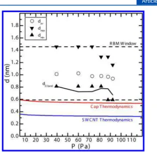
This model predicts a dependence on the partial pressure of C2H2, P. We test this by varying the C2H2flow rate F (at T =
840 °C) while keeping the other flow rates fixed, thus varying the partial pressure of C2H2. Following the same procedure
used to analyze the temperature dependence, we do find a change in davas a function of pressure: a decrease from 1.01 to
0.94 nm as the pressure is increased from 39 to 92 Pa, which is shown in Figure 5 as open circles. The minimum diameter dmin
and maximum diameter dmaxare shown as triangles, along with
the average diameter as determined from the D band (solid black line) and the theoretical curves (red for cap energy and blue for rolling energy). The dependence of the SWCNT diameter on pressure has been reported by others.7,11,68−70Raw spectra can be found in the Supporting Information (Figure S5). The model fits the data as well as it does in Figure 4. Here, the trends are more subtle, but that too is predicted by our model.
Because eq 5 relates the growth temperature T and C2H2
pressure P, one can construct a “phase diagram” that describes the spontaneity of SWCNT growth. This “phase diagram” is shown in Figure 6 using A = 0.22 eV nm2and P
H2= 540 Pa.
SWCNT diameters are only thermodynamically favorable above the indicated lines. In general terms, in order for the formation of very narrow CNTs from C2H2to be energetically
favored, one requires either high pressure P or low growth temperature T.
Our data also indicated a maximum diameter dmaxthat varied
as a function of T. We now consider the origin of dmax. In order
for CNT to grow, the lattice, as it forms on the catalyst
nanoparticle, must “lift off” from the nanoparticle and break free from the adhesion energy holding it there.2,45−48 This adhesion energy is otherwise a barrier to growth. It has been shown previously that this adhesion energy is comparable to the cap formation energy.45 Larger diameter caps have more carbon atoms, and thus greater total adhesion energy. As the growth temperature increases, larger caps are able to lift off, thus producing larger diameter SWCNTs. This may explain the observed temperature dependence of the maximum diameter.
Finally, we outline how our thermodynamic model can be applied to other synthesis processes. Most importantly, the chemical reaction involved in growth must be known, as is shown here for C2H2in eq 2. The pressures of the gases can
also be very important because the temperature dependence of dmincomes from the term ΔS = ΔS° − ΣnikBln(Pi/P°), where
ΔS is the real entropy (corrected for nonstandard conditions) and the ni are the stoichiometric coefficients (positive for products and negative for reactants). Here, the pressure
Figure 5.Diameter d vs C2H2pressure P. Broken lines represent the
window in which RBMs were observed. RBM derived results are represented by symbols; D band derived results are given by a solid black line. Colored lines are predictions of the thermodynamic model.
Figure 6.SWCNT “phase diagram” for cap stability. A given diameter SWCNT is stable above the line representing its diameter. This figure assumes a C2H2 carbon source and uses thermodynamic parameters
from the text.
The Journal of Physical Chemistry C Article
dx.doi.org/10.1021/jp308672a | J. Phys. Chem. C 2013, 117, 3527−3536
correction term is small; however, for other carbon sources, it may be large enough to change the sign of ΔS, and thus drastically alter the temperature dependence of dmin.
Different carbon sources can yield different trends, depend-ing on the signs of ΔH° and ΔS (four possible cases exist; see the Supporting Information for further details). As an example, CNT growth from CO has a well-known chemical reaction (disproportionation of CO),68and our thermodynamic model can thus be applied. The predicted trend for CNT growth from CO as a carbon source is qualitatively similar to that for C2H2,
and is generally consistent with experimental results for the temperature dependence9,33,37and pressure dependence68,69of dmin. For the case of ethanol, the chemical reaction that leads to
growth is not as certain. One of the possible reactions is the complete decomposition of ethanol:
⇌ +
+
CH CH OH(gas) 2C(graphite) 2H (gas) H O(gas)
3 2 2
2 (6)
This reaction has a change in entropy ΔS with the opposite sign (compared to C2H2 and CO), and we find that dmin is
predicted to decrease with increasing T (see the Supporting Information). Our own ethanol data (see ref 22.) is not sufficiently clear to extract dminas a function of T; however, the
predicted temperature dependence is contrary to other published results5,11,32,34 that show that dmin increases with
increasing T, like the C2H2 data in the present report. This
difference may be a result of a different mechanism determining dminby setting conditions on growth that are more strict (see
the following section on “growth filters”). Furthermore, the above chemical reaction may not be the reaction that leads to growth (and thus determines the diameter). Regardless, whatever reaction does lead to growth (whether or not dmin
is determined by thermodynamics or another mechanism that is more strict), only CNTs that are thermodynamically favorable can grow.
Growth Filters. Other mechanisms do contribute to determining the diameter distribution of SWCNTs. The most prominent of these mechanisms involves the catalyst nano-particle, which is known to affect the diameter of the CNTs that they produce.3 Mechanisms that alter the catalyst nanoparticle shape or diameter distribution thus likely alter the diameter distribution of the grown SWCNTs as well. The “phase diagram” in Figure 6 alone cannot determine the diameters of the SWCNTs that would be produced in a synthesis process. In order for any CNTs to grow, all mechanisms would need to be “properly aligned” in the sense that they must all allow for the formation of CNTs in the same diameter range.
Another way of looking at this is to consider that the observed diameter distribution is the result of a series of “filters” through which all diameters are sorted. In general, the abundance of different CNTs is a result of nucleation, growth, and termination. Each of these three stages represents a very coarse filter. Here, we can go one step further and look at some of the mechanisms involved in each of these coarse steps, each of which includes thermodynamic filters and kinetic filters. For a given species of SWCNT (as defined by its chirality (n,m)) to appear in the final synthesized material, it must be able to pass through each of these different filters.
The nucleation filter can be split up: the formation of each (n,m) SWCNT and its cap must be thermodynamically favorable, as shown in the “phase diagram” in Figure 6. This
requires the appropriate combination of growth temperature and gas pressures. Additionally, the size distribution of the catalyst nanoparticles must allow for the growth of each (n,m), whether this is an effect of size, shape, or chemical state of the nanoparticles. Finally, nucleation must occur at an appreciable kinetic rate for each (n,m).
Like the nucleation filter, the growth stage must also be thermodynamically favorable for each (n,m), as well as kinetically favorable for each (n,m) because the SWCNTs must grow at an appreciable rate. One kinetic filter during this stage may include mechanisms such as the screw dislocation growth theory that favors high chiral angles.8,12 Finally, termination must not occur too quickly for each (n,m) or growth will be limited. One consideration for termination is the effect of neighboring CNTs, which is especially important in CNT forest growth. If the CNTs are all growing at vastly different rates, there will be significant strain in the forest, and this may bring about termination.23,71Any (n,m) SWCNT that passes through all of these filters will be observed in the final product. The complete “misalignment” of any of these filters would be sufficient to prevent the growth of CNTs altogether. One potential general way to produce a limited selection of SWCNT diameters can be proposed based on the above discussion by considering two of the filters that occur during nucleation: the thermodynamics of cap formation and the effect of the catalyst nanoparticles, assuming that the nanoparticles can set a well-defined maximum and minimum diameter for the SWCNTs that they produce. First, one must set the properties of the catalyst nanoparticle (size, shape, and chemical composition), thus setting a maximum and minimum allowable SWCNT diameter with this filter. Although the size of the catalyst nanoparticles is affected by the temperature, the size can also be controlled during the catalyst preparation stage. The growth temperature T can then be tuned, thus setting a minimum (and maximum) thermodynamically allowed diam-eter with this filter. By properly adjusting the minimum and maximum diameters allowed by each filter, it should be possible to adjust the overlap and thus narrow the diameter distribution.
■
CONCLUSIONUsing Raman spectroscopy, we have analyzed the relative density of defects in our CVD grown CNTs. High growth temperatures favor large diameter SWCNTs with few defects, whereas lower temperatures favor much narrower SWCNTs, but with more defects. We also see not only a trade-off between the quality and quantity of the SWCNTs29but also a trade-off in terms of their diameter. The similarities of these results to other CVD processes suggest several constraints on the mechanisms responsible for the production of defects, and, in particular, that this mechanism may be intrinsic to the growth of not just a CNT, but a graphene lattice in general. We propose the healing of defects, in particular a single type of simple defect, such as a pentagon/heptagon pair, as the CNTs grow as a possible mechanism to explain the observed temperature dependence of the defect density.
We have shown that there are clear systematic and reproducible changes in the distribution of SWCNT diameters as a function of growth temperature and C2H2pressure in our
CVD process. The diameter-dependent effect of strain induced curvature energy of the bending of the graphene lattice into a CNT and the strain energy of the CNT cap are proposed thermodynamic “growth filters” and may explain our observations. The “phase diagram” for C2H2synthesis suggests
that small diameter SWCNTs are favored at low growth temperatures and high pressures. The overall diameter distribution is determined by several “growth filters”, including the intrinsic thermodynamics mechanism discussed here. For growth to occur, all of these mechanisms must allow a common subset of CNTs. This provides guidelines for the controlled synthesis of SWCNTs with specific diameter distributions.
■
ASSOCIATED CONTENT*
S Supporting InformationThe Supporting Information includes details of the exper-imental procedure for CNT growth, Raman spectra for CNT forests under a variety of growth conditions, and, in particular, functions of growth temperature T and C2H2partial pressure P.
It also includes the D/G ratio temperature dependence for Fe catalyst and the relationship between D/G ratio when calculated using peak intensities versus integrated intensities. Finally, there is a discussion of general cases of the thermodynamic model for dmin with examples. This material
is available free of charge via the Internet at http://pubs.acs.org.
■
AUTHOR INFORMATIONCorresponding Author
*E-mail: Paul.Finnie@nrc-cnrc.gc.ca.
Notes
The authors declare no competing financial interest.
■
ACKNOWLEDGMENTSThe authors thank the referees for their useful and insightful suggestions. The authors also thank the following individuals for their assistance and support: A. Li-Pook-Than, C. Kingston, H. Tran, and M. Denhoff. P.V. was supported by NSERC, NRC-GSSSP, and P.F.’s NSERC Discovery Grant.
■
REFERENCES(1) Hersam, M. C. Nat. Nanotechnol. 2008, 3, 387−394.
(2) Kanzow, H.; Lenski, C.; Ding, A. Phys. Rev. B 2001, 63, 125402. (3) Cheung, C. L.; Kurtz, A.; Park, H.; Lieber, C. M. J. Phys. Chem. B 2002, 106, 2429−2433.
(4) Bachilo, S. M.; Balzano, L.; Herrera, J. E.; Pompeo, F.; Resasco, D. E.; Weisman, R. B. J. Am. Chem. Soc. 2003, 125, 11186−11187.
(5) Miyauchi, Y.; Chiashi, S.; Murakami, Y.; Hayashida, Y.; Maruyama, S. Chem. Phys. Lett. 2004, 387, 198−203.
(6) Lin, M.; Tan, J. P. Y.; Boothroyd, C.; Loh, K. P.; Tok, E. S.; Foo, Y.-L. Nano Lett. 2006, 6, 449−452.
(7) Lu, C.; Liu, J. J. Phys. Chem. B 2006, 110, 20254−20257. (8) Ding, F.; Harutyunyan, A. R.; Yakobson, B. I. Proc. Nat. Acad. Sci.
U.S.A. 2009, 106, 2506−2509.
(9) Li, N.; Wang, X.; Ren, F.; Haller, G. L.; Pfefferle, L. D. J. Phys.
Chem. C 2009, 113, 10070−10078.
(10) Chiang, W.-H.; Sankaran, R. M. Nat. Mater. 2009, 8, 882−886. (11) Picher, M.; Anglaret, E.; Arenal, R.; Jourdain, V. ACS Nano 2011, 5, 2118−2125.
(12) Rao, R.; Liptak, D.; Cherukuri, T.; Yakobson, B. I.; Maruyama, B. Nat. Mater. 2012, 11, 213−216.
(13) Picher, M.; Anglaret, E.; Arenal, R.; Jourdain, V. Nano Lett. 2009, 9, 542−547.
(14) Page, A. J.; Ohta, Y.; Okamoto, Y.; Irle, S.; Morokuma, K. J.
Phys. Chem. C 2009, 113, 20198−20207.
(15) Yuan, Q.; Xu, Z.; Yakobson, B. I.; Ding, F. Phys. Rev. Lett. 2012,
108, 245505.
(16) Eres, G.; Puretzky, A. A.; Geohegan, D. B.; Cui, H. Appl. Phys.
Lett. 2004, 84, 1759−1761.
(17) Eres, G.; Kinkhabwala, A. A.; Cui, H.; Geohegan, D. B.; Puretzky, A. A.; Lowndes, D. H. J. Phys. Chem. B 2005, 109, 16684− 16694.
(18) Hata, K.; Futaba, D. N.; Mizuno, K.; Namai, T.; Yumura, M.; Iijima, S. Science 2004, 306, 1362−1364.
(19) Chhowalla, M.; Teo, K. B. K.; Ducati, C.; Rupesinghe, N. L.; Amaratunga, G. A. J.; Ferrari, A. C.; Roy, D.; Robertson, J.; Milne, W. I. J. Appl. Phys. 2001, 90, 5308−5317.
(20) Takagi, D.; Homma, Y.; Kobayashi, Y. Physica E 2004, 24, 1−5. (21) Zhao, B.; Futaba, D. N.; Yasuda, S.; Akoshima, M.; Yamada, T.; Hata, K. ACS Nano 2008, 3, 108−114.
(22) Vinten, P.; Lefebvre, J.; Finnie, P. Chem. Phys. Lett. 2009, 469, 293−297.
(23) Vinten, P.; Marshall, P.; Lefebvre, J.; Finnie, P. Nanotechnology 2010, 21, 035603.
(24) Finnie, P.; Li-Pook-Than, A.; Lefebvre, J. Nano Res. 2009, 2, 783−792.
(25) Ewels, C. P.; Heggie, M. I.; Briddon, P. R. Chem. Phys. Lett. 2002, 351, 178−182.
(26) Karoui, S.; Amara, H.; Bichara, C.; Ducastelle, F. ACS Nano 2010, 4, 6114−6120.
(27) Picher, M.; Navas, H.; Arenal, R.; Quesnel, E.; Anglaret, E.; Jourdain, V. Carbon 2012, 50, 2407−2416.
(28) Cançado, L. G.; Jorio, A.; Martins Ferreira, E. H.; Stavale, F.; Achete, C. A.; Capaz, R. B.; Moutinho, M. V. O.; Lombardo, A.; Kulmala, T. S.; Ferrari, A. C. Nano Lett. 2011, 11, 3190−3196.
(29) Kimura, H.; Futaba, D. N.; Yumura, M.; Hata, K. J. Am. Chem.
Soc. 2012, 134, 9219−9224.
(30) Bandow, S.; Asaka, S.; Saito, Y.; Rao, A. M.; Grigorian, L.; Richter, E.; Eklund, P. C. Phys. Rev. Lett. 1998, 80, 3779−3782.
(31) Kataura, H.; Kumazawa, Y.; Maniwa, Y.; Ohtsuka, Y.; Sen, R.; Suzuki, S.; Achiba, Y. Carbon 2000, 38, 1691−1697.
(32) Maruyama, S.; Kojima, R.; Miyauchi, Y.; Chiashi, S.; Kohno, M.
Chem. Phys. Lett. 2002, 360, 229−234.
(33) Alvarez, W. E.; Pompeo, F.; Herrera, J. E.; Balzano, L.; Resasco, D. E. Chem. Mater. 2002, 14, 1853−1858.
(34) Unalan, H. E.; Chhowalla, M. Nanotechnology 2005, 16, 2153− 2163.
(35) Ago, H.; Imamura, S.; Okazaki, T.; Saito, T.; Yumura, M.; Tsuji, M. J. Phys. Chem. B 2005, 109, 10035−10041.
(36) Ishigami, N.; Ago, H.; Imamoto, K.; Tsuji, M.; Iakoubovskii, K.; Minami, N. J. Am. Chem. Soc. 2008, 130, 9918−9924.
(37) Loebick, C. Z.; Abanulo, D.; Majewska, M.; Haller, G. L.; Pfefferle, L. D. Appl. Catal., A 2010, 374, 213−220.
(38) Li-Pook-Than, A.; Lefebvre, J.; Finnie, P. J. Phys. Chem. C 2010,
114, 11018−11025.
(39) Dresselhaus, M. S.; Dresselhaus, G.; Saito, R.; Jorio, A. New J.
Phys. 2003, 5, 139.1−139.17.
(40) Telg, H.; Duque, J. G.; Staiger, M.; Tu, X.; Hennrich, F.; Kappes, M. M.; Zheng, M.; Maultzsch, J.; Thomsen, C.; Doorn, S. K.
ACS Nano 2012, 6, 904−911.
(41) Souza Filho, A. G.; Jorio, A.; Samsonidze, G. G.; Dresselhaus, G.; Pimenta, M. A.; Dresselhaus, M. S.; Swan, A. K.; Ünlü, M. S.; Goldberg, B. B.; Saito, R. Phys. Rev. B 2003, 67, 035427.
(42) Inoue, S.; Kikuchi, Y. Chem. Phys. Lett. 2005, 410, 209−212. (43) Reich, S.; Li, L.; Robertson, J. Phys. Rev. B 2005, 72, 165423. (44) Kuznetsov, V. L.; Usoltseva, A. N.; Chuvilin, A. L.; Obraztsova, E. D.; Bonard, J.-M. Phys. Rev. B 2001, 64, 235401.
(45) Ding, F.; Larsson, P.; Larsson, A.; Ahuja, R.; Duan, H.; Rosén, A.; Bolton, K. Nano Lett. 2008, 8, 463−468.
(46) Amara, H.; Bichara, C.; Ducastelle, F. Phys. Rev. Lett. 2008, 100, 056105.
(47) Burgos, J. C.; Reyna, H.; Yakobson, B. I.; Balbuena, P. B. J. Phys.
Chem. C 2010, 114, 6952−6958.
(48) Burgos, J. C.; Jones, E.; Balbuena, P. B. J. Phys. Chem. C 2011,
115, 7668−7675.
(49) Amama, P. B.; Pint, C. L.; McJilton, L.; Kim, S. M.; Stach, E. A.; Murray, P. T.; Hauge, R. H.; Maruyama, B. Nano Lett. 2009, 9, 44−49. The Journal of Physical Chemistry C Article
dx.doi.org/10.1021/jp308672a | J. Phys. Chem. C 2013, 117, 3527−3536
(50) Eres, G.; Rouleau, C. M.; Yoon, M.; Puretzky, A. A.; Jackson, J. J.; Geohegan, D. B. J. Phys. Chem. C 2009, 113, 15484−15491.
(51) Wirth, C. T.; Zhang, C.; Zhong, G.; Hofmann, S.; Robertson, J.
ACS Nano 2009, 3, 3560−3566.
(52) Haynes, W. M., Ed. CRC Handbook of Chemistry and Physics, 91st ed. (Internet Version 2011); CRC Press/Taylor and Francis: Boca Raton, FL, 2011; pp 5.4−5.42.
(53) Tibbetts, G. G. J. Cryst. Growth 1984, 66, 632−638.
(54) Robertson, D. H.; Brenner, D. W.; Mintmire, J. W. Phys. Rev. B 1992, 45, 12592−12595.
(55) Hernández, E.; Goze, C.; Bernier, P.; Rubio, A. Appl. Phys. A:
Mater. Sci. Process. 1999, 68, 287−292.
(56) Sánchez-Portal, D.; Artacho, E.; Soler, J. M.; Rubio, A.; Ordejón, P. Phys. Rev. B 1999, 59, 12678−12688.
(57) Park, N.; Lee, K.; Han, S.; Yu, J.; Ihm, J. Phys. Rev. B 2002, 65, 121405.
(58) Gülseren, O.; Yildirim, T.; Ciraci, S. Phys. Rev. B 2002, 65, 153405.
(59) Cabria, I.; Mintmire, J. W.; White, C. T. Phys. Rev. B 2003, 67, 121406.
(60) Peralta-Inga, Z.; Boyd, S.; Murray, J. S.; O’Connor, C. J.; Politzer, P. Struct. Chem. 2003, 14, 431−443.
(61) Popov, V. New J. Phys. 2004, 6, 1−17.
(62) Barnard, A. S.; Snook, I. K. J. Chem. Phys. 2004, 120, 3817− 3821.
(63) Xiao, C.; Chan, H. S. O.; Xu, G. Q.; Lim, K. T.; Lin, J. Appl.
Phys. Lett. 2004, 84, 1677−1679.
(64) Li, Y.; Peng, S.; Mann, D.; Cao, J.; Tu, R.; Cho, K. J.; Dai, H. J.
Phys. Chem. B 2005, 109, 6968−6971.
(65) Adams, G. B.; Sankey, O. F.; Page, J. B.; O’Keeffe, M.; Drabold, D. A. Science 1992, 256, 1792−1795.
(66) Barnard, A. S.; Russo, S. P.; Snook, I. K. J. Chem. Phys. 2003,
118, 1594−1597.
(67) Liu, Y.; Dobrinsky, A.; Yakobson, B. I. Phys. Rev. Lett. 2010, 105, 235502.
(68) Nikolaev, P.; Bronikowski, M. J.; Bradley, R. K.; Rohmund, F.; Colbert, D. T.; Smith, K. A.; Smalley, R. E. Chem. Phys. Lett. 1999, 313, 91−97.
(69) Carver, R. L.; Peng, H.; Sadana, A. K.; Nikolaev, P.; Arepalli, S.; Scott, C. D.; Billups, W. E.; Hauge, R. H.; Smalley, R. E. J. Nanosci.
Nanotechnol. 2005, 5, 1035−1040.
(70) Wang, B.; Wei, L.; Yao, L.; Li, L.-J.; Yang, Y.; Chen, Y. J. Phys.
Chem. C 2007, 111, 14612−14616.
(71) Han, J.-H.; Graff, R. A.; Welch, B.; Marsh, C. P.; Franks, R.; Strano, M. S. ACS Nano 2008, 2, 53−60.