ARCHITECTURAL PROPERTIES OF A STRUCTURAL THEME: A THEMATIC EXPLORATION
by
Sing-Charn Wong
Bachelor of Arts in Architectural Studies Iowa State University
Ames, Iowa June, 1983
Submitted to the Department of Architecture in Partial Fulfillment of the Requirements for the
Degree of Master of Architecture at the
Massachusetts Institute of Technology June, 1986
QSing Charn Wong 198G
The author hereby grants to MIT
permission to reproduce and to distribute publicly copies of this thesis document Mn whole or in part
Signature of Author_
Certified by
Sing- lrn Wong, Depar9nt of Architecture
February 24,1986 N. Joh Habraken, Thesis Supervisor
ilrofessor of Architecture Accepted by
ABSTRACT
ARCHITECTURAL PROPERTIES OF A STRUCTURAL THEME: A THEMATIC EXPLORATION
by
Sing-Charn Wong
Submitted to the Department of Architecture
on February 24, 1986,
in partial fulfillment of the requirements for the degree of Master of Architecture.
Abstract
The first objective of the thesis is to demonstrate a way of "designing" that comes as much from the forms at hand as from any outside criteria. It involves the establisment of a structural theme and the understanding of its architectural properties. The approach seeks the devel6pment of alternative interpretations within the structural
theme. There is, however, neither context nor program to choose alternatives in. There is only the thematic
development. The structural theme is pushed along, not with the objective to come to a completed " design " but with the objective to pass a variety of stages needed for a demonstration of the method involved. The second objective of the thesis is to explore the ways a structural theme can be communicated.
There are two parts to the study:
1. Part one of the study involves the formulation of the structural system. It also illustrates the design process
of the structural elements. Rules are formulated for the elements by means of a grid position which will, therefore, allow the exploration of the horizontal and vertical relations among elements in the system.
2. Part two of the study demonstrates the deployment of the system. It includes the principles of horizontal
ACKNOWLEDGEMENT
I would like to express my sincerest gratitudes to my advisor,
Professor John Habraken for his invaluable guidance, understanding, patience, and thought-provoking and insightful advice. I would also
like to thank Reinhard Goethert for his constructive criticisms. I am
most indebted to my family : Mama and Papa, Wing-Fat and Li-Ching, Chiu and Li-Kit, Shing-Wei and Men-Shang, Chung-Por and Li-Ming, Kwei-Kun and Li-Cheung, Woo-Kit and Li-Wan, and Shing-Yiu for their invaluable, sacrificial, continuous support. My gratitude towards them is beyond the means of expression. I am also very grateful to all my brothers and sisters in Christ, especially Tom and Lisa Lam, for their prayers and spiritual support. And finally, I want to especially thank my wife, Dilys, for her devotion, understanding, patience and love.
TABLE OF CONTENTS A b stra c t ... i A ck n ow led gem en ts ... 11 T a b le o f C o n ten ts ... iii Chapter I PART ONE Chapter I Chapter I Chapter I PART TWO Chapter I Chapter I Chapter I Chapter I Chapter I In tro d u ctio n ... ... 1 S' I II V D V VI] VI]
X
STEMP rim ary System ...
Secondary System ... ...
F a ca d e ...
EPLOYMENT
Principles of Horizontal Deploymnet - Building Scale ... Principles of Vertical Deploymnet - Building Scale ...
[ Fields - Tissue Scale ...
I Change of Elements in the System ...
C on clu sio n ... 1
Sum m ary of C ontents... ... 103
B ib liograp hy ... 109 12 52 70 75 86 93 96 01
I.
INTRODUCTIONI first learned about the idea of thematic design in
a course taught by Professor John Habraken in the fall
semester of 1984. Since then the idea of designing with
r.
a.theme intrigued me. In the spring semester of 1985,1was writing my thesis proposal and was also working on a project involving mixed-use building for my final stu-dio in the spring program. The stustu-dio was again taught
by John. We began the project by designing our own set
of thematic structural elements which would finally be-come the theme of our building. I started out with the idea of a community type environment that included a large working space flanked by small offices. This idea later generated into a two-story high primary space with secondary floors built inside (figure 1.1). One impor-tant idea about designing the spaces in this project was that they could be changed according to the duration and the nature of the activities. How to design spaces which were capable to 1) accomodate changes and 2)not be neutral but inviting interpretation activities became a challenge to me. The idea of a structural theme includ-ing a primary and a secondary system seemed promisinclud-ing in giving this challenge an answer. A little bit of that answer had already started to show in the design project
I. INTRODUCTION
This thesis is a continuation of that project. The goal is not to further the design but to understand bet-ter the idea of structural theme and the process of for-mulating such a theme as well as to exlore its properties. The portal system, first introduced in my studio project,
is the subject of analysis. The first objective of the
the-sis is to demonstrate a way of "designing" that comes as much from the forms at, hand as from any outside crite-ria. The approach seeks the development of alternative interpretations within the structural theme. There is, however, neither context, nor program to choose alter-natives in. There is only the thematic development. The structural theme is pushed along, not with the ob-jective to come to a completed " design " but with the
objective to pass a variety of stages needed for a demon-stration of the method involved. The second objective of the thesis is to explore the ways a structural theme can be communicated.
I. INTRODUCTION
The drawings in the following pages are extracted from the studio project I did the past semester. This is a multi-use building at Massachusetts Avenue in Cam-bridge, all-purpose work space for the MIT museum and retail space on the ground floor.
I. INTRODUCTION Ik ra e g 1a04e04O)W E3 c1 M tJ C 0 S1-- I-4 - M maCDt0. .1
I
I
________________________________J
iR
1
I
I
'T3..4t:*-mort.- -5ro9>y an171I. INTRODUCTION
GjL
1
0
FI
I
L
II.
PRIMARY SYSTEM11.1
ElementsThe primary system basically consists of 1. vertical structural elements : portals (including structures on top of the portal to support the floor decks) and columns, and 2. horizontal structural elements : girders, beams, and floor decks.
II. PRIMARY SYSTEM
11.1.1 Portal
The main role of the portals is to support the girders as well as the floor decks. They also act as the element to resist external forces along the beam direction.
11.1.2 Girder/Portal
The girders are supported directly by the portals. The diagrams illustarate the structural configuration of the girders related to the portal viewed from the front (fig 11.1.2.1), the side (fig
11.1.2.2), and the top (fig 11.1.2.3), as well as the
symbolic structural diagram (fig 11.1.2.4).
11.1.3 Beam/Girder/Portal
The beams are spanned directly between gird-
'-.-I9I
7l-F
ers.
11.1.4 Floor/Beam/Girder/Portal
The floor decks are spanned directly between j./4 portals within the row of portals or between beams outside the row of portals.
11.1.5 Column/Floor/Beam/Girder/Portal
There are two types of columns. One type
is designed to be placed on top of the portal and j/g
the other type is not.
11.1.6 Shear Wall
Shear walls are occasionally placed along the girder direction to resist lateral forces.
T-Ti
Io
H=-==
-H.=
H
.... .---- -II.1 Elements,II. PRIMARY SYSTEM
11.2.1 Purpose of the position grid At this point, a system is chosen and a
catalogue of elements is formed. The next step is to create a field by these elements. However, before this can be accomplished, the details of the joints between elements and the range of sizes of the elements must be determined. We shall discuss how this can be decided in detail in the following chap-ter. Once the details of the joints and the range of sized of elements are determined, they should be kept constant aferward. This implies that the relative position of the ele-ments should not be changed. A grid should be introduced at this stage to help relating the position of elements.
By means of a grid position, rules can
be formulated for elements. It allows the structural elements to be deployed in contin-uous fields according to the predertermined rules without repetiton. Moreover, the de-ployment of structural elements can be in-terpreted in terms of dimensions modules. With the same elements and details, how-ever, grid of different modules can be chosen which will influence the dimension of beams, girders and portals. For the demonstration
IlIllItit I
I I
11111
liii Il1
I I11
I 'I
-
j-
- - - --
- 3
tilili
-.
llfl-1I.
=I I I
~I
I
II.2 Position Grid
I9I
II. PRIMARY SYSTEM 11.2 Position Grid
11.2.2 Relating structural elements to the grid
The way to relate the structural elements
to the grid depends on how the elements are put together. The most important idea here
is to relate all elements to a common grid ----
-so that the connection between elements are
-constant. For the same grid and the same
element, different relative positions can be
chosen. We are free to determine where the element should be placed in relation to the gridline, as long as the relation between the element and the gridline is constant.
The different intervals between the ver-tical elements and the different lengths of the horizontal elements in the same direc-tion should be chosen from the multiples of a same number, so that both the intervals as well as the lengths can be interpreted in
-II. PRIMARY SYSTEM
11.3 Detail Description of the Elements
II.
PRIMARY SYSTEM11.3
Detail Description of the Elements11.3.1 Floor
.27 -3./-/
The material used for the floor is
flex-icore concrete decks. Flexflex-icore decks offer high-speed floor and roof construction.
Indi-vidual slabs are precasted and are prestressed. 0
The method is a efficient system.
11.3.1.1 Position of floor decks
The floor decks spanned only along the girder direction. There are two ways of sup-porting the flexicore decks. One way is to span between portals. The other alternative
is to span between beams.
11.3 Detail Description of the Elements
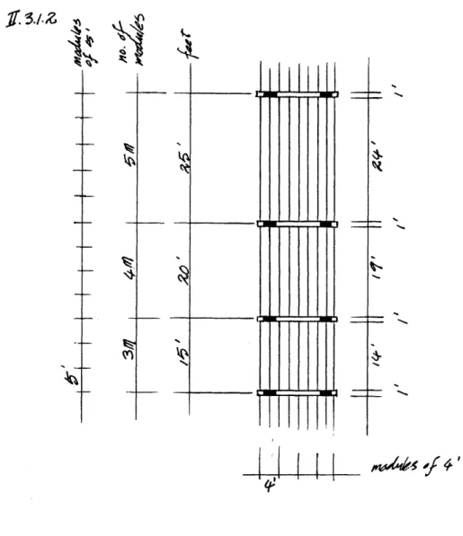
11.3.1.1.1 Floor spanned between portals The deck thickness and the deck length are
already determined by the different intervals between two portals. The lengths of intervals between two portals are 15', 20', and 25' .
Be-cause of the portal thickness between two decks, the real lengths of spanning by the floor deck are 14', 19' and 24'respectively. However, the spans will still be interpreted as 3 modules, 4 modules, or 5 modules in length at multiples of
5,.
The portals are designed to allow room on top so that mechanical systems can pass through. However, one of the function of the portals is to support the floor. Therefore, a, special support system is needed (fig 11.3.1.1.1). This special system is to be put into place after the portal is installed on site.
11.3.1.1.2 Floor spanned between beams
The floor decks are spanned between beams outside the row of portals. In order to keep the same interval between the end of two decks and to keep the increment of the beam length the same throughout the system, the width of the joint between the ends of the two decks must be equal to the exact width of the portal plus the
"L I
UL=
1.3//Z
I I I I II. PRIMARY SYSTEM
I I
I .
II.
PRIMARY SYSTEM11.3.1.2 Dimension of floor decks
Figure 11.3.1.2 shows the dimension of
the floor. ir a / 2
11.3 Detail Description of Elements
No
I
~5.
II. PRIMARY SYSTEM
11.3.2 Portal
The portals are precasted reinforced con-crete elements. They are double storey
struc-tures. Due to their extreme height, each por-tal is built with an extra horizonpor-tal element at the middle for the purpose of bracing. The arch form of the portals is also designed to serve the same purpose.
The functions of the portals are 1) to support directly the floor decks within the
row of portals lining up along the girder
di-rection, and 2) to support the girders placed along both edges of the portal. The
mechan-ical system is mainly carried along the row
of portals. The design of the portal has pro-vided room close to the ceiling for the me-chanical circulation. Oversized meme-chanical equipments can be circulated under the arch of the portal. Each portal has specially de-signed elements around mid-height which the supporting element for the secondary floors can be rested on.
11.3.2.1 Position of portals
There are two directions of placing the portals. One direction is to place the portals
11.3 Detail Description of the Elements
-- --
----
11.1.11j"111111il
11.3 Detail Description of the Elements
11.3.2.1.1 Placing portals along the girder direction
A range of intervals between the portals is desirable; however, it should be within the maximum
spanning capacity of the floor deck chosen. Although longer distances can be achieved by putting a beam in between the portals to support the floor decks, there are reasons not, to do that.
The first reason is because the beam is supported by the girders spanning between the portals, this means that the girder depth will have to increase because the longer the span is, the greater the load receives. Consistence in depth of the girders and provision of enough headroom for the secondary floor is preferable. The second reason is because of the beam being right under the ceiling. The original concept of having the mechanical systems circulate immediately under the ceiling will be complicated.
Although columns can be placed underneath the girders to shorten the span ,the beam is still
in the way. Nevertheless the column can be placed at the ends of each row of portals and therefore,
thematically, no beams should be span within the row of portals.
At this stage, the position-relation among all elements to the grid has already been established in section 11.2.2 . The intervals between the vertical elements or the lengths of the horizontal elements can be interpreted in terms of modules. The different intervals between two portals should be chosen from the multiples of a same number.
The lengths of 15', 20', and 25' in a modular system of 5' seems to be a pretty good range for the distances between two portals at the floor spanning direction which also is the same as the girder direction. Moreover, it is within the maximum spanning range of the 8" flexicore concrete decks which
is the most commonly used size of slab. Now, the intervals between portals can be interpreted as 3
modules, 4 modules, or 5 modules of 5' apart.
11.3.2.1.2 Placing portals along the beam direction
The different distances between two portals at the beam direction will be determined by the various beam lengths. This is the most desirable direction for the location of columns. Since all elements in this direction are positioned at multiples of 4', the intervals between portals in this
II. PRIMARY SYSTEM 11.3 Detail Description of the Elements
11.3.2.2 Dimension of portal
Figure 11.3.2.2 shows the dimension of the portal.
Y
3-2.1/
w
_4z
HWI-F--H
4-1±+tfHA411N]4H-1 F#
11.3 Detail Description of the Elements
11.3.3 Girder
The girders are precasted prestressed
re-inforced elements.
11.3.3.1 Position of girders
The girders are normally positioned be-tween either two portals or two columns. They are seldomly placed between a portal and a column unless this does not require an ex-tra beam to be placed in between; other-wise, the orignal purpose of providing room for the mechanical circulation system right underneath the ceiling will be defeated. It
is preferable that the girders are lining up
end to end for the purpose of transmitting the lateral force; otherwise, a special joint is needed.
The range of the girder lengths is ex-actly equal to the range of intervals between portals. It increases in modules of 5' starting from 15' up to 25'. Therefore, a girder 15' in length can be interpreted as 3 modules of 5'
in length. The interval between two girders in the beam direction will be determined by
the portal width or the beam lengths which
is interpreted in 4' modules. /
Lii
-V I I i I I I iI I
II
I a
II. PRIMARY SYSTEM
I I I I I
I I I
II. PRIMARY SYSTEM
11.3.3.2 Dimension of girders
Figure 11.3.3.2 shows the dimensions of the girder.
11.3 Detail Description of the Elements
* ~ 44 .9A7 ~
~-H-+-H--H-VH-HH-
6III III liii liii III III II II I I II #- /
I
44-. Owr,44 -ra44V
2 ( ,F I I I I I I I11.3 Detail Description of the Elements
11.3.4 Beam
The beams are also precasted prestressed concrete
elements.
11.3.4.1 Position of beams
The only position the beams can be placed is
di-rectly on top of the girders. The existance of portals along the plane of the direction of beams allows the beams to move along the girder direction freely. The ends of the beams are always line up with the centerline of the transverse section of the girder.
The tee-shape of the beam is designed to support the floor decks with a distance equal to the width of the portal plus the angles so as not to disturb the consis-tency of dimension of the floor decks.
The length of the beams increases in modules of 4' up to a maximum of 7 modules ( 28') which is a typical
span for the depth of a 2' deep beam. This implies that the interval between portals along this direction will also be increased at multiples of 4' depending on the length of the beam. It is important that the module of the length of the beams is a denominator of the module of the portals.
The intervals between two beams are equal to the length of the span plus the width of the joints, which are 15',20', and 25' at multiples of 5'.
/ __._ Q V fl
1f'
t-t 1'I.
r
II. PRIMAIRY-SYSTEM II
I
I ,
II. PRIMARY SYSTEM 11.3 Detail Description of the Elements
11.3.4.2 Dimension of beams
Figure 11.3.4.2 shows the dimensions of the beam.
444IHI
H44 iiili
I -q-z
Ad
11.3 Detail description of elements
11.3.5 Column
The column is the last to be design among all other structural elements in the primary
system. The process of designing columns is
highly influenced by the way the overall
sys-tem works since the position relationship of all other structural elements are already de-termined. It is important for the design of the columns to follow the development of the system instead of working against it. It is vi-tal to keep the design of the joints and the lengths of the elements consistent through-out the system. However, the vertical conti-nuity of the column should not be neglected or sacrified.
The columns basically can be divided into two categories. In the first category, the column is designed to have an option of placing on top of the portal. In the second category, the column is not designed to be placed on top of the portal.
ht~Kht~
hi
3;
II
IT - I i ,I
-4
II. PRIMARY SYSTEM 11.3 Detail Description of Elements
11.3.5.1 Column a - Column designed to be position on top of the portal
The size of the foot of the of the
col-umn should not exceed the size of the top
of the portal. In this case, the longer side of the section of the column is parallel to to the beam direction. The design satisfies the criterion that the column must be placed on top of the portal and at the same time pro-vide support for the girders and the beams without sacrifying the vertical continuity of the column itself.
I I
II. PRIMARY SYSTEM 11.3 Detail Description of Elements
11.3.5.2 Column b - Column designed
not to be positioned on top of the por-tal.
There is more freedom in designing the column in this case because it normally starts
from the ground. However, consideration shoulds be given not to disturb the dimen-sional consistency in length of the girders and the beams. There are two different
de-velopments in column b - column bI and
column b2. The design of column bi has its central axis lined up with the plane where the beams may be positioned. The design of column b2 avoids lining up with the plane where the beams may be positioned.
I I
II. II. PRIMARY SYSTEM
-11.3.5.2.1 Column b
This is an example of a column that is designed not to be placed on top of the portal and, at the same time, not to have its central axis lined up with the plane where the beams may be positioned.
Detail Description of Elements
II. PRIMARY SYSTEM 11.3 Detail Description of Elements 11.3.5.2.2 Column b2
This is an example of a column that is designed not to be placed on top of the
por-tal and, at the same time, not to be lined up with the plane where the beams may be
positioned.
=
EEYF1
II. PRIMARY SYSTEM
11.4 Relation in the System
11.4.1 Horizontal relation in the system There are two axis to the horizontal re-lation in the system. One axis follows the direction of the girder, and the other follows the direction of the beam. The two are per-pendicular to each other.
11.4 Relation in the System
- -
I ,
II. PRIMARY SYSTEM 11.4 Relation in the System
11.4.1.1 Horizontal relation of elements along The girder direction
sen are 15',20, and 25' based on a common
module of 5'. The sum of the smallest and .
the largest intervals is twice the length of q
the interval in between. Figure 11.4.1.1 gives
only the vertical elements as an example to illustrate the dimensional relations of the dif-ferent intervals.
I I
II. PRIMARY SYSTEM 11.4 Relation in the System
11.4.1.1.1 Position of portals along the girder direction
Portals usually line up in a row so that the girders are placed end to end to transmit the lateral forces in this direction.
11.4.1.1.1.1 A single row of protals
.---A single module of portals lining up strai-ght along the girder direction. Lateral forces along the girder direction is transmitted through the girders.
11.4.1.1.1.2 Connecting two overlapping
-rows of portals
Figure 11.4.1.1.1.2 shows rows of portals
shifting 1 module, 2 modules, and 3 mod-ules of 4'. Columns are used to make the transition. Doubling the number of columns
in each row with extra connection will help
----to form a better connection. This is also an appropriate place to put shear walls.
11.4 Relation in the System
11.4.1.1.2 Position of girders along the girder direction
Girders are normally lining up straight end to end except, at the intersection of shift-ing rows of portals (See section 11.4.1.1.1.2). The lengths of girders in the girder direc-tion is in a modular of 5' of no more than the maximum span of the floor deck which
is 25'.
11.4.1.1.3 Position of beams along the girder direction
The intervals between beams in the gir-der direction is also in modules of 5' of no
more than the maximum span of the floor
deck which is 25'. The position of beam can choose either to line up or not to line up with the portals.
11.4.1.1.3.1 Beams lining up with por-tals on both sides
Figure 11.4.1.1.3.1 shows the position of
all beams line up with portals on both sides. 11.4.1.1.3.2 Beams lining up with por-tal on one side
Figure 11.4.1.1.3.2 shows the position of
-on -" -
~-/ /#4
K
K-II. PRIMARY SYSTEM
I I
II. PRIMARY SYSTEM
11.4.1.1.4 Position of columns along the
girder direction
1-In the girder direction, thematically columns
are not positioned within a row of portals ex-cept at the end of the row or at the interlock-ing connection of a shiftinterlock-ing row of portals. However, rows of columns can be placed on their own alongside a row of portals . This
is a method employed to extend the distance
between two portals.
The columns can be positioned either in line with or not in line with the portals. 314-1.
11.4.1.1.4.1 Row of columns positioned
in line with portals
All three types of column, column type a, type b1 and b2, are in line with the portals. 11.4.1.1.4.2 Row of columns positioned not in line with portals
Some of the columns are not in line with the portals in all three types of columns.
n~E
11.4 Relation in the System
hA
I
~A1
4'
--- m--n LK
L..H
IA I ---o-tA9,1
II. PRIMARY SYSTEM
11.4.1.2 Horizontal relation of elements along the beam direction
In the beam direction, the interval
be-tween two portals is determined by the span length of the beam. Sometimes, column may be placed in between portals to increase the distance between two portals in this direc-tion. The module used for the beam is 4': therefore, the interval between two portals
as well as the length of the beams will be a
mutiple of the 4' module. They can be in-terpreted as, for example, one module apart, two modules apart, or seven modules apart.
1
tL-.LA--" U--AA--Un
F1
0
n
F]
F1
[7rrn"U
11.4 Relation in the System
n in
F-1
0
n
F1 F
n
F-1
F.].. ,
u-a-F-1
F]
II. PRIMARY SYSTEM
11.4.1.2.1 Position of portals along the
beam direction
Interval between portals in the beam
di-rection is normally determined by how many
beams of what length are in between, includ-ing columns . Positioning of portals in this direction has much more freedom than in the girder direction because the portals are not required to line up in a same plane with each other.
11.4.1.2.1.1. Rows of portals lining up
adjacent to each other
It is important to notice that in this
sit-uation, two rows of portals share the same row of girders; therefore, no portals can be lined up right next to each other.
11.4.1.2.1.2 Rows of portals a module
or more apart
A beam must be introduced between two portals if they are a module or more apart along the beam direction. If the interval is 4 modules apart , an additional row of portals can be put in between; however, the position
of the these portals in the middle should not
11.4 Relation in the System
JA4/.2. /
f9AL9/4L49
iM9
104
f999A
kAfW
-- --- -M--O
-- -
-
-
-7-I
I Wi
FT
1 11 11 1
'W;qMVW
I i n
II. PRIMARY SYSTEM
11.4.1.2.2 Position of girders along the beam direction
Girders can be placed on top of either side of the portal. or on top of either side of the column in column type a, or directly on
top of the center of column type b.
11.4.1.2.3 Position of beams along the
beam direction
Beams can be positioned on top of gird-ers between portals or between a portal and a column. Sometimes, they may even be placed directly on top of column in some types of column. The beam length varies from 1 module up to 7 modules of 4' (See
also figure 11.4.1.2.2) .
hE 4rF tE
i
.1
II. PRIMARY SYSTEM
11.4.1.2.4 Position of columns along the beam direction
There are two types of columns as men-tioned before in section 11.3.5 , column type a and column type b. The positions allowed in each type is different due to the difference in orientation of the wider side of the column in each type.
11.4.1.2.4.1 Columns placed on top of portal
Column type a, because its width basi-cally occupies almost the whole length of the module in the beam direction, has less choice of positions than column type b within the same interval between two portals. The
col-umn supports the girder at its side.
11.4.1.2.4.2 Columns placed not on top of portal
Column type b has one more choice of positions than column type a within the same interval between two portals in the beam
di-rection which is the central position. The column support the girder directly at the
center from underneath.
11.4 Relation in the System
F -1 '
-1
-=F-I
R
|101
g..14
11.4 Relation in the System
II. PRIMARY SYSTEM
11.4.2 Vertical Relation in the System The vertical relation in the system in-cludes elements like portals and columns.
11.4 Relation in the System
11.4.2.1 Vertical relation of portals
There are different types of portals ac-cording to height, and they have different re-lations with each other.
11.4.2.1.1 Types of Portal
The three types of portal a, b, and c are
11', 16-1/2', and 22' in height respectively.
Their widths are the same. They are equal to 4 modules of 4' and can be deployed in a grid of 4' modules in the beam direction.
11.4.2.1.2 Relation in Portals in height a
The relations of the vertical dimensions of the portal types are a = 2c and a + c =
2b. This provides a lot of different combina-tions among vertical stacks if portals can be achieved, resulting in a lot of different com-binations of floors.
-
II. PRIMARY SYSTEM 11.4 Relation in the System 11.4.2.1.3 Stacking of portals
The portals can be placed right on top of each other; however, they should not be supported by columns.
11.4.2.1.3.1 Portals stacked according to height.
The heigth of floors may be created from high to low starting from the ground.
11.4.2.1.3.2 Portals stacked irrespective
of height
Different floor heights can be created at the same level.
11.4.2.1.3.3 Stacking a portal across the 2
top of two portals ./
This is a interesting move and can be done occasionally under the condition that the two portals supporting the third portal are 2 modules apart, and at the same time the three portals are lined up in the same
plane along the beam direction.
On o
II.4 Relation in the Systemn
II. PRIMARY SYSTEM 11.4 Relation.in the System
11.4.2.2 Vertical relation of columns and portals As it is mentioned in section 11.3.5
ear-lier, there are two types of columns: the type
that can be placed on top of the portal - col-umn type a, and the type that cannot be
placed on top of the portal -column type b which again is subdivided into type b1, and
type b2. The vertical development of the two
II. PRIMARY SYSTEM 11.4 Relation in the System
11.4.2.2.1 Vertical relation of columns that placed on top of portal - Column type a
The design of this type of columns is
heavily restricted by the fact that it is lo-cated on the top of the portal. Every design consideration should respect the size of and the location of the support from the portal below.
11.4 Relation in the System
11.4.2.2.1.1 Vertical position of column type a
Under this type, the placement of a
col-umn is greatly influenced by the position of
the portal it is resting on, and vice versa.
11.4.2.2.1.1.1 Location of a single
col-umn above a portal
A specific location of a column is
re-quired by a location of a portal underneath to support it, unless the column is started from the ground.
11.4.2.2.1.1.2 Location of two columns above a portal
Each portal has two specific locations for the placement of a column.
n~r~
rnz)
CE)ZI
4~q~AF]
N~ d0 -4 ~~~~~~4' lwil NJ f f'Pd O1f 4f'
n-4
I I
II. PRIMARY SYSTEM
11.4.2.2.1.1.3 Location of coluinns above three adjacent rows of portals
Under this situation , the columns will be 3 modules away from the central row of portals if only the middle row of portals goes up. Moreover, if another row of portals at the edge is equal to or less than 3 modules away from the outside row of the three cen-tral rows of portals, the floor above requires no column in between the portals.
1. 2.. I.;g.4
11.4 Relation in the System
I I I
i i
II. PRIMARY SYSTEM
11.4.2.2.1.1.4 Location of columns in
sit-uation of two portals supporting a third portal across.
Under this situation, the columns will be 2 modules away from the central row of portals. If the maximum interval between the row of portals at the edge and the out-side row of portals in the middle at the bot-tom is equal to or less than 4 modules, the floor above requires no column in between
the portals.
II.4 Relation in the System
9H
1
MfA
7
5AI I
II. PRIMARY SYSTEM
11.4.2.2.1.2 Decreasing section of the column type a
The relation of the column may be
re-duced appropriately in the vertical develop-ment according to the load it must carry. A higher floors the section of the column may decrease and/or a different material may be used.
I I
II.
PRIMARY SYSTEM11.4
Relation in the System11.4.2.2.2 Vertical relation of a column
not on top of the portal - column type b 0.42.11 As is mentioned in section II 3.5.2 , there
are two different types of development in col-umn type b : colcol-umn type bi and type b2. There is relatively more freedom in the sign of these types of column than in the de-sign of column type a, because there will be no dimensional restriction imposed from the portal.
IF11
1-_T I WA W 1MIO 4
11.4 Relation in the System
11.4.2.2.2.1 Vertical position of column type b
Column type b has no positional restric- 942Az .2
tion relative to the location of the portals. A
Nevertheless, the position of the column still has to respect the location of the girder.
One interesting possibility is, if the width of a type b1 column is long enough, the
umn may be able to support a type b2 col-umn on top of it (see figure 11.4.2.2.2.2.3)
11.4.2.2.2.2 Decreasing in section of the column type b
The section of column may be reduced when the loads decrease. This may eventu-ally lead to significant change of the form of the column. It is again very important not to change the position, relative to the grid,
of the girder or the beam it receives. Figure
11.4.2.2.2.2.1 shows the decrease in section II.__ PRIMARY
SYSTEM-III. SECONDARY SYSTEM
There are two types of secondary tem in this thesis, the secondary floor sys-tem and the partition syssys-tem. Neither the installation nor the removal of any part of such systems should involve any changes in the primary system.
111.1 Secondary Floor System
III. SECONDARY SYSTEM
111.1 Secondary floor system
The secondary floor system includes hor-izontal elements and vertical elements. Since the idea of a secondary system is that it can be erected or demounted without
affect-ing the primary system, it should be build
of light weight material, and the method of jointing the elements should not be perma-nent.
The choice of materials for a secondary system can vary a good deal according to the preferance of designers or users. Never-theless, there is a principle for choosing the material for the girders and the beams (See section III.1.1.1).
n
rTFII
F-I
F-I
F-I
III. SECONDARY SYSTEM
111.1.1 Types of element in the secondary floor system
There are two types of elements, the ver-tical elements and the horizontal elements.
111.1.1.1 Horizontal elements of the sec-ondary floor system
The horizontal elements include girders, beams, and floor decks. The spans of sec-ondary floors between portals are relatively long; this is beacuse the girders spanning between portals should be capable of span-ning that distance without the support of columns; otherwise, there will be too many secondary columns within the interval be-tween portals. Nioreover, the beam must cantilever from the row of portals to provide an extra 4' space intended for circulation on the secondary level, so the material used for the beams should be allowed for relatively long spans. The material chosen for the gird-ers and the beams in this thesis is Gluelam. The material for the floor should not be per-manent. It should be relatively easy to as-semble. Wood seems to be an appropriate material for the secondary floors.
f..//
lJJiJik
I
ilIHiTE I U___IL_ U 1 1 1n
III.1 Secondary Floor System
om I N
j
I
111.1 Secondary Floor System
111.1.1.2 Vertical elements of the sec-ondary floor system
The vertical elements include supports
for the girders from the portal and columns. The device connecting the girder to the
por-tal should be designed according to the way the girder is supported by the portal. In this
case, the girder is rested on top of a short
horizontal element placed in a built in slot
at an appropriate height of the portal. The columns can be of any material as long as they are demountable.
-jf. /.12 SECONDARY SYSTEM
I I
III. SECONDARY SYSTEM
111.1.2 Relation of the elements of the
secondary system to the grid
~f. /
AOO-111.1 Secondary Floor System
I0'
III. SECONDARY SYSTEM 111.1 Secondary Floor System 111.1.3 Direction of the secondary floor system
There are two directons of the secondary
floor. One of them is in the girder direction, and the other is in the beam direction.
111.1.3.1 Development of the secondary
floor along the girder direction
In the direction of the girder, the beam
in the secondary system can cantilever its
floor 4' out of the row of portals. This 4'
space can be used as a continuous circula-
-tion for the secondary floor; therefore,
peo-ple can have two options of circulation on .
the secondary floors. They can either circu-late outside the row of portals or circucircu-late through the row of portals.
111.1 Secondary Floor System
111.1.3.2 Development of the secondary floor along the beam direction
In the beam direction, there can be no
continuous circulation outside the portals for the secondary floor. It has to be done within the space between two portals. The floor itself can only occasionally cantilever 4' out of the end of the portal.
I I
III. SECONDARY SYSTEM 111.2 Secondary Partition System
111.2 Secondary partition system
111.2.1 Types of secondary partition sys-tem
There are two types of partition system. The first type, partition type a, is to be put on top of the primary floor as well as the secondary floors, and the second type,
parti-tion type b, is to be put only on the primary
floors.
111.2.1.1 Secondary partition type a
This type of partitions normally instal-led after the secondary system is in place. The partitions should be made out of light weight, material, for example, a two-by-four stud wall system. They can be used for a relatively short period of time. They can be manipulated more frequently to create dif-ferent configurations for difdif-ferent purposes in the course of the lifetime of the building.
111.2.1.2 Secondary partition type b
This type of partitions can be made out of relatively heavy material, concrete blocks for example. They are used for relatively permanent separation. Nevertheless, the
de-III. SECONDARY SYSTEM
111.2.2 Relation of the partitions to the grid
g.,z-z.
kCoo
(J III 0
111.2 Secondary Partition System
111.2.3 Direction of the secondary par-tition system
There are also two directions for each
type of partition, namely the girder direction and the beam direction. Both directions of partition can exist simutaneously in any di-rection of development of both the primary and the secondary floors.
111.2 Secondary Partition System
111.2.3.1 Secondary partition on the floor development in the girder direction
.1r ./
111.2.3.1.1 Secondary partition type a
on the secondary floor in the girder
di-rection
111.2.3.1.1.1 Before further subdivsion
111.2.3.1.1.2 After further subdivsion
At.j/ ,
111.2 Secondary Partition System
111.2.3.1.2 Secondary partition type a
on the primary floor in the girder
di-rection
. . 1
111.2.3.1.2.1 Before further subdivision 111.2.3.1.2.2 After further subdivision
5I!2. .2.z
111.2 Secondary Partition System
111.2.3.1.3 Secondary partition type b
on the floor development in the girder
direction
i .f./fi
111.2 Secondary Partition System
111.2.3.2 Secondary partition of the floor
development in the beam direction
111.2.3.2.1 Secondary partition type a
on the secondary floor in the beam
di-rection
111.2.3.2.1.1 Before further subdivision III. SECONDARY SYSTEM
111.2 Secondary Partition System
111.2.3.2.1.2 After further subdivision SECONDARY SYSTEM
111.2 Secondary Partition System
111.2.3.2.2 Secondary partition type a on the primary floor in the beam di-rection
111.2.3.2.2.1 Before further subdivsion
g.12.2.|.
SECONDARY SYSTEM
111.2.3.2.2.2 After further subdivision
N.
A~2. I -I a a a - - - ~ ~ I -- -- ----.. -a a a a a a111.2 Secondary Partition System qFC."NDARY SYSTEM
111.2 Secondary Partition System 111.2.3.2.3 Secondary partition type b
on the floor developnent in the beam
direction
IV. FACADE
In this thesis, we concentrate on the
de-sign of the primary system. The dede-sign of the facade is left to the-preferrance of indi-vidual designer. However, it is important for the thesis to include explanation of how fa-cade is related to the system.
IV. FACADE _
IV.1 Relation of Facade to the System
The facade will be supported by the girder
in the girder direction and by the beam in the
beam direction. Followings are some exam-ples demonstrating how the facede is related to the system in different situations.
IV.1.1 Brick Veneer Wall Figure IV.1.1.1
shows that the wall is supported by the girder
in the girder direction. Figure IV.1.1.2 shows
that the wall is supported by the beam in the beam direction.
IV.1.2 Metal Curtain Wall Figure IV.1.2.1
shows that the wall is supported by the girder
in the girder direction. Figure IV.1.2.2 shows
that the wall is supported by the beam in the beam direction.
IV.1 Relation of Facade to the System
1- .
Facade to the System
IV.1.3 Masonry Wall
Figure IV.1.3.1 shows the relation of the
wall to the system in the girder direction. Figure IV.1.3.2 shows the relation of the wall to the system in the beam direction.
IV.2 Portal along the edge
Girders supporting the facade can be supported by specially designed portals po-sitioned along the edge .These portals allow an additional 6' projection from the typical portals.
'I-,
ff-l-I
7-
44 I-1
IV. FACADE_ IV.1 Relation of
IV.3 Profile of the Edge
There are four ways to modify the
pro-file of the edge : indentation, shifting of
por-tals, introducing columns, and modifying the
--designed of the portals. - ..
IV.3.1 Profile of the edge along the girder
direction
The profile of the edge in the girder di-rection is relatively flat because the portals are usually lining up straight in this direc-tion. However, the profile of the edge can be modified by indentation (figure IV.3.1.1).
shifting of portals (figure IV.3.1.2), introduc- ---
-ing columns (figure IV.3.1.3) and modify-ing
.--the designed of .--the portals (figure IV.3.1.4).
IV.3 Profile of the Edge
IV. FACADE
IV.3.2 Profile of the edge along the beam direction
The profile of the edge in the beam di-rection can be more undulating than in the girder direction because the portal has more freedom to shift in this direction. The
pro-file of the edge along this direction can also
be modified by indentation (figure IV.3.2.1), shifting of portals (figure IV.3.2.2 ), intro-ducing columns (figure IV.3.2.3) and modify-ing the designed of the portals (figure IV.3.2.4).
H-zz-ow
jf.s
I~1
~42
~z~zHzzH
l~L
4HfLbIIz~~~iz
I
'111
V. PRINCIPLES OF HORIZONTAL DEPLOYMENT - BUILDING SCALE
V.1 Relation of Number of Rows of Portals to Their Intervals
Different number of rows of portals sug-gest different length of interval between them. It also suggests the location of the circula-tion. The longer intervals seems to be more appropriate to be located close to the edge, and the shorter intervals close to the middle. The circulation will mostly fall into the cen-tral rows of portals so that the work spaces have proximity to the natural sunlight.
V. PRINCIPLES OF HORIZONTAL DEPLOYMENT - BUILDING SCALE
V.1.1 Two rows of portals
With only two rows of portals, the in-terval between the the rows should be maxi-mized as possible because of the proximity to
the natural sunlight on both sides. Interval - - - -
-of 6 or 7 modules is appropriate. Sometimes
a row of columns can be introduced to
in-crease the distance.
---V.1.2 Three rows of portals
In the case of three rows of portals, the - - -
-interval range may be from 4 to 6 modules.
The circulation is most likely to be placed
-inside the central row of portals.
V. PRINCIPLES OF HORIZONTAL DEPLOYMENT - BUILDING SCALE
V.1.3 Four rows of portals
In the situation of four rows of portals, the interval between the inner two rows should be the shortest, for example, 2 or 4 modules
in length. The appropriate length of other - .
-intervals should be 4 to 5 modules. The cir-culation can be located in either row of
por-tals which is close to the middle.
V.1.4 Five rows of portals - - - -
-Five rows of portals is the maximum number of rows that can go without the
in-troduction of courtyard either in the mibble - . . - -
-or at the side. The intervals which are close
to the middle should be short compared to - - -
-the intervals close to -the edges. The
circula-tion is most appropriate to be put inside the
middle row of portals.
V. PRINCIPLES OF HORIZONTAL DEPLOYMENT - BUILDING SCALE
V.2 Relation of distance between portals to circulation
AI
This series of exploration are to inves-tigate how the variation of distance between rows of portals influences the configuration of the circulation. The variation of distance between rows of portals will be done with a fixed number of rows and within a fixed
over-all width. We will use five rows of portals
from the last section as an example. The ex-ploration will start form the case with smaller distance up to the case with bigger distance between the middle rows-of portals.
0 0
V. PRINCIPLES OF HORIZONTAL DEPLOYMENT - BUILDING SCALE
V.2.1 Five rows of portals - Case 1
With five rows of portals, the middle
row of portals seems to be the most suitable
location for the public circulation because it
is the place where it is too deep for the
sun-light to get to. The zone of 2 module-wide space which is next to the middle row of por-tals is good for spaces used as service-related activities like storage rooms or rest rooms, for example, it can be the location of verti-cal circulation like stair-ways and elevators (figure a). The zone of space is also wide enough for the location of a secondary
pub-lic circulation to the main circulation (figure b).
kg
r-
-4-~~I
j~j' i M W - L~ L~ 4%r~
r~
--- --P
I
V. PRINCIPLES OF HORIZONTAL DEPLOYMENT - BUILDING SCALE
V.2.2 -d
V.2.2 Five rows of portals - Case 2 In this case, both intervals next to the
central row of portals are equal to 4 mod-ules. The central row of portals again can be used for the public circulation, and the zone of space in between two rows of portals on both side of the circulation can be used
as the service spaces (figure a). With inter-val of 4 modules on both side of the cental row there will be too much space for just to
accomodate the service activities, and plus the size of the space the zone of space is also good for the location of a small community meeting space, for example, a small lecture room or a conference room (figure ). The circulation in that area will have to be lo-cated inside the row of portals next to the central row on both side.
-1
--- ---
'
-7
-
:
4 t4LIIJIL
/44,
V'
-
1
--V. PRINCIPLES OF HORIZONTAL DEPLOYMENT - BUILDIN
Y2.3 -A .
V.2.3 Five rows of portals - Case 3 In this case, the intervals next to the
central row of portals are 6 modules in length. The zone of space next to the central row of portals is best for the location of a large com-munity meeting space, for example, a large lecture room or an auditorium. The three figures, figure a, b, and c, show three differ-ent sizes of a community space in the same arrangement of rows of portals, and their re-lations to different configurations of circula-tion created from the arrangements.
~
~T
I
I Ik
/
-/-G SCALE kv L ~L -~~-J~ r --~j1
7'
HIT--
=0_ - m
-V. PRINCIPLES OF HORIZONTAL DEPLOYMENT - BUILDING SCALE
V.2.4 Five rows of portals - Other cases -
-There are also other cases in between
those described earlier. They can be inter- - - -
-preted the same way as the cases we have -
-studied earlier.
Id
4
{
V. PRINCIPLES OF HORIZONTAL DEPLOYMENT - BUILDING SCALE
V.2.6 Five rows of portals - Substitution by row of columns
Sometimes, a row of portals can be sub-stituted by a row of columns.
~Zz~
V.2.6 Five rows of portals - Change of overall dimension
Besides the length of the intervals can be changed, the overall dimension can also . be changed.
(4YI
it--JL A..n
110 1 4M
V. PRINCIPLES OF HORIZONTAL DEPLOYMENT - BUILDING SCALE
V.2.7 Five rows of portals - In the beam direction
The same method of interpretation can be applied on the rows of portals running along the beam direction.
VI. PRINCIPLES OF VERTICAL DEPLOYMENT - BUILDING SCALE
VI. Principles of Vertical Deployment
The intention of this series of diagrams of the deployment of the primary system is , firstly, to show the hierarchy of the order of structural elements in the vertical direction. Secondly, it is to illustrate the principle of the "thinning" of structure which the num-ber of elements decreases upward. There will be lesser quantity of elements at the top than at the bottom. Thirdly, it is to give exam-ples of decreasing in material of the elements. This six storey building is only an example.
Building Scale
0 ElrI n
00 Co
VI. PRINCIPLES OF VERTICAL DEPLOYMENT - BUILDING SCALE
1st Floor
I I I I I I
The bottom floor has the greatest quan-tity of structural elements since every piece of element above has to be supported from below, and the quantity of element will only
decrease upward. Ion
...
r
! + 1 *414M 1MI 4H -.1 ld 14d 1144 1 A 1 __ -I ... ... ... 11111 C)Ck. C)
VI. PRINCIPLES OF VERTICAL DEPLOYMENT - BUILDING SCALE
2nd Floor
The quantity of structural elements starts decreasing. Some portals have been replaced
by columns.
ono
1 00 0 03 M2 M2 MC 1 *41 *11 *11101 4M 1401011 Itl 1401-VI. PRINCIPLES OF VERTICAL DEPLOYMENT - BUILDING SCALE
3rd floor
There are more portals replaced by columns There is also a shifting of one row of por-tals from directly above another row to span across two rows of portals. There is only four rows of portals on this floor compared to the five rows of portals on the floor below. The configuration of both structure and space are very different from the floors below.
i=ir~n
A4A i 4d 18 4 1 3M 1 4m 14 A1 4M i 4_ Q O Q Q 1 0 D O 0VI. PRINCIPLES OF VERTICAL DEPLOYMENT - BUILDING SCALE
4th floor
A whole row of columns disappears. One of the span between two rows of portals
be-comes bigger. The density of structural ele-ments is lower than the floors below.
_M iLld A M1tt4M 1