Cognitive Techniques in Smart System
Technologies
by
Anteneh Shiferaw
Submitted to the Department of Civil and Environmental
Engineering
in partial fulfillment of the requirements for the degree of
Master of Science in Civil and Environmental Engineering
at the
MASSACHUSETTS INSTITUTE OF TECHNOLOGY
February 1997
@
Massachusetts Institute of Technology 1997. All rights reserved.
I,
Author.
ea4tment of§vil an
vironmental
Engineering
January 17, 1997
0
Certified by...
..
Jerome J. Connor
Professor
Thesis Supervisor
A ccepted by ...
.
...
...
Joseph M. Sussman
Chairman, Departmental Committee on Graduate Students
JAN 2 9 1997
IIEBRAR:IES
Cognitive Techniques in Smart System Technologies
by
Anteneh Shiferaw
Submitted to the Department of Civil and Environmental Engineering on January 17, 1997, in partial fulfillment of the
requirements for the degree of
Master of Science in Civil and Environmental Engineering
Abstract
Remarkable advances in microelectronics and data processing technology have made possible the realization of a new class of systems - smart systems. As control systems
become increasingly complicated and generate increasingly complex control informa-tion, smart systems provide a means of recognizing multidimensional information and processing this information to provide a useful response. The ability to observe, de-cide, and act are fundamental to the smart system. This thesis looks at the current state of smart system technologies with a viewpoint on some of the issues that are important in their implementation. A newer concept of intelligent control, involving knowledge based systems, fuzzy control and artificial neural networks, is also looked at.
Also, a state-space formulation is used in extending the idea of hierarchical control and finite element concepts to the analysis of a shear beam. This analysis further discretizes an already discrete system in order to reduce the computational effort re-quired in the simulation. The result is a hybrid approach that synthesizes constraint conditions and the eigenvalue problem.
Thesis Supervisor: Jerome J. Connor Title: Professor
Acknowledgments
The author wishes to express his deepest gratitude to his thesis advisor, Professor Jerome J. Connor, for his guidance, invaluable suggestions, constant encouragement, and precious advice during the course of this study.
Thanks are also due to the fellow graduate students for their helpful suggestions and discussions.
Finally, the author wishes to thank his family for their support and encouragement, without which this work would not have been possible.
1 Introduction
1.1 Definition of a Smart System . . . . 1.2 Historical Perspective ...
1.3 Intelligent Behavior . ... ... 1.4 Components of a Smart System . . . ...
1.4.1 Sensors ... . ... 1.4.2 Cognition . ... 1.4.3 Actuators . ...
1.5 Practical Applications of Smart Technology . .
1.5.1 Placement of Piezoelectric Actuators in A 1.5.2 Intelligent Buildings . ...
1.5.3 Fuel Injection Control in Intelligent Auto 1.6 Scope of Thesis . ... 10 ... . . . . . 10 ... . . . . . 10 ... . . . . . 1 1 ... . . . . . 1 1 . . . . . . 12 \daptive Trusse mobiles. . . . . 13 . . . . 13 . . . . 14 s... 14 . . . . 14 . . . . 15
2 Intelligent Sensor Technology 2.1 Sensors: A Definition . ... 2.2 Making Sensors Intelligent . . . .. 2.3 Types and Applications of Sensors . . . . 2.3.1 Sensors Classified by Type of Input . 2.3.2 Sensors Classified by Type of Output 2.3.3 Sensors Classified by Accuracy . . . 2.4 Sensor Signal Conversion . . . .. 2.4.1 Signals and Sensors . ... 17 ... . . . . 17 ... . . . . . 18 . . . . 18 . . . . 19 . . . . 19 ... . 19 .. . . . . . 20 .. . . . 20
Contents
2.4.3 Analog Type . . ... .22.
2.4.4 Digital Type ... . . . . . 23
2.5 Nature of Smart Sensors .. ... ... ... ... 23
2.6 Sensing Element Technologies ... . . . 25
2.6.1 Characteristics ... . ... . 25
2.6.2 Piezoresistive Sensors . . . ... . . . 26
2.6.3 Capacitive Sensors . ... . . . 26
2.6.4 Piezoelectric Sensors . ... ... .. 27
2.7 Characteristics of Smart Sensor Technology . .... . . . . . . 27
2.7.1 Primary Sensing Element ... . . . 27
2.7.2 Amplification ... . . . . . . . . . 29
2.7.3 Digital-to-Analog Conversion ... .. 30
2.7.4 Signal Conditioning ... . . . . . . . . . .... . 30
2.7.5 Information Processing . ... . . . . 31
2.8 Integration ... ... . ... ... . 32
3 Control in the Cognitive Unit 33 3.1 Conventional versus Intelligent Control . ... 33
3.2 Conventional Control ... ... 34
3.3 Performance Criterion of Control Systems . ... . 35
3.3.1 Performance Requirements . ... . 36
3.3.2 Control System Specification ... ... . . . 36
3.4 Performance Indices ... ... ... . 38
3.5 Control Types ... ... . 38
3.5.1 Proportional Control . ... . . . . . 39
3.5.2 Derivative Control ... . . . . . . . . 40
3.5.3 Integral Control ... ... . 41
3.6 Feedback and the Effects of Feedback on Control . . . . 41 3.6.1 Effect of Feedback on Overall Gain
2.4.2 Signal-to-Noise Ratio
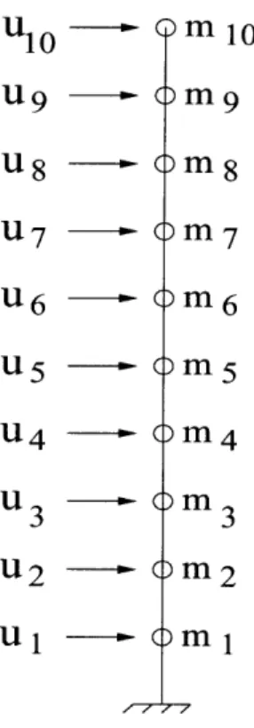
4 Control of a Shear Beam Using Principles
4.1 State-space Formulation . . . ... 4.1.1 Constraint Equations . . . . 4.1.2 Change of Coordinates . . . . 4.2 Damping Matrix ...
4.3 The Control Optimization Problem . . . .
4.4 Sim ulation ... ...
of Hie
4.5 Resimulation With All Nodes Acting Independentl 4.6 Results ...
4.6.1 Simulation With the Constraint Conditions
rarchical Control 57 .. . . . 57 .. . . . 58 .. . . . 59 .. . . . 60 .. . . . 60 . . . . . .. . 61 S. . . . . ... .. 63 . . . . . . 64 . . . . . 64
4.6.2 Simulation With All Nodes Acting Independently 3.6.2 Effect of Feedback on Stability . . . .. 3.6.3 Effect of Feedback on Sensitivity . . . . 3.6.4 Effect of Feedback on Noise . ... 3.7 Feedback Control Systems ... 3.7.1 Linear versus Nonlinear Control Systems . . . 3.7.2 Time-Varying versus Time-Invariant Systems. 3.7.3 Continuous-Data Control Systems . . . . 3.7.4 Sampled-Data and Digital Control Systems .. 3.8 Large-Scale Systems Control ... 3.8.1 Models for Large-Scale Systems . . . .. 3.8.2 Hierarchical Control of Large-Scale Systems 3.9 Intelligent Control . . . . . . .. 3.10 Ideas in Intelligent Control ... 3.11 Knowledge Based Systems ... 3.12 Fuzzy Logic ... ... 3.12.1 Fuzzy Logic Control ... 3.12.2 Aspects of Fuzzy Control . ... 3.13 Neural Networks for Modeling and Control . . . . .. . . . . 42 .. . . . 42 .. . . . 43 .. . . . 43 . . . . . 43 . . . . . 44 .. . . . . 44 . . . . . 44 .. . . . 45 .. . . . 45 . . . . . 46 .. . . . 48 .. . . . 48 .. . . . 49 ... . 51 .. . . . 51 .. . . . 53 . . . . . . 55
5 Actuation Techniques
5.1 Actuating Materials
5.1.1 Shape Memory Alloys ... 5.1.2 Electrorheological Fluid ...
5.1.3 Piezoelectric or Elastroelastic Materials . . . . 5.2 Modes of Adaptability . .... ...
5.2.1 Variation in Material Properties . . . ... 5.2.2 Change in Stored Strain Energy . . . .. 5.2.3 Application of Forces . . . ... 5.2.4 Transforming Energy from One Mode to Another 5.3 Stability in Shape Memory Actuators . ...
5.3.1 Partial Actuation . . ...
5.3.2 Long-term Stability of the Actuation Strain . . .
5.4 Piezoelectric Actuators .. ... 5.5 Active Structural Control . ...
6 Summary and Conclusions
6.1 Discussion ... 6.2 Future Developments ... 72 .. . . . 72 .. . . . 72 .. . . . 73 .. . . . 74 .. . . . 75 .. . . . 75 .. . . . 75 .. . . . 75 . . . . . . 76 .. . . . 76 .. . . . 76 . . . . . . 78 .. . . . 78 .. . . . 80 4.7 Conclusions ...
1-1 Pattern of Activity for a Smart System.. 2-1 General Transducer Model . ...
2-2 Essential Elements of a Smart System. . ... ... 3-1 Block Diagrams of Open- and Closed-loop Systems . . . . . . .
3-2 Proportional Control . ...
3-3 Control System with Derivative and Proportional Control . . . 3-4 Two-level Hierarchical System . ...
3-5 Methods in Intelligent Control .. ... . ... 3-6 Fuzzy Controller in Theory ... . . . . . . . .... 4-1 Shear Beam . . . . . . .
4-2 Mode Shapes of the Master Variables . . . . . . . .. 4-3 Displacements of the Model in the Reduced Coordinate System 4-4 Displacements of the Model in the Original Coordinate System 4-5 Displacements of the Master Variables . ... ... 4-6 Mode Shapes When All Nodes Act Independently . . . . 4-7 Displacements of the Independent Nodes . . . . . . . .. 5-1 General Deflection-Temperature Relationship for SMAs ...
5-2 A Generic Electromechanical Representation of an Active System with Actuator ...
6-1 Components of Adaptive Intelligence . ...
. . . . . 12 24 28 . . . 34 . . . 39 . . . 40 . . . 46 . . . 49 . . . 52 . . . 62 . . . 65 . . . 66 . . . 67 . . . 68 . . . 69 . . . 70
List of Figures
List of Tables
Chapter 1
Introduction
1.1
Definition of a Smart System
In recent years, "smart (intelligent) systems" has become an emerging new research area that is multi-disciplinary in nature, requiring technical expertise from mechanical engineering, electrical engineering, computer science, structural engineering, biolog-ical sciences, etc. The term smart system refers to a system that has sensors and actuators whose actions are coordinated through a control system giving the system the ability to respond spontaneously to changes in its environment to compensate for undesirable effects. A smart system is able to produce a useful or optimal response to an external stimulus by changing its material properties, geometry, mechanical or electromagnetic response.
1.2
Historical Perspective
Soon after the Second World War, scientists began to look for methods to make electronic devices solve problems in ways similar to human beings. Such devices were envisioned to have an "artificial intelligence". Because it depended on the use of the digital computer, the field of artificial intelligence could only arise in the modern era. At first the decision algorithms mimicked the internal architecture of the computers
and used linear sequential data processing. These algorithms were written in machine language and required processing of large amounts of numerical data. In time, higher languages were developed and new neurological and parallel processing computer (and algorithm) architectures were created. The result was new computer systems that used recursive non-linear techniques to respond to changes in input. Throughout, the fundamental paradigm that has driven advancements in this field has been the desire to create "biologically-inspired" systems.
1.3
Intelligent Behavior
There are three fundamental concepts that describe intelligent behavior: observation, decision and action. A smart system must have purpose and the ability to act. External stimuli produce some change in measured parameters that the system should be able to monitor. This multi-dimensional information is processed to produce a clearer understanding of the disturbing phenomena. Using the processed information, a control system decides on the optimal response required to return the system to its desired condition; action is then taken, in real time. All the while, the control system is receiving more information regarding the effects of its response and it may have to alter its response accordingly. This is the feedback/feedforward process that is inherent to truly smart behavior. A generic diagram showing this pattern of activity is shown in Figure 1-1.
1.4
Components of a Smart System
At the highest level, the sophistication of the overall smart system will in general require components that give the system the ability to detect and evaluate the data, to decide on a course of action and to carry out the action (through a knowledge of appropriate control laws). At lower levels in the hierarchy, similar, though less complicated, sub-systems can also exist.
parameter field
Figure 1-1: Pattern of Activity for a Smart System.
The three essential components of a smart system are briefly treated in the following subsections.
1.4.1
Sensors
A sensor is a measuring device. It is used for observing and measuring physical phenomena. Increasing complexity in systems has led to the generation of increas-ingly complex control information, usually, multi-dimensional in nature. As a result, sensors are an indispensible extension of our human senses, converting non-visual in-formation into a visual form that is more easily interpreted. Sensors are, therefore, a basis for information representation. A newer, more sophisticated, class of sensors
- the intelligent sensor - is emerging. Using combinations of different types of sen-sors (or sensor fusion) and a signal processing unit such as a computer, the sensing and data processing (or information processing) aspects involved in multi-dimensional measurement have been greatly enhanced by the advancements in micro-electronics. The essential characteristics of an intelligent sensor are:
* sensor fusion and data processing; * data processing by computer;
* performance of an intelligent operation by machinery.
Sensors are classified by the type of input and subject of measurement, type of output, accuracy and safety aspects.
1.4.2
Cognition
This second component is essentially the "brain" of the system. Based on input from the sensors and regular feedback, the cognitive component makes an intelligent de-cision on the optimal course of action to return a system to its desired condition. This area of artificial intelligence made dramatic progress only with the advent of the digital computer.
Fundamentally, the cognitive unit consists of numerical control and optimization al-gorithms. Three types of algorithms are:
* Control algorithms are currently the most feasible.
* Knowledge-based (or rule-based) algorithms consist of a set of conditional state-ments from which a course of action is chosen.
* Neural networks, which imitate more closely the functioning of the human brain, consist of nodes and their connections.
1.4.3
Actuators
Actuators are the physical component of the system. In response to an external stim-ulus, the actuators modify the system parameters according to the decided course of action. Natural systems seem to operate in a mode to reduce energy while contin-uously performing adaptive functions. Ideally, investigating the way nature carries out adaptive functions allows us to create actuation techniques that imitate those of nature. In general, the modes of adaptability can be classified as follows:
* Variations in material properties: This is critical in the field of smart materials where shape memory alloys (SMAs) have a significant impact.
* Changes in the stored energy of a system.
* Applications of forces, moments and torques. * Shifting from one energy mode to another.
The synergism of the above components, and accompanying developments in real-time information processing are making the concept of the smart system very attrac-tive.
1.5
Practical Applications of Smart Technology
1.5.1
Placement of Piezoelectric Actuators in Adaptive Trusses
An important application area of smart structures technology is the large truss, par-ticularly in a zero-g environment where there is no damping from gravitational forces. Vibration and stability problems, in particular, are putting performance restrictions in the field of lightweight space structure technology. The ARES (Actively React-ing Elastic Structures) project hopes to overcome these difficulties by usReact-ing a new class of smart systems characterized by the use of embedded sensors and actuators as well as digital real-time filters as adaptive controllers. Further research is concentrat-ing on the design of systems with integrated actuators out of shape memory alloys, magnetostrictive materials and piezoelectric polymers.
1.5.2
Intelligent Buildings
Intelligent buildings are making a significant impact on modern architectural prac-tices, particularly in the design of high-rise buildings. Their purpose is to benefit residents and building managers by optimizing environmental and safety aspects in an economical way. To achieve this, computers along with distribution control tech-niques are used to optimize the performance of different pieces of equipment such as air conditioning, electric devices, and fire-prevention and safety devices. The functions
can be divided into three parts: those supporting office automation; those allowing sophisticated data communication; and those required in building automation. The first two functions are concerned with improving the productivity in the office envi-ronment so as to improve the office output. The third one uses computer systems in the integration and the control of the various facilities (such as fire-prevention, electrical equipment and air conditioning).
1.5.3
Fuel Injection Control in Intelligent Automobiles
Smart system technology comprising sensors, microcomputers and actuators is in-creasingly being used in automobile systems to enhance comfort and performance. In fuel systems, fuel injection control is used to measure the amount of air entering the engine and to provide a corresponding amount of fuel. One method by which this occurs is through the use of temperature and pressure sensors which are used to mea-sure the air intake using Boyle's or Charles' law. Once the mass of air is determined, then based on the vehicle's running condition, an optimum mixture of air and fuel is determined. An injector injects the right amount of fuel in the from of a spray. The air-fuel ratio is set based on the molecular weight ratio where atmospheric oxygen and petrol burn without either being in excess. This is known as the stoichiometric air-fuel ratio.
1.6
Scope of Thesis
This thesis introduces the current status of smart system technology with the aid of some useful practical examples. It explains how these systems are organized and how they function. Chapter 1 introduced the concept of a smart system; Chapters 2 and 3 look at sensors and the cognitive unit (this chapter also looks at some of the developments in intelligent control). Chapter 4 applies the idea of hierarchical control to a shear beam model, and the results of a simulation in MATLAB are presented. Chapter 5 looks at the actuation techniques. Finally, the conclusions are presented
Chapter 2
Intelligent Sensor Technology
Significant advancements in microelectronics and data processing technology have made possible the miniaturization of sensors, integration, and the combination of data from a number of sensors. These advancements have given rise to a new generation of sensors called 'intelligent sensors.' What exactly does the term mean? The term 'intelligent' clearly implies a relation with human intelligence. This chapter deals with the emerging field of intelligent sensors and their role in smart systems.
2.1
Sensors: A Definition
A sensor is a measuring device that observes a physical phenomenon. The Japanese Industrial Standards (JIS) defines a sensor as 'the first element in a system that con-verts a measured quantity related to the condition in question into a signal.' [1] A transducer is a device converting energy from one domain to another and is cali-brated to minimize the error in the conversion. A sensor is a type of transducer only that in some sensors conversion does not take place. In this thesis the two terms will be used interchangeably since all the devices discussed will have some sort of energy conversion.
Single sensors measure individual state variables such as temperature. But with re-cent advances in scientific technology, new and more difficult to detect phenomena
are increasingly being investigated. As a result, there has been a need for faster, more sensitive measuring devices. Microsensors are sensors that are designed and manu-factured using methods and processing steps of semiconductor integrated circuit (IC) technology, and they will be the main focus of the chapter.
2.2
Making Sensors Intelligent
As systems become increasingly complex, they generate increasingly complex infor-mation. Devices are required that can assist human perception by detecting and recognizing multidimensional information, and conversion of non-visual information into a visual form. With increasing complexity of systems, there is a corresponding complexity of information generated. The difficulty associated with measuring and transmitting information makes sensors the bottleneck in these systems. Improve-ments in sensor devices themselves are not adequate. This is the background to the demand for making sensors intelligent.
Structural reinforcement, such as using arrays of sensors, or combinations of differ-ent types of sensors, along with a signal processing unit such as a computer, are indispensible. The data processing and sensing aspects of the various stages involved in multidimensionsal measurement, image construction, characteristic extraction and pattern recognition, which were traditionally carried out by human beings, have been aided tremendously by the progress in micro-electronics. By using such digital signal processing technology, the information can be extracted and presented in a required form.
2.3
Types and Applications of Sensors
In the design of a sensor system, the choice of a suitable sensor is important. Choice depends on the object, application, precision, system, environment of use, cost, etc. This section looks at a general classification of sensors in the design of intelligent sensor systems.
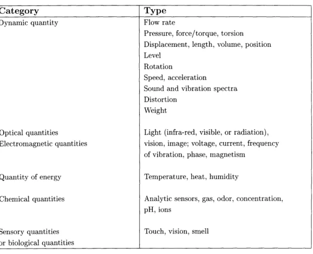
The first criterion that must be considered is the subject of measurement. Sensors range from the simple (sensors that measure a single physical quantity like force of displacement) to the complex (sensors capable of measuring sensation variables such as whether a person is in an elated or a depressed mood, or whether the 'feel' of a particular surface is pleasant or unpleasant). This is the most common method of classification whereby the sensor is classified according to the subject of measurement. Table 2.1 shows such a classification.
2.3.2
Sensors Classified by Type of Output
It is necessary to consider the type of physical quantity that is carrying the output of the sensors. This physical quantity might be an electrical quantity or a dynamic quantity. In addition, the information description format of the physical quantity is an important aspect of the output. The description format is usually an analog, digital or encoded method. Since this information is passed to a computer, it is preferable if the output be in a digital form. Data transmission from the sensor is becoming an important aspect of intelligent systems. As systems become more complicated, the type of output and its ease of transmission will become critical to the choice of sensor.
2.3.3
Sensors Classified by Accuracy
Sensor accuracy is usually expressed as the minimum detectable quantity. Accuracy is governed by the sensitivity of the sensor and the internal generated noise. A higher sensitivity and lower internal noise mean greater accuracy. For ordinary applications
an accuracy of 0.1% is sufficient. Dynamic range (full scale deflection/minimum de-tectable quantity) is expressed in decibel units and has almost the same meaning as accuracy.
Traditionally, linearity of output was important, but now as sensors become more
Table 2.1: Items classified in accordance with subject of measurement Dynamic quantity Optical quantities Electromagnetic quantities Quantity of energy Chemical quantities Sensory quantities or biological quantities Flow rate
Pressure, force/torque, torsion
Displacement, length, volume, position Level
Rotation
Speed, acceleration
Sound and vibration spectra Distortion
Weight
Light (infra-red, visible, or radiation), vision, image; voltage, current, frequency of vibration, phase, magnetism
Temperature, heat, humidity
Analytic sensors, gas, odor, concentration, pH, ions
Touch, vision, smell
intelligent, information processing by computer has reduced the importance of linear-ity.
2.4
Sensor Signal Conversion
A sensor is a primary converter that converts information about a measured phe-nomenon into a signal. This section describes signal conversion by sensors and looks at the different modes of signal conversion.
2.4.1
Signals and Sensors
The measured phenomenon is called the input signal, and the phenomenon after conversion is called the output signal. The ratio of the output signal to the input
Type Category
signal is the transmittance or gain. Passive sensors, such as water meters, obtain power from the signal source and convert this into the signal. In active sensors, such as ultrasonic flow rate meters, the input signal modulates power from another source. The former are called direct-acting conversion, and the latter are referred to as modulation conversion.
A sensor must as much as possible try to preserve the information of the input signal, that is, it must prevent lowering of the signal-to-noise ratio (SNR). A reliable sensor must have the following properties:
1. Non-interference. Changes in output should only occur due to changes in the subject of measurement.
2. High sensitivity. The gain should be as large as possible, that is, changes in output per unit change in input should be as large as possible.
3. Small measurement pressure. The presence of the sensor should not affect the conditions of the subject of measurement. In this regard, modulation conversion seems a better option than direct-acting conversion.
4. High speed. The sensor should be able to react to the maximum anticipated
rate of variation of the measured quantity.
5. Low noise. The sensor should generate the minimum amout of noise as possible. 6. Robustness. This refers to the resistance to environmental changes and/or noise. The output signal should be at least more robust than the measured quantity and it should also be easier to handle. Phenomena of larger energy are usually more robust than those of smaller energy, again, for this reason modulation conversion seems a better option than direct-acting conversion.
Sensors that have all these properties are very difficult to come across. Usually, sensors are combined with a compensation mechanism so as to limit adverse effects.
2.4.2
Signal-to-Noise Ratio
Signals must have a minimum power for successful conversion, transmission and pro-cessing. In some cases, especially with passive sensors, the output signal is weak. It is therefore necessary to increase the power of these signals by supplying energy. This is known as signal amplification. An amplifier is a signal converter (transducer) - it inputs a signal and outputs a signal of increased power. This kind of conversion is known as secondary conversion.
Eventhough amplification does increase power, the important property for the sensor is the signal-to-noise ratio. This is defined as the ratio of the signal power to the noise power, the higher the ratio the better the signal quality. The internal noise of a sensor masks any signal of a lower level. It thus determines the minimum detectable quantity, that is, the resolution, of the sensor. This is important for sensors which are required to have high quality.
2.4.3
Analog Type
The aim of many sensors is high sensitivity and high speed, sometimes at the expense of other features. In most cases, the input and output signals have a continuous functional relationship, as a result, the output is also continuous. A continuous output signal is called an analog signal. The conversion is called an analog conversion. This type of conversion usually have a higher speed and sensitivity than other systems. As a result, sensors of this type are in the majority. But there are problems associated with these kinds of sensors, some of which are [1]:
1. Resolution is limited, usually to about 0.1%.
2. They are easily affected by noise and there are problems in making them robust. 3. Before the output is passed to a computer it must be converted to digital type. Amplification is of analog type. Intelligent systems of all types incorporate a data processor of some type. Since processors are only of digital type, an analog signal
has to be converted to digital form before it can be passed into a processor. It is therefore preferable to use a digital-type sensor if one can be found of suitable speed and sensitivity.
2.4.4
Digital Type
In a digital-type signal conversion, a continuous change in the measured quantity is reflected as a stepwise or discrete change in the output signal. This output signal is encoded in the binary signals 0 and 1. An output of 1 indicates an input of 1 or more, but less than 2. Digital systems have excellent robustness; noise that is smaller than half the amplitude of the quantity that represents the 0 and 1 binary values will not affect the outputted binary value. A continuous input signal is digitized by taking readings at discontinuous time steps. This is known as sampling.
There is an advantage to using digital-type sensors in that signals processed by a computer must be in digital form. The earlier the conversion, the easier it is to maintain the SNR of the signal. When conversion from analog to digital is required, a transducer (A/D converter) performs the conversion. Digital sensors, though, have lower speed and sensitivity than the analog type.
Two important quantities in digital sensors are the sampling frequency and the bit width. The former is related to the speed, the latter to the dynamic range of the sensor.
2.5
Nature of Smart Sensors
Smart sensors derive their intelligence from a microcontroller (MCU), digital signal processor (DSP), or an application-specific integrated circuit (ASIC). These technolo-gies have been developed by several semiconductor manufacturers. In order for the electrical output from the smart sensor to be interfaced to these devices, the signal has to be amplified and converted to a digital format. Currently, MCUs and A/D converters use a 5-volt power supply.
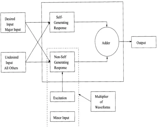
Excitation Multiplier
of Waveforms
Minor Input
Figure 2-1: General Transducer Model
Figure 2-1 [2] shows a generalized model for a transducer. The model shows that sensors are subject to interference from several undesired sources. Factors like tem-perature, humidity, and vibration must be taken into account in the design of a transducer. Traditionally, compensation was achieved by additional circuitry, but with better technology, compensation can be incorporated on the sensor or can be carried out by the microcontroller. Secondary input to produce an output signal is required by transducers based on resistive, capacitive, and inductive sensing elements. These are termed non-self generating transducers. Piezoelectric transducers, on the other hand, do not require excitation to produce a signal. An adder is used to boost the weak signal that is typically output by sensors.
Typical smart systems consist of three distinct components: (1) the sensor pro-vides the input to the system; (2) a controller decides on a course of action and this controller drives (3) the actuator to perform some action to maintain the system in some desired design range. Smart sensing means that typically the sensor takes over
some part of the signal conditioning process from the controller. Smart sensor models consist typically of five parts. These are the sensing element and the amplification and signal conditioning components, an analog-to-digital converter, some kind of memory and a control unit. Once the signal is in digital format it can be passed on to the control unit using any of several communication protocols.
One of the objectives in smart sensor development is to reduce the number of distinct elements through integration. Integration, by reducing the number of components and interconnections, can reduce the overall cost of the sensor itself. For example, manufacturers that use semiconductor technology for the sensing element may in-crease the value (and intelligence) by combining the signal conditioning in the same package or in a sensor module. Sensor integration (sensing plus signal conditioning) has several advantages. By incorporating integrated temperature sensing elements, integrated sensors can monitor temperature and compensate for it more easily. In addition, reducing the number of internal connections allows for better reliability. Micromachining refers to a chemical etching process that creates three-dimensional microstructures and is consistent with semiconductor processing techniques. The combination of micromechanical structures, sensing elements and signal conditioning will allow the design of more complex control systems and new applications that were previously too expensive for commercial applications.
2.6
Sensing Element Technologies
This section will briefly look at the nature of piezoresistive, capacitive and piezoelec-tric sensors.
2.6.1
Characteristics
The sensing technology used depends, among other things, on the accuracy required, the range of the measurand, environmental considerations that affect packaging and the reliabilty of the sensor, the dynamic nature of the signal, and the effect of other
inputs on the measurand. The environmental considerations include operating tem-perature, chemical exposure, and media compatibility. Choosing a sensor technology requires an understanding of the fundamental design principle of the sensor.
2.6.2
Piezoresistive Sensors
Piezoresistivity is the change in resistance of a material when it is mechanically stressed. Traditional sensors consisted of a Wheatstone bridge whose resistance var-ied due to an applvar-ied pressure. Newer sensor technology involves integrated silicon pressure sensors, where a pressure applied to a diaphragm changes the size of the di-aphragm and hence produces a change in resistance, which, in semiconductor material is a second-order effect. The primary effect is a change in the conductivity. Silicon processing techniques allow the design of a unique piezoresistive device. This is one of the advantages that semiconductor technology brings to sensing. In addition, the technology simplifies the additional circuitry needed for calibration and temperature compensation. Piezoresistive sensors are the most common micromachined sensors since the output is predictable and the signal easy to condition.
2.6.3
Capacitive Sensors
These typically involve a fixed plate and a moving plate. The moving plate's move-ment is due to an external phenomenon. The total effective capacitance between the diaphragm and the reference plate is given by [3]:
= dx[1I C (2.1)
where Cp is some parasitic capacitance,s is the zero pressure separation between the diaphragm and the reference plate, co is the dielectric constant in the cavity, and w(x, y) denotes the diaphragm deflection in the z-direction. Capacitive pressure sensors can be found in the automotive industry where they are based on silicon and ceramic capacitors.
2.6.4
Piezoelectric Sensors
A piezoelectric sensor produces a change in electrical charge when a force is applied accross the face of a crystal, ceramic, or piezoelectric film. Lead zarconate titanate
(PZT) ceramic is used to construct biomorph transducers that are sensitive to motion, vibration, and acceleration. They can also be activated by an applied voltage. Other types include piezofilm sensors which provide a cheap way to enable vehicle detection. The polymer film generates a charge when deformed. When placed in the pavement, the sensor outputs a signal that depends on both the speed and the weight of the
passing vehicle.
2.7
Characteristics of Smart Sensor Technology
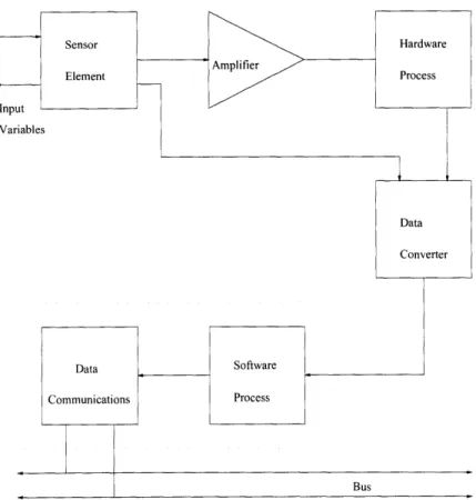
There are a number of reasons why the need for smart sensors has increased over the last few years. Among these are the increasing number of physical and chemical variables that need to be sensed, thus leading to a larger processing load as the behavior of these variables becomes less ideal. As industry progresses, the growing scale of measurement systems has grown thus leading to a greater requirement for compensation and signal processing techniques that will overwhelm even the most powerful processing facilities. Hence, the smart sensor concept has two basic driving forces: the need to deal with the non-ideal behavior of sensor mechanisms and the need to ease communication within the system. This section will look at the sub-systems within a typical smart sensor. Figure 2-2 [3] shows the essential elements of a smart system and should be referred to when reading the following subsections.
2.7.1
Primary Sensing Element
These are divided into two classes depending on the primary measurand: a chemical species and a physical process. The latter type have been more successfully incorpo-rated into integincorpo-rated microsensors and include heat, flow, pressure, acceleration and electromagnetic radiation. The success of the this kind of sensor over the chemical
Figure 2-2: Essential Elements of a Smart System.
species is due in some part to the packaging that accomodates the elements. For physical processes, the packaging allows only selective diffusion of the physical sur-rounding and at the same time provides a barrier to all chemical phenomena. For the chemical sensors, this is not possible, at least one chemical agent must be allowed to pass through for detection by the sensing element. This transfers the burden of selectivity from the sensing element to the packaging that houses the element. The sensing element is that part of the sensor where primary transduction occurs,
therefore, it is critical for designer to ensure proper design and functioning of this element. Miniaturization of sensors has not significantly affected the transduction mechanism, but sensitivity issues that were not important on the macro scale have become significant on the micro level. One example is the increase in significance of viscous damping that occurs due to very small spaces that fluid must flow through. Another important consideration is compatibility. Compatability ensures that contra-dicting technologies are not used in the sensor fabrication process. For example, solid
state sensors require high temperatures which would destroy organic membranes. In summary, the following points are important in any microsensor design [4]:
1. The sensing transduction mechanism should be understood.
2. The design of the sensor should consider the interrelationship between the var-ious components in the sensor package, including encapsulation.
3. There are some problems that arise in scaling macrosensor technologies into the micro world, and these should be considered in any design.
4. Technologies that maintain process compatibility should be chosen, otherwise it is better to isolate and compartmentalize those that do not.
Physical variables in the real world tend to appear in pairs; potential variables and flux variables. Their products represent an energy and their ratio an impedance. Examples of such pairs are voltage and current, and temperature and heat flow. A primary sensor element converts one of these pairs into another pair. The goal of the primary sensor is such that the response to a specific external variable is maximized while those of the rest are minimized.
2.7.2
Amplification
The electrical output from the sensing element is usually low and, hence, some form of amplification is required. Noise generation during amplification can be a serious problem. Circulating currents in a sensor amplifier circuit can produce an internal voltage that can cause failure. Use of a differential amplifier avoids the problems associated with the circulating current. Several kinds of ICs exist that can be used to amplify output signals in sensor circuits, a brief description of some of them can
2.7.3
Digital-to-Analog Conversion
This step represents the conversion of data from the continuous real world to the discretized world of the processor. The process is a non-linear one and is a potential source for serious distortion. The aim of sensor designers is for the A/D conversion to be an inherent part of the sensor; this can be achieved by on-chip conditioning, and will prove to be considerably cheaper than current sensors that require additional circuitry for the A/D conversion.
Some important considerations in A/D conversion are the conversion resolution, con-version accuracy, concon-version speed or bandwidth, inherent system noise level, and power consumption. The tradeoff between these factors will determine the kind of conversion architecture that will be employed.
2.7.4
Signal Conditioning
Signal conditioning (or compensation) within the smart sensor is important in re-ducing the amount of processing that must take place at the central processing unit. Some of the factors that must be addressed are [1]:
* Non-linearity * Noise
* Pick-up (interference, cross-talk) * Frequency (time) response * Drift
* Cross-sensitivity
Non-linearity used to be a problem, but now with neurological- and parallel-based
processing computing technology it has become a less serious issue. Noise and
pick-up, on the other hand, refer to any unwanted signal. Signal conditioning itself is a
problems associated with noise.
An important issue regarding the sensing element is the time response. If another signal occupies the same time of frequency frame as the measurand, some form of compensation is necessary. One approach to achieving frequency compensation is the use of a filter whose behavior is the inverse of that of the sensing element; that is, a pole for every zero and a zero for every pole. Digital filters are considerably easier to implement than their continuous counterparts, but have a problem with real time processing. As a result, considerations of which method to use are dependent on bandwidth considerations.
Drift is caused by changes in the sensing element, which are brought about by ageing
and oxidation, for example. Leakage of charge and other changes in the physical variables are other causes for drift. Drift is essentially noise, and the issues of com-pensation are similar. By far the most important sensor defect is cross-sensitivity. It is caused because sensing elements are receptive to more than one kind of physical variable. The aim of any sensor is to maximize the response to the desired stimulus and minimize the response to the unwanted ones. It goes without saying that tem-perature is the most important potential for cross-sensitivity.
Several methods exist for signal conditioning. The various compensation methods can be found in [2].
2.7.5
Information Processing
A significant portion of the processing is carried out by the smart sensor. Information
is then condensed and communicated, in digital form, via the bus to the central processor. A smart sensor should be able to verify the integrity of the information it outputs to the central processor. Some of the semiconductor technologies that are available for information processing are the MCU (micro-controller unit), the DSP (digital signal processing), and the ASIC (application-specific integrated circuit). MCUs can combine microprocessor (MPU) computing capabilities, memory, a clock oscillator, and input/output capability on a single chip. In addition, a number of
modules can be integrated on the chip and these can have a significant impact on the smart sensor performance. These include on-chip A/D converters and control of some forms of interference. DSP technology has an advantage over the MCU in that it allows the real-time execution of feedback filter algorithms. With the resulting faster execution rate, DSPs are playing a larger role in control functions. ASICs use computer-aided design (CAD) tools for custom circuit designs. Mixed-signal ASICs combine analog and digital capabilities too. This allows for higher integration.
2.8
Integration
As with all facets of semiconductor technology, there is an increasing tendency towards the integration of sensors on a single chip. Currently, integration consists of placing the sensing element and some of the signal conditioning electronics on the same chip. Integrated sensor technology allows for easier monitoring and compensation for some of the problems associated with temperature. In most cases this brings about a reduced cost. Performance enhancement, though, is not always the case.
Chapter 3
Control in the Cognitive Unit
Intelligence in human beings is a creation of nature. Cognition is housed in the brain, and it receives information about the surroundings through the natural sensory mechanisms. The information is integrated and interpreted. The cognitive process then moves on to attributes such as learning, recollection and reasoning, resulting in execution of muscular control by means of a complex neural network in the central nervous system. This process of cognition and the attribute of intelligence is central to what we define as 'human intelligence.'
In an attempt to learn from nature, humans are trying to use the process of cognition and intelligence in machines. The goal is to construct an autonomous system that can function in an unstructured environment. This chapter looks at some of the ways that the cognitive unit in intelligent systems is implemented in machines.
3.1
Conventional versus Intelligent Control
The field of control is not a new one, but one that has gone through many changes over the last few decades. Between 1940 and 1960, controllers based on frequency-domain models were used in the study of linear and nonlinear control mechanisms. The period from 1960 to 1980 saw advancements in control systems and the appli-cation of state-space methods to solve more complex control problems. It also saw
(t)
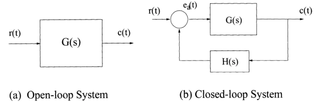
(a) Open-loop System
(b) Closed-loop System
Figure 3-1: Block Diagrams of Open- and Closed-loop Systems.
the development of the idea of observability, and theories of optimal and stochastic control. Learning, adaptability, and robustness were also introduced in this period. These methodologies relied heavily on model-based approaches.
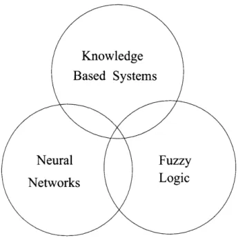
Recently, many new theories have evolved. These unite the conventional theories of control with newer techniques such as knowledge bases, fuzzy logic, and neural net-works. This emerging technology is generally described as intelligent control. Though, some of these newer developments still use the old idea of model-based control, new notions rely more on nonmodel-based control. Unlike in model-based control where the designer assumes a priori knowledge of the system, nonmodel-based control in-cludes an on-line learning mechanism which gathers knowledge through experimen-tation, identification and estimation. As in conventional control theory, feedback is playing a more important role in intelligent control. Intelligent control with com-plex feedback mechanisms is going to play a very important part in future technology.
3.2
Conventional Control
The objective of control systems is to free humans from boring repetitive tasks that can be done more easily and efficiently by automatic control devices. All automatic
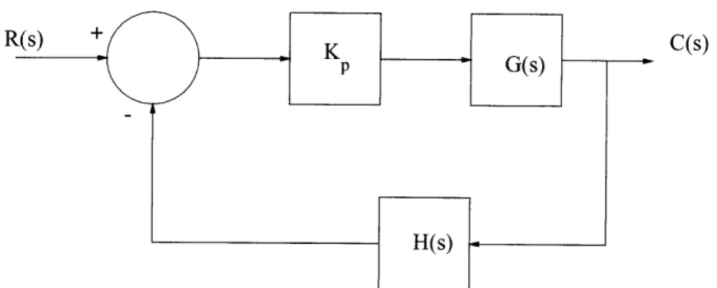
control systems are of the closed-loop type. Feedback is used to compare the reference input with the controlled output. A system without feedback is called an open-loop system. Figure 3-1 [5] shows the block diagrams of open- and closed-loop systems. For the open-loop system [5]:
C(s) = G(s)R(s)
(3.1)
For the closed loop system:
C(s)
=
G(s)Ea(s)
=
G(s)[R(s)
-
H(s)C(s)]
which gives:
G(s)
C(s) =
G()
R(s)
(3.2)
(1 + G(s)H(s)) The actuating error is given by:
Ea() (1 + R(s) (3.3)
(1
+ G(s)H(s))
This error can be reduced by making the loop gain, G(s)H(s), large over the range of frequencies of interest. Note that a loop gain close to -1 at some frequency introduces a very large error. Equations 3.1 - 3.3 use transfer function models to represent linear time-invariant continuous-time systems. Transfer function models are also referred to as frequency response models due to the interpretation of the Laplace transform variable s as a complex frequency. Because of certain basic limitations of the transform function models [5], the rest of the chapter will use a class of time-domain models known as state-space models.
3.3
Performance Criterion of Control Systems
A system must satisfy certain conditions before being used in a given application. This may involve the system response or optimization of the system in a certain way. The requirements that a system must meet are known as the performance requirements.
3.3.1
Performance Requirements
A control system is designed to meet certain performance requirements, which usually include system stability, steady-state accuracy, dynamic accuracy, and insensitivity to parameter changes. These performance requirements can be expressed either in terms of system transient response (quantities such as the maximum overshoot, rise time, settling time, damping factor and undamped natural frequency of the desired dominant closed-loop poles) or in terms of system frequency response (quantities such as the phase margin, gain margin, maximum magnification and error coefficients) or both.
If the performance requirements are expressed in terms of system transient response, then, usually, the root-locus method [4] is chosen to design the system. If they are expressed in the system frequency response, then either the Bode diagram [4] or the Nyquist diagram [4] is used depending on whether the phase gain margins are specified or the maximum magnification is specified.
3.3.2
Control System Specification
The performance of a control system can be considered in three parts: (i) the first part considers the specifications and how they directly relate to the system response;
(ii) the next part considers a performance index that is related to the error or output,
and (iii) the third part looks at the system error caused by parameter variations. The most commonly used terms to describe system specifications are peak overshoot, rise time, delay time, settling time, bandwidth, damping ratio and undamped frequency response. The terms are briefly discussed below.
Peak Overshoot
This is measured when the response has a maximum value, and it indicates the largest error between input and output during the transient state.
Rise Time
This is a measure of the speed of the response. It is defined as the time taken for the response to rise from 10% to 90% of its final steady state error.
Delay Time
This is the time it takes the response to reach some value (usually 50%) of its steady state value.
Settling Time
The settling time is the time it takes the response to decrease to and stay within a specified range (usually 2-5%) of its final value. The number of oscillations it takes to reach this value is a useful index.
Bandwidth
This is the frequency at which the output magnitude is 0.707 of the output magnitude at low or zero frequency when the system is subjected to sinusoidal inputs.
Damping Ratio
The damping ratio is the ratio of the system damping to the critical damping of a second-order system. Higher-order systems have more than one damping ratio although the damping ratio measured at the most dominant frequency is usually the most important. This is an important parameter in determining the transient performance and the stability of a system.
Undamped Natural Frequency
3.4
Performance Indices
Control system performance is measured by a performance index. It is essential to be clear what is meant by system performance. For example, an attempt may be to keep the error either constant or at a minimum. Another measure might use the square of the error. It is thus important to be clear about what it is that is required to be optimized.
For many control systems, a performance index based on the error is useful. Four
common indices that are used are [4]:
Ji = e2(t)dt (3.4)
J2 = e(t) dt (3.5)
J3 =] tle(t) dt (3.6)
fT
4
=
te
2(t) dt
(3.7)
where the upper time limit is arbitrary but often the settling time is used. In some cases infinity is used as the upper time limit. J, is the performance index based on the integral of the square error (ISE). J2 is the integral of the absolute error (IAE). J3
is based on the integral of the time multiplied by the absolute error (ITAE). Finally,
J4 is based on the integral of the time multiplied by the square of the error and is
designated as ITSE. For a minimum performance index, the ITAE and the ITSE are the most useful.
3.5
Control Types
The steady-state and transient response of a system can be modified using a controller in the control system. Controllers, in addition to modifying the steady-state and transient response, also have may bring about other changes that may be undesirable. Three general types of control that exist are:
C(s)
Figure 3-2: Proportional Control 1. Proportional Control
2. Derivative Control 3. Integral Control
The three types of controls are briefly discussed in the following sections.
3.5.1
Proportional Control
Figure 3-2 [4] shows a feedback control system that employs proportional control. In
order to keep the steady-state error and the maximum overshoot within acceptable limits, a suitable gain must be chosen. One problem that often occurs in such systems is that an optimum Kp that satisfies the steady-state error may result in a large maximum overshoot and this may result in instability in the system. Usually, this problem is overcome by using proportional control in addition with some other type of control.
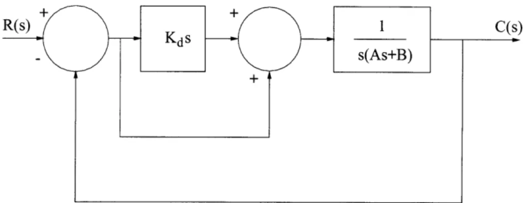
Figure 3-3: Control System with Derivative and Proportional Control
3.5.2
Derivative Control
Derivative control is employed when it is necessary to have an actuating signal that is proportional to the time derivative of the error signal [4].
M(s) = KdsE(s) (3.8)
where Kd is the gain of the controller. Equation 3.8 shows that the actuating signal,
M(s), is proportional to the error signal, E(s). Clearly, the system will not respond if
the error is constant. Hence, derivative control is used in conjunction with other con-trols. Derivative control is useful though when the aim is to increase system damping. Figure 3-3 shows a second-order control system that uses both derivative and propor-tional control. The output for this system is [4]:
C(s)
Kds + 1
R(s) AS2 + (B + Kd) + 1
Comparing Equations 3.8 and 3.9 shows that the effective damping of the combined system has increased. Because the maximum overshoot is directly related to the system damping, this control type allows control of the maximum overshoot as well.
3.5.3
Integral Control
In systems that use integral control, the signal is proportional to the integral of the error. Generally, in such systems there is usually a problem with stability if the gain is raised to high. This instability occurs because systems that use integral control usually are converted to a system that is one order higher than originally. [4] contains more on the use of integral control.
In summary, knowing the advantages of the different types of control systems allows us to combine the different types to achieve a better control system.
3.6
Feedback and the Effects of Feedback on
Con-trol
Feedback is used to reduce the error between the reference input and the system output. However, the importance of feedback extends to much more than this. Feed-back affects other performance characteristics such as stability, bandwidth, overall gain, impedance, and sensitivity. Consider, again, Figure 3-1(b) which shows a sim-plified closed-loop system, where r(t) is the input signal, c(t) the output signal, and
ea(t) is the error signal. G and H can be considered as the gains. Simple algebraic
manipulations show that the input-output relationship is: c G
S + G
(3.10)
r l+GH
With this relationship in mind, we can examine some of the effects of feedback on the performance characteristics in the following subsections.
3.6.1
Effect of Feedback on Overall Gain
Equation 3.10 shows that feedback affects the gain of an open-loop system by a factor of (1 + GH). The quantity GH itself may or may not include a minus sign. Since G and H are functions of frequency, the value of 1 + GH may be greater than or
less than 1, depending on the frequency range. Therefore, feedback can increase or decrease the gain of a system depending on the frequency range.
3.6.2
Effect of Feedback on Stability
A system is said to be unstable if the output increases without bound. Referring to Equation 3.10, it is clear that if GH = -1, the output will be infinite for any input. This is not the only condition for instability, though.
Feedback can also be used to make an unstable system stable. Suppose we are dealing with a system where GH = -1. By introducing another feedback loop through a negative feedback of F, the input-output relation will now look like this:
c G
(3.11)
r 1 +GH +GF
Thus, by introducing the outer feedback loop, F, a system unstable because GH = -1
can be stabilized, eventhough the inner loop is still unstable.
3.6.3
Effect of Feedback on Sensitivity
Since the physical elements in a control system have properties that change with age
or environment, sensitivity is an important consideration in the design of a control
system. The aim is to have a system that is relatively insensitive to the changing
parameters of the control system. Consider, again, Figure 3-1(b), and consider G as
the varying parameter. The sensitivity of the gain of the overall system to the change is G is
SM 6M/M
SG
=
(3.12)
where 6M and 6G are the incremental changes in M and G, respectively; and
/deltaM/M and 6G/G is the percentage change in M and G respectively. The
sen-sitivity, SM can be written as:
SG G (3.13) 6G/G M - 1 + GH
From Equation 3.13, the sensitivity can be made small by increasing GH, as long as the system remains stable.
3.6.4
Effect of Feedback on Noise
Physical systems are always subject to some kind of external disturbance or noise. The effect of feedback on noise depends on where the noise is introduced in the system. Though, in many cases, feedback does reduce the effect on noise on a system, no general conclusions can be made.
3.7
Feedback Control Systems
There are several methods of classifying feedback control systems. If a classification is made according to the method of analysis or design, then feedback control systems can be classified as linear of nonlinear, time-varying or time-invariant. Control systems are also classified according to the purpose of the system. There are positional control systems and velocity control systems which control the output in the way their names imply. This section looks at some of the more common ways of classifying control systems.
3.7.1
Linear versus Nonlinear Control Systems
Linear systems do not exist in the real world, but linear feedback control systems are idealized models that are created purely for analysis and design purposes. A system is defined as linear when the magnitude of the signals in the control system obey the principle of superposition. When the magnitudes of the signals extend beyond the range of linear behavior, depending on the extent, then the system can no longer be considered linear.
Linear systems have a vast number of analytical and graphical techniques for design and analysis purposes. Nonlinear systems, though, are very difficult to design and analyze, and in some cases, there are no general methods to treat a wide class of