HAL Id: hal-02089341
https://hal.archives-ouvertes.fr/hal-02089341
Submitted on 3 Apr 2019HAL is a multi-disciplinary open access
archive for the deposit and dissemination of sci-entific research documents, whether they are pub-lished or not. The documents may come from teaching and research institutions in France or abroad, or from public or private research centers.
L’archive ouverte pluridisciplinaire HAL, est destinée au dépôt et à la diffusion de documents scientifiques de niveau recherche, publiés ou non, émanant des établissements d’enseignement et de recherche français ou étrangers, des laboratoires publics ou privés.
Analytical and numerical study of the evaporation on
mixed convection in vertical rectangular cavity
Malika Ihdene, Toufik Ben Malek, Sofiane Aberkane, Mourad Mouderes,
Pierre Spiteri, Abderrahmane Ghezal
To cite this version:
Malika Ihdene, Toufik Ben Malek, Sofiane Aberkane, Mourad Mouderes, Pierre Spiteri, et al.. Analytical and numerical study of the evaporation on mixed convection in vertical rectangu-lar cavity. Fluid Dynamic and Material Process, Tech Science Press, 2017, 13 (2), pp.85-105. �10.3970/fdmp.2017.013.085�. �hal-02089341�
Any correspondence concerning this service should be sent
to the repository administrator:
tech-oatao@listes-diff.inp-toulouse.fr
This is an author’s version published in:
http://oatao.univ-toulouse.fr/22703
To cite this version:
Ihdene, Malika and Ben Malek, Toufik and
Aberkane, Sofiane and Mouderes, Mourad and Spitéri, Pierre and
Ghezal, Abderrahmane Analytical and numerical study of the
evaporation on mixed convection in vertical rectangular cavity. (2017)
Fluid Dynamics and Materials Processing journal, 13 (2). 85-105.
ISSN 1555-256X
Official URL
DOI :
https://doi.org/10.3970/fdmp.2017.013.085
Open Archive Toulouse Archive Ouverte
OATAO is an open access repository that collects the work of Toulouse
researchers and makes it freely available over the web where possible
Analytical and Numerical Study of the Evaporation on Mixed
Convection in aVertical Rectangular Cavity
M. Ihdene1, T. Ben Malek2, S. Aberkane3, M. Mouderes4, P. Spiterri5and A. Ghezal2
Abstract: We consider an ascending laminar air flow in a vertical channel formed by two parallel flat plates wetted by a thin water film and under different temperature and concentration conditions. The study includes a numerical finite volume method for the treatment of the double diffusion problem, where the analytical solution is given to the thermal diffusion. The analytical study showed that the reversed flow is observed only under some wall temperature conditions and also for certain values of Re/Gr. The
reversed flow is also strongly dependent on the aspect ratio A, which is based on the
cross section of the channel.
Indeed, the results show than this dependence is very strong for values less than a certain critical one equal to 2.22. In the absence of the mass transfer the results showed that the evaporation rate remains null along the channel, decreases when the mass gradient is favorable and it finally vanishes at x=15. However, the evaporation rate increases in the
case of an unfavorable mass gradient, to cancel at position x=20, then merges with the
curve representing the forced convection. In the absence of heat transfer the evaporation rate is less important and amounts to fifty percent of the double diffusion. The results obtained by the analytical and numerical methods are compared each other and with those of a similar works and a good agreement was found.
Keywords: Heat and mass transfer, mixed convection, numerical and analytical study, channel flow.
1 Introduction
The double diffusion effects on the dynamic and thermal behavior of a real fluid flow has been widely studied as in the work of Cheng Chin-Hsiang and Weng Chun-Jen (1991). They also treated the effect of the geometry on the reversed flow in a vertical differentially heated channel. Their results showed that the presence of the reversed flow
1Université Yahia Farès de Médéa-26000, Algérie.
2Laboratoire de mécanique des fluides théorique et appliquée, Faculté de physique, Université des sciences et de la technologie Houari Boumediene Bab Ezzouar, Alger, Algérie.
3Département Génie mécanique, Faculté des sciences de l’ingénieur, Université Mohand El Hadj Bouira, Algérie.
4Faculté des hydrocarbures et de la chimie, Université M’Hamed Bougara de Boumerdés-35000, Algérie. 5Université de Toulouse, France.
depends on the geometry and on the ratio Re/Gr. Podvin and Le Quéré (2013) studied numerically a confined flow between two vertical plates which are differentially heated in the presence of a positive stratification with periodic wall temperature conditions. The results showed that instabilities appear for certain values of Ra. This bibliographic work reveals two main axes, one of them is restricted to the effect of the temperature gradient. Belhadj M, Orfi, Debissi et al. (2007) investigated numerically the problem of condensation by mixed convection in a vertical channel. The channel plates are subject to uniform heat fluxes. The results showed that the increasing vapor concentration induces an increase in the condensing rate, and consequently the bulk temperature of the humid air becomes larger. Laminar mixed convection of a binary gas mixture in a parallel-plate channel has been analyzed by Kiari Goni Boulama et al. (2012) with a numerical method for the steady state case. The channel wall undergoes different combinations of thermal and solutal boundary conditions. Analytical solutions have been found for the main flow. A criterion based on the Grashof and Reynolds numbers, and the channel inclination for the presence of a reversed flow has been observed. As regard to the studied geometrical configurations we mention the rectangular or the cylindrical cavities in either horizontal or vertical position. Nasr, Debbissi and Ben Nasrallah (2010) carried out numerical investigations about the evaporation of a thin binary liquid film by forced convection inside a two parallel plate channel. The results show that the temperature inversion is obtained during evaporation for the high concentrations of the binary liquid mixture. The case of two flat plates constitutes a classical problem since the work of Rayleigh-Bénard. Sergent, Podvin, Xin et al. (2011) studied numerically the natural convection instabilities of the bi-periodic air blade which is confined between two vertical plates. Two cases are considered: In the first case, the temperature on each wall is constant and in the second case a constant stratification at the walls is imposed with a linear increase of the temperature height. The results are compared with the previous 2D simulation. 2D transverse rolls are observed in both cases and they are simply stationary in the isothermal case and oscillatory in the stratified one. Cherif, Kassim, Benhamou et al. (2011) carried out an experimental and numerical study on mixed convection with heat and mass transfer in a vertical rectangular duct. Two walls are wetted by a film of water and maintained at a constant heat flux while the others are dry and thermally insulated. The results showed that evaporation occupies mostly the walls surfaces. The effects of buoyancy force on an upward steady state fully developed laminar flow of humid air in a vertical parallel-plate channel was studied numerically by Oulaid, Benhamou, Galanis, (2010). A significant effect of the buoyancy forces has been observed on the hydrodynamic, thermal and mass fraction fields. Additionally, these forces induce flow reversal for high air temperatures and mass fractions at the channel entrance and reduce heat and mass transfer. The conditions for the existence of reversal flow have been determined for different aspect ratio and mass diffusion Grashof numbers. Senhaji, Feddaoui, Mediouni et al. (2009) performed numerical study of evaporation in mixed convection of pure ethanol and methanol liquid film. They obtained a system of equations using implicit finite difference methods which are solved by the TDMA schema. They examined, also, the influence of the entering liquid, the Reynolds number within the gas flow and the heat flux at the wall, on the heat and mass transfer intensity. A comparison between the
obtained results for alcohol and water is studied under the same conditions. The turbulent hot air flowing downward a vertical channel is cooled by a laminar liquid film on both sides of the channel with thermally insulated walls. The effect of gas-liquid phase coupling, variable thermophysical properties and film vaporization are considered. Using an elliptical formulation Ait Hammou, Benhamou, Galanis et al. (2003) investigated numerically the effects of simultaneous cooling and mass transfer of the laminar humid air flow downward a vertical channel with wet walls. They showed that the axial velocity profiles, the friction factor, the sensible Nusselt number and the Sherwood number are significantly influenced by buoyancy force. The friction factor and Sherwood number increases with both inlet air temperature and inlet air humidity.
The axial evolutions of the interface transverse velocity, the average air temperature, the average steam mass fraction, the Nusselt number, the latent heat, the friction coefficient and the Sherwood number are analyzed for different inlet air conditions.
The effects of buoyancy forces on the hydrodynamic behavior are very important; however, their influence on the average air temperature and the average mass fraction is low. Knowing that the heat is always transferred from the air to the walls, the latter must be heated when evaporation is significant. If evaporation is slow or condensation is present, walls cool down. Chien-Chang Huang (2005) examined numerically mixed convection heat and mass transfer in vertical ducts with film evaporation and condensation. The effect of film evaporation and condensation along the wetted wall with constant temperature and concentration on the heat and mass transfer in rectangular vertical ducts are considered. The results showed that the latent heat transport with film evaporation and condensation enhances the heat transfer rate. Better heat transfer enhancement related to film evaporation is found for a system with a higher wall temperature. Agunaoun, Idrissi, DaÏf et al. (1998) proposed a numerical analysis of the heat and mass transfer in a binary thin film flowing down an inclined plane. This analysis is based upon the resolution of transfer equations in liquid and vapor phases by an implicit finite difference method. These equations are coupled and the mass diffusion in the liquid film is taken into account. The most interesting results are obtained in forced convection, particularly in the case of ethylene glycol-water mixture. Lefi1 and Boukadida (2008) studied mechanisms of heat and mass transfer of evaporation in forced convection, without liquid film, in the case of a steady established regime. The in-time monitoring, i.e. in unsteady phenomena, of the different processes and magnitude, can give better understanding of the mechanisms of coupled heat and mass transfer during the evaporation of a liquids in a confined space at the free surface level. This work provides a contribution to the understanding of these mechanisms in unsteady forced convection during the evaporation of a liquid in a horizontal channel. The flow is laminar and two-dimensional. The gas mixture is transparent to thermal radiation. The method of finite difference is adopted for the numerical solution of the different conservation equations. Their paper depicted the evolution of different spatial physical quantities such as temperature, vapor concentration, longitudinal and transversal components of the fluid velocity. They also presented the evolution of local heat and mass transfer coefficients and the evolution of the Nusselt and Sherwood numbers. Nait Alla, Feddaoui, Meftah (2015) presented a contribution to the comprehension of
diffusion mechanisms in unsteady forced convection during evaporation of certain liquids in a horizontal channel. They analyzed the mechanism of mixed convection with heat and mass transfer during the evaporation of ethanol liquid film over vertical finite channel. A method of implicit finite difference is used to solve the coupled equations of the liquid film and gas associated to the corresponding interface conditions. The effect of the number of heated zones and their positions on the heat and mass transfer is analyzed. Recently, Terzi, S. Ben Jabrallah et al. (2016) realized an experimental study concerning the porosity effect on the evaporation. The results showed that the temperatures are higher with the presence of the porous medium and also the addition of the porous layer improves heat and mass exchange.
The main objective of this work is to analyze the heat and mass transfer during the evaporation of an extremely thin liquid film by mixed convection of humid air in a vertical channel with isothermal wet walls. An analytic study was developed in order to clarify the conditions under which, in developing flow regions, reversed flow does occur for different heating conditions.
2 Analytical study
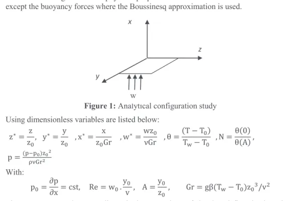
This study concerns the analytical analysis of a fully developed upward flow coupled with heat transfer in a vertical rectangular conduct of a differentially heated walls as shown in the Figure 1. The physical properties of the fluid are considered constant except the buoyancy forces where the Boussinesq approximation is used.
Figure 1: Analytical configuration study Using dimensionless variables are listed below:
z∗= z z", y ∗= y z" , x ∗= x z"Gr , w ∗=wz" νGr , θ =(T − TT&− T"") , N = θ(0) θ(A) , p =('*'+)-+. /123. With: p"=∂p∂x = cst, Re = w" .yv , A =" yz" " , Gr = gβ(T&− T")z" 7/v9
The momentum and energy dimensionless equations of developed flow in the mixed convection are written in the following form:
z x
y
:.; :-. +: .; :>. =:':?− θ (1) w:@:?= 1/ Pr C::>.@.+: .@ :-.D (2)
2.1 Temperature equation resolution
Assuming that the temperature is independent of the x direction, the temperature equation becomes:
:.@
:-.+: .@
:>.= 0 (3)
The solution of the equation (3) is:
θ(z, y) = θ"eE(FH-IEFH>)= θ"eEF-eF>= sin(kz + φ-)( Cch(ky) + D sh(ky)) (4)
Where: φ-, C, D are determined from the following boundary conditions
M = 0 θ = 0 , z =1 θ=0 (5)
y = 0 θ = 1 , y =A θ=N (6)
As:
φ-= 0, k = mπ, C = 1, D =Q*SUFVWU(FV) (7)
The general solution is expressed as the form:
θ(z, y) = ∑Y Gm
Z[\ θ"eE]FH-IF^>_ (8) The standard temperature expression is:
θ(z, y) = ∑Y 9(\*(*\)a `)
Z[\ θ"eE]FH-IF^>_ (9)
Limited to the first term of the harmonic solution, i.e. m = 1, we found the temperature final expression which is corresponding to the particular solution:
θ =abWU[a(V*>)]IQWU(a>)WU(aV) ∙ sin(πz) (10)
2.2 Resolution of the momentum equation
The velocity equation is given by:
:.&
:-.+: .&
:>. =:':?− θ (11)
The folowing solution is adopted for the equation (11):
w = w\C:':?D + w9(θ) (12)
With:
:'
:?= Cte et θ = θ(z, y)
Then, the differential velocity equation can be decomposed into two equations:
∇9w\=:'
:? , ∇9w9= −θ(z, y) (13)
Then, is calculated with the equation below:
:.&o
:-. +: .&o
The solution of the equation (14) may be given in the flowing form:
w\(z, y) = w\(z) + :':?. wqqqq(z, y)\ (15)
The solution (15) is replaced in the eqt (14):
:.&o(-) :-. +:':?C: .&qqqq(-,>)o :-. +: .&qqqq(-,>)o :>. D =:':? (16) The precedent equation (16) is possible only if:
:.&o(-) :-. =:':? and : .&qqqq(-,>)o :-. +: .&qqqq(-,>)o :>. = 0 (17) We found that: w\(z) =:':?C -. 9 + C\z + C9D (18)
The constants C\andC9 are determined by the application of the boundary conditions:
z = 0, w\= 0 → C9= 0 and for z = 1, w\= 0 → C\= −12∂p∂x
So, W1 is: w\(z) =\
9 :'
:?(z9− z ) (19)
The calculate of the average velocity wqqqq(z, y) is:\
:.&qqqq(-,>)o
:-. +: .&qqqq(-,>)o
:>. = 0 (20)
The solution of the eqt (20) is assumed to be:
w•\(z, y) = w•\"eE]FH-IF^>_= (Cch(ky) + Dsh(ky))sin (kz + φ-) (21)
Appling the precedent boundary conditions, which ones we found that: k = π, φ-= 0
The particular solution is now:
w•\(z, y) =WU(FV*F>)IWU(F>)WU(FV) sinkz (22)
The general solution is presented here by:
w•\(z, y) = ∑YZ[\Gmw•\"eE]FH-IF^>_ (23)
Then the velocity expression for the first harmonic is:
w•\(z, y) =ab‚WU[a(V*>)]IWUa>WU(aV) ∙ sin(πz) (24)
Similarly the velocity w9 is calculated following the steps below:
:.&.
:-. +: .&.
:>. + θ(z, y) = 0 (25)
with θ =„4sh[π(A − y)] + Nsh(πy)sh( πA) ∙ sin(πz)
The general solution of the velocity is given in the equation:
w9(z, y) = ∑YZ[\Gm/2mπ[C\ch(mπy) + C9sh (mπy) + y(C7ch(mπy) +
In the case of taking into account only the fundamental harmonic, (G\=ba ) , the expression becomes:
w9(z, y) = 2/π9[c\ch(πy) + c9sh (πy) + y(c7ch(πy) + cbsh (πy))]sin (πz) (27)
Applying the boundary conditions of the velocity we find that: w9(z, y) =a.WUaV9 …ych(π(A − y) − A CWU (a>)WU(aV))D† sin (πz) +
9Q
a.WUaV…−A C(SU(aV)WU(a>)WU(aV) )D + yNch(πy)† sin (πz) (28)
It can be write in the following form:
w9(z, y) = w9"(z, y) +a.WUaV9 …−A C(*QSU(aV)WU(a>)WU(aV) )D − yNch(πy)† sin (πz) (29)
Where: w9"(z, y) =a.WUaV9 …ych(π(A − y) − A CWU (a>)WU(aV))D† sin (πz)
represents the velocity, when only one of the walls is heated; in this case; the right side is in the temperature θ (0) = 1 and the left side is in the ambient temperature θ (A) = 0, as it was the case of the study by Cheng Chin-Hsiang and Weng Chun-Jen (1991).
2.3 Expression of the velocity as a function of a grashof number
The expression of (the) velocity contains the pressure gradient (∂p/∂x), we must (then) calculate it according to the Gr and Re number. For this we calculate the flow rate of this velocity through a transverse section of elementary surface equal to dz.dy as follows:
∬ wV ∗dzdy
>[" =ˆ‰>23 = f(:':?) (30)
It gives: :':?= g(ˆ‰>23) (31)
This expression indicates that the pressure gradient of according to x direction is constant for a given flow in a given geometry. It depends only on the values of Rey/Gr and A. The calculation of the integral is then:
∬ w∗dzdy = b
aŠSU(aV)*\)WU(aV) …\IQa +V( QSU(aV)*\)WU(aV) † −bQVaŠ −‹'‹?…\9V −\Œa•SU(aV)*\)WU(aV) † =ˆ‰>23 (32)
Where: −‹'‹?=C
Ž•^
•‘*’ŠŠ“”(’•)–o)—”(’•) …o˜™’ I•( ™“”(’•)–o)—”(’•) †IŠ™•’ŠD
…o.•*’•oš“”(’•)–o)—”(’•) †
So the velocity expression is given by:
w(z, y) =*
Ž•^
•‘IŠ (“”[’•]–o)’Š—”(’•) …™˜o’ I•(™“”(’•)–o)—”(’•) †*QŠ•’Š • o.*’•oš(“”(’•)–o)—”(’•) › \ 9(z9− z) + b
a‚WU[a(V*>)]IWUa>WU(aV) ∙ sin(πz) œ +
9
a.WU(aV)…WU(aV)*V sh(πy) + ychπ(A − y)† sin(πz) +a.WU(aV)9Q …V(SU(aV))WU(aV) sh(πy) −
ych(πy)† sin(πz) (33)
We note that these last two expressions are identical to those given by Cheng Chin-Hsiang and Weng Chun-Jen (1991) by replace N = 0.
The wall friction is given by: τ&=dwdyž
>[V= C Ÿ
4
π9chπA − 1sh(πA) +π9sh(πA) Ÿ2 sh(πA) ch (πA) + 1 +– Aπ π9sh(πA)2N
…Va(SU(aV))WU(aV) ch (πA) − ch(πA) − Aπsh(πA)† (34)
Where: C =*
Ž•^
•‘IŠ (“”[’•]–o)’Š—”(’•) …™˜o’ I•(™“”(’•)–o)—”(’•) †*QŠ•’Š •
o.*’•oš(“”(’•)–o)—”(’•) That can be writing in the following form:
τ&= ¢ˆ‰>23 −b (SU[aV]*\)aŠWU(aV) …a\−WU(aV)V +Qa+V]QSU(aV)_WU(aV) † + NbVaŠ£ –Š ’.…o˜“”(’•)—”(’•) † • o.*’•oš(“”(’•)–o)—”(’•) − 9
a.WU(aV)…WU(aV)*VaSU(aV)WU(aV) † −a.WU(aV)9Q …Va*WU(aV)SU(aV)WU(aV) † (35)
We put: −¤ =
–Š
’.…o˜“”(’•)—”(’•) † •
o.*’•oš(“”(’•)–o)—”(’•)
andQ = −b(*¦)(SU(aV)*\)aŠWU(aV) …a\−WU(aV)V † −a.WU(aV)9 …1 −
VaSU(aV) WU(aV) †
The final expression of the wall friction in the case 1, becomes:
τ§+= −Mˆ‰>23 + Q (36)
This expression shows that the wall friction decreases linearly with Rey/Gr parameter. The supplementary term of the wall friction due to the existence of a temperature at the right wall is given by an additional term defined by:
τW©'= N ª¢−b (SU[aV]*\)aŠWU(aV) …a\+V(SU(aV))WU(aV) † +bVaŠ£ (−M) −a.WU(aV)9 …Va*WU(aV)SU(aV)WU(aV) †« (37)
We find: τW©'= NP, Which then gives the final expression of the wall friction in the
general case:
τ&= −M Rey Gr¬ + Q + NP (38)
2.5 Reverser flow
This situation exist for the annulations of the wall friction, -®= ¯, which corresponds to
the critical Re/Gr values given by
ˆ‰>
23 S3°±°²©‰= −N bV
aŠ+b (SU[aV]*\)aŠWU(aV) …QI\a +V(QSU(aV)*\)WU(aV) † −\9¢…WU(aV)*VaSU(aV)WU(aV) † + N …Va*WU(aV)SU(aV)WU(aV) †£ ∗o.•*’•oš(“”(’•)–o)—”(’•)
\ISU(aV) (39)
3 Problem formulation and numerical study
We consider the following hypothesis; humid air is considered a perfect gas, the viscous energy dissipation and The Soret effects and Dufour ( ? ) are negligible, Boussinesq approximation is adopted, the liquid gas interface is considered on thermal equilibrium and the surface shear is inexistent. In this case the momentum and energy equations can be written as follow: · Continuity equation: :³ :? + :´ :>= 0 (40) · Momentum equation: u:?:©+ v:©:>= −:¶:?+ˆ‰9 C::?.©.+: .© :>.D +ˆ‰9.(G·θ + Gr¦C) (41) u:?:¸+ v:¸:>= −:¶:¹+ˆ‰9 C::?.¸.+: .¸ :>.D (42) · Energy equation: u:@:?+ v:@:>=ˆ‰¶39 C::?.@.+: .@ :>.D (43) · Species conservation equation:
u:S:?+ v:>:S=ˆ‰ºS9 C::?.S.+: .S :>.D (44) Boundary Conditions: At the inlet y = 0 v = 1 et u = c = θ = 0 (45) At the outlety = L :©:>=:¸:>=:@:>=:>:S= 0 (46)
At the walls: x = 0 and x = 0.5 u = ∓u‰ C = ¾ = 1 (47)
The dimensionless transverse velocity at the interface is given by: (Burmeister, 1993) U‰==ˆ*9 •ºS (&À*&ÁÂ) (\*&À) :à :?Ä?[" (48)
The mass fraction w& at the wall, corresponding to the saturation conditions at Twis
calculated by assuming that the air-vapor mixture is an ideal gas mixture.
3.2 Numerical method
The numerical approach adopted is based on spatial discretization by the finite volume method developed by PATANKAR (1980). The velocity-pressure coupling is treated with the SIMPLER algorithm. For the calculation of the velocity fields it uses a shifted grid in relation to the pressure field. The convergence criterion is based on the residue of the continuity equation. It is reached when this residue is less than a predetermined value
usually taken equal to 10-6.
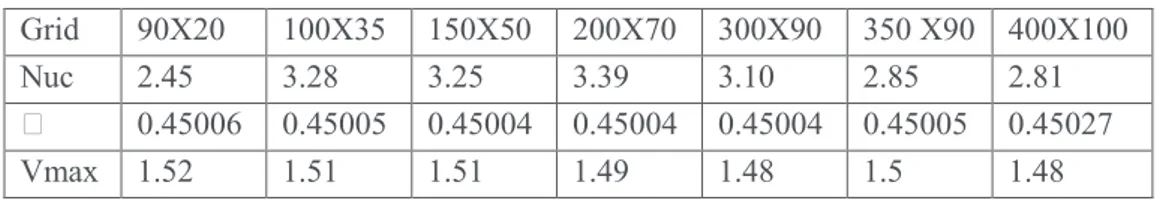
3.2.1 Grid independence study
We consider a non-uniform grid in both directions with greater node density near the inlet and near the walls; where the temperature and concentration gradient are high. In
order to study the sensibility we considered different grid (90×20, 100×35, 150×50,
200×70, 300×90, 350×90, and 400×100). The results of this study are obtained by
comparing the values of the Nusselt number near one of the walls, the maximum of the stream function and the transverse velocity. The table 1 shows that the results of this
study. the both grid 100×35 and 200×70 are chosen in this study, On the other hand, the
computer code and the mathematical model have been validated by comparison with the available results in the literature (Shah and London (1978); Ait Hammou (2004); Cherif (2010)).
Table 1: Grid independence results (Grt=-88000 and Grs=10700)
Grid 90X20 100X35 150X50 200X70 300X90 350 X90 400X100
Nuc 2.45 3.28 3.25 3.39 3.10 2.85 2.81
• 0.45006 0.45005 0.45004 0.45004 0.45004 0.45005 0.45027
Vmax 1.52 1.51 1.51 1.49 1.48 1.5 1.48
3.2.2 Code validation
To check the validity of the calculation code that we have and that it can simulate the flow in mixed convection with heat transfer and mass. We compare our results with those of Oulaid, Benhamou, Galanis (2010), in the case of the evaporation of an extremely thin film in a vertical channel for five different thermal and solutal boundary conditions. We represent in Figure 2, a comparison of the streamlines for different cases, it illustrates the effect of buoyancy forces. On the other hand the Figure 3 shows comparison of the transverse vapour velocity profiles. Finally, the Figure 4 shows a comparison of the axial evolution of the friction factor. These results are in good agreement between our results and those of previous works. The agreement between these results allows us to ensure the validity of our Code concerning the study of this type of flow.
4 Results and discussions
The results are presented for an air-steam mixture with several wall conditions Tw=20°C,
Cw=14.5g/Kg, Pr=0.71, Sc=0.56 and Re=300. The values of (the) parameters of the study
are presented in Table2.
Table 2: parameters of the study
Case 1 2 3 4 5
Gr· -0.88 105 -1.71 .105 -2.29 .105 -1.71 .105 -1.71 .105
GrZ 1.07.104 0 1.29.104 -104 +104
Figure 2(a): Stream lines.Present study Figure 2 (b): Stream lines. Oulaid study For different thermal and solutal boundary conditions and when the two walls are identically heated, the rate of evaporation along the cavity is shown in Figure 2. It is noted that in the absence of mass transfer, evaporation rate Figure 3a, b remains null along the channel. The velocity decreases along the line in the case of a favorable mass gradient to cancel at position x=15. It shows an unfavorable mass gradient to cancel a position x = 20. It merges with the curve representing the forced convection. In the immediate neighborhood of the entrance zone, we notice a small difference between both curves in the velocity where the evaporation rate is more important see Figure 4a, b.
When the two walls are identically heated; T\= T9,the streamlines are axis symmetric in
Figure 5.
Figure 3: Comparison between our (the authors) results and those of [Oulaid, Benhamou and Galais (2010)] for the transverse vapour velocity for different Grashof numbers y x 0 0.2 0.4 0 5 10 15 20 25 y x 0 0.2 0.4 0 5 10 15 20 25 y x 0 0.2 0.4 0 5 10 15 20 25 0 5 10 15 20 25 -0,00050 -0,00025 0,00000 0,00025 0,00050 U e X
Oulaid and al (2010) Present results Gr M=0 GrM=-10000 GrM=10000 0 5 10 15 20 25 -0,0010 -0,0005 0,0000 0,0005 0,0010
Oulaid and al Present results Gr
T=-0.88E05 and GrM=1.07E04
Gr
T=-1.71E05 and GrM=0
Gr
T=-2.29E05 and GrM=1.29E04
Forced Convection
U
e
Figure 4: Comparison between our (the authors) results and those of [Oulaid, Benhamou and Galais (2010)] for the axial evolution of the friction coefficient.
We note a vortex region in the vicinity of the hot wall it disappears completely in the direction of the cold wall.
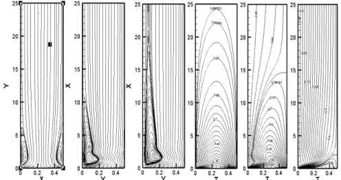
Figure 5: Stream lines and isothermal lines for different temperature cases Å9=1,0.8,0.1. This fluid recirculation zone spreads out as the temperature of the right wall decreases. In the other hand when the right wall is at a higher temperature, the isotherms in Figure 5 detach increasingly more and more from the cold wall to give rise to a developing laminar distribution. They are almost parallel, in the case where the right wall is almost
at zero temperature (T9= 0). 0 5 10 15 20 25 -15 0 15 30 f.R e X
Present results Oulaid (2010) GrM=-10000
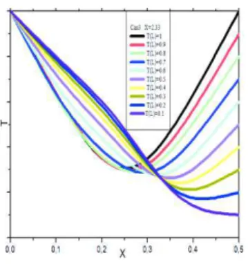
Figure 6: Radial profile of temperature
The radial temperature profile in Figure 6 indicates a total symmetry when the two walls are identically heated. However, it is found that the minimum of the curve T (y) moves toward the cold wall as this latter is gradually less heated.
It is noted also that this minimum decreases with temperature T9. Beyond a certain
value (T9= 0.1 ) the temperature profile loses completely its symmetry and the curve T
(y) presents an inflection point. This situation reveals the presence of thermal instabilities in the flow.
4.2 Axial velocity profile
If the two walls are identically heated, the radial velocity profile has a Poiseuille profile with a symmetrical reversed flow near the hot walls as shown in Figure 7
This symmetry disappears gradually as the right wall is less heated, leading to a completely asymmetrical profile with a displacement of the maximum velocity towards
the cold wall. The value of this maximum decreases for T2higher than 0,7. Beyond this
value the maximum begins to increase. It should be noted that the reversed flow is
entirely absent in the cold region, when T2is less than 0.9. In contrast, at the hot wall the
reversed flow is accentuated when the temperature T2decreases.
A reversed flow exists on the hot wall and this is due to the presence of intense buoyancy forces. The area concerned by this flow is located at the entrance of the conduct and it is as much more extended toward the outlet as the difference in temperature of the walls is large. This aspect is confirmed by the radial profile of the velocity which is shown in Figure 7 where the negative values of the velocity are located near to the hot wall and also are more important as the temperature difference is large. This causes a decrease in the velocity. This decrease is compensated by an increase in its value beside the cold wall in order to keep the flow rate conservation.
Figure 7: Radial profile of velocity
The analytical study showed that the velocity of the flow is composed of two terms;one
of them is a function of the pressure gradient and the temperature,and the other is
dependent on temperature only. The latter has a negligible effect compared to the former term. This is confirmed by the values of the velocity for these cases, as we can see it in the radial profile of the velocity in Figure 7. It is to be noted that these values are comparable to those found by Podvin and Le Quéré (2013).
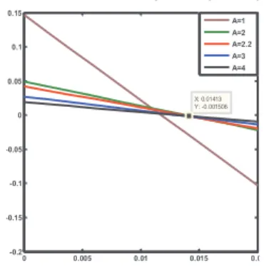
Figure 8: Wall friction variation τ as a function of Re/Gr for different values of aspect ratio A
The figure 8 shows the variation of τ versus Rey/Gr for different values of A. We notice that τ decreases linearly with Re / Gr for all values of A. The friction is even more important than the aspect ratio A is low. The maximum value is reached for A = 1, corresponding to a square channel. Beyond the value A = 2, the curves tend to merge, which shows that A = 2 is a limiting value. The intersection of these curves with the horizontal axis indicates the nullity of the friction coefficient. It is noted that this value is even greater than A is greater and it corresponds to the reversed flow. These figures
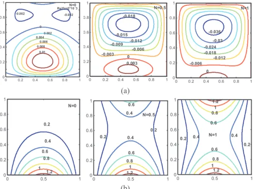
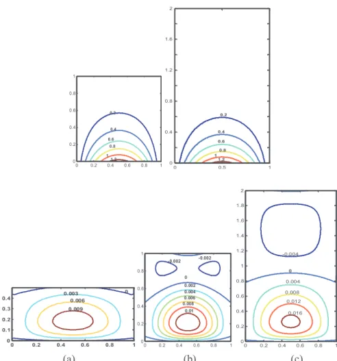
illustrate the contour of the velocity W2for A = 1 (square) as a function of N. It is found
that the line for N value close to zero is in the vicinity of the horizontal and vertical walls. Figure 9(a, b) shows the iso-values of velocity w and temperature θ. It is observed for the case 1 (N=0) that the reversed flow appears on the side of the cold wall and the velocity increases gradually as it approaches the hot wall Figure 9(b). When N increases, the velocity tends to have negative values.
0 0.005 0.01 0.015 0.02 -0.2 -0.15 -0.1 -0.05 0 0.05 0.1 0.15 X: 0.01413 Y: -0.001506 A=1 A=2 A=2.2 A=3 A=4
(a)
(b)
Figure 9: Contours lines of velocity (a) and temperature (b) for different values of N and for aspect ratio A=1
Figure 10: Contours lines of convection velocity for different values of N (and) for aspect ratio A=1
The Figure 10 is presented in the form of only one cell for the case N = 0, these values are positive. When N increases we get two cells, one of a positive strength and the other of a negative (one). The second cell spreads out increasingly as the number N increases. It should be noted that for N= 1 the two cells share the surface equally. In the limiting case A=2.2 the reverse flow is fully developed from N=0.5, in Figure 11 (a) For N = 1,
corresponding to T1= T2the isotherms show the appearance of a zone increasingly hot
on the side of the lower temperature wall this is represented in Figure 11(b).
Re/Gr=2*10-3 0 0.2 0.4 0.6 0.8 1 0 0.2 0.4 0.6 0.8 1 -0.002 -0.002 0.01 0.008 0.006 0.004 0.002 0 N=0 0 0.2 0.4 0.6 0.8 1 0 0.2 0.4 0.6 0.8 1 0.003 0 -0.018 -0.015 -0.003 -0.006 -0.009 -0.012 N=0.5 N=1 0 0.2 0.4 0.6 0.8 1 0 0.2 0.4 0.6 0.8 1 -0.006 -0.012 -0.036 -0.03 -0.024 -0.018 0 N=0 0 0.5 1 0 0.2 0.4 0.6 0.8 1 0.2 0.4 0.6 0.8 1 1.2 N=0.5 0 0.5 1 0 0.2 0.4 0.6 0.8 1 0.2 0.2 0.4 0.4 0.6 0.8 1 1.2 0.6 N=1 0 0.5 1 0 0.2 0.4 0.6 0.8 1 0.2 0.2 0.4 0.4 0.6 0.8 1 1.2 0.6 0.8 1 1.2 0 0.2 0.4 0.6 0.8 1 0 0.2 0.4 0.6 0.8 1 N=0 0.02 0.015 0.01 0.005 0 0.2 0.4 0.6 0.8 1 0 0.2 0.4 0.6 0.8 1 0 -0.002 0.016 0.014 0.012 0.01 0.008 0.006 0.004 0.002 N=0.5 N=1 -0.01 0 0.2 0.4 0.6 0.8 1 0 0.2 0.4 0.6 0.8 1 -0.005 0.005 0.01 0
(a)
(b)
Figure 11: Contours lines of (a) velocity and (b)temperature for different values of N and for aspect ratio A=2.2
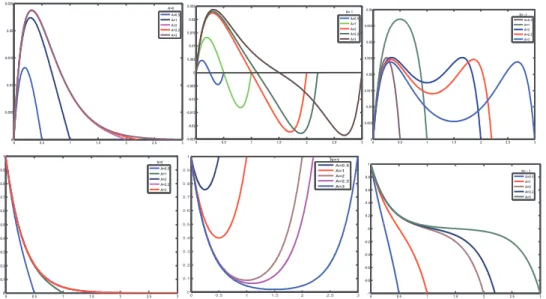
4.3 Velocity and temperature radial profiles
The influence of the aspect ratio A on the radial velocity and temperature profiles for different values of N is shown in Figure 12(a, b): For the velocity profile 12 (a), in the case N=0, the figure shows that the maximum increases with the aspect ratio. It is situated at the center of the cross section for low values of A. For N=1, the profile in Fig 13(a, b): is characterized by negative values of the velocity. These negative values indicate a reversal flow, induced by the buoyancy forces in the vicinity of the walls where the radial thermal gradient is positive. At the other wall the velocity presents a maxima, which increases with A. When, N=-1, for low values of A, the velocity radial profile reaches the Poiseuille profile. When A increases the profile presents a maxima near the walls and a minima at the center of the channel. With respect to the radial temperature profile (in) Figure (b), one notes that for N=0 the temperature decreases from its maximum value θ=1 at the hot wall to its minimum value θ=0 at the cold wall. However, when N=1, the temperature profile is symmetric about the channel centerline of the, and the minimum decreases as A increases. This aspect disappears for N=-1, where the two walls are maintained at opposed dimensionless temperatures values. One then finds (s) that the temperature curve has an inflection point which indicates the presence of a thermal instability.
N=0 0 0.5 1 0 0.5 1 1.5 2 0 0.001 0.002 0.003 0.004 -0.006 -0.005 -0.004 -0.003 -0.002 -0.001 N=0.5 0 0.5 1 0 0.5 1 1.5 2 0 -0.002 -0.004 -0.008 -0.0014 -0.016 -0.02 0.0020.004 0.006 0.008 0.01 0.012 -0.006 -0.01 -0.012 -0.0018 N=1 0 0.5 1 0 0.5 1 1.5 2 0 0.01 -0.002 -0.004 -0.006 -0.008 0.008 0.002 0.004 0.006 -0.02 -0.018 -0.016 -0.012 -0.01 N=0 0 0.5 1 0 0.5 1 1.5 2 0.00625 0.0125 0.01875 0.03125 N=0.5 0 0.5 1 0 0.5 1 1.5 2 0.0625 0.0625 0.075 0.075 0.05 0.05 0.0375 0.0375 0 0.5 1 0 0.5 1 1.5 2 0.03125 0.0625 0.09375 N=1 0.125 0.125 0.09375 0.03125 0.0625
Figure 12: Radial profile of convection velocity(a) and temperature (b) for different values of aspect ratio A
(a) (b) (c)
Figure 13: Contours lines of velocity for: Re/Gr=2*10 3
4.4 Comparison of thermal and dynamic contours at different aspect ratios (A = 0.5, 1, 2) for N = 0:
When the aspect ratio increases, the dynamic and thermal isolines in Figure 14(a,b,c) occupy more and more extended regions in the vicinity of the cold wall, this is due to the effect of the convection forces.
0 0.5 1 1.5 2 2.5 3 0 0.005 0.01 0.015 0.02 0.025 A=0.5 A=1 A=2 A=2.2 A=3 N=0 0 0.5 1 1.5 2 2.5 3 -0.025 -0.02 -0.015 -0.01 -0.005 0 0.005 0.01 0.015 0.02 0.025 N= 1 A=0.5 A=1 A=2 A=2.2 A=3 0 0.5 1 1.5 2 2.5 3 0 0.005 0.01 0.015 0.02 0.025 0.03 0.035 0.04 N= -1 A=0.5 A=1 A=2 A=2.2 A=3 0 0.5 1 1.5 2 2.5 3 0 0.1 0.2 0.3 0.4 0.5 0.6 0.7 0.8 0.9 1 A=0.5 A=1 A=2 A=2.2 A=3 N=0 0 0.5 1 1.5 2 2.5 3 0 0.1 0.2 0.3 0.4 0.5 0.6 0.7 0.8 0.9 1 A=0.5 A=1 A=2 A=2.2 A=3 N=1 0 0.5 1 1.5 2 2.5 3 -1 -0.8 -0.6 -0.4 -0.2 0 0.2 0.4 0.6 0.8 1 A=0.5 A=1 A=2 A=2.2 A=3 N= - 1 N=0 0 0.2 0.4 0.6 0.8 1 0 0.1 0.2 0.3 0.4 0.5 0.6 0.7 0.8 0.9 1 0.002 -0.002 -0.002 0.004 0.006 0.008 0.01 0 N=1 0 0.2 0.4 0.6 0.8 1 0 0.1 0.2 0.3 0.4 0.5 0.6 0.7 0.8 0.9 1 -0.03 -0.02 -0.01 0 N= -1 0 0.2 0.4 0.6 0.8 1 0 0.2 0.4 0.6 0.8 1 0.04 0.03 0.02 0.01
(a) (b) (c)
Figure 14: Contours lines of temperature and velocity for N=0 and for aspect ratio (a)A=0.5, (b)A=1, and (c) A=2
0 2 4 6 8 10 12 14 0,0 0,5 1,0 1,5 2,0 2,5 3,0 3,5 4,0 Pr旛ente旜ude C.H. Ching et al A = Y0 /Z0 Re/Gr . 103
Figure 15: Stability curve of flow
0 0.2 0.4 0.6 0.8 1 0 0.2 0.4 0.6 0.8 1 0.2 0.4 0.6 0.8 1 1.2 0 0.5 1 0 0.4 0.8 1.2 1.6 2 0.2 0.4 0.6 0.8 1 1.2 0 0.2 0.4 0.6 0.8 1 0 0.1 0.2 0.3 0.4 0.009 0.006 0.003 0 0 0.2 0.4 0.6 0.8 1 0 0.2 0.4 0.6 0.8 1 -0.002 -0.002 0.008 0.01 0.006 0.004 0.002 0 0 0.2 0.4 0.6 0.8 1 0 0.2 0.4 0.6 0.8 1 1.2 1.4 1.6 1.8 2 0.016 0.012 0.008 0.004 0 -0.004
4.5 Flow stability curve
The reversed flow present in some cases of temperature boundary conditions and of Re / Gr values is strongly dependent on the aspect ratio A. Indeed, the results show that this dependence is very strong for certain values below critical one 2.22. Beyond this value the flow is completely stable. The stability curve is determined by zero friction at the wall. These results are in very good agreement with those found by Cheng and Weng (1991).
5 Conclusion
A laminar ascending flow in a vertical channel formed by two wet parallel flat plates with a thin film of water is studied analytically and numerically for different conditions of temperature and concentration, as well as different values of the aspect ratio. The analytical study concerned only the thermal case whereas the numerical solution has considered the double diffusion.
The results obtained by the two methods are compared with each other and are checked against those of other authors for similar cases. A good agreement is found in particular for the streamlines, the local coefficients of heat and mass transfer as well as for the average Nusselt, Sherwood numbers and the criteria for the stability of the flow. The analytical study has shown that the reversed flow is present for some cases of wall temperature conditions and for certain values of the ratio, Re/Gr. It is also strongly dependent on the aspect ratio A. Indeed, the results show that this dependence is very strong for values less 2.22. The stability curve has been determined from the friction forces at the wall τ for different values of the aspect ratio A.
In the case A=2.2 the reversed flow is developed completely from the value N=0.5. It is noted that the wall shear decreases linearly with Re / Gr for all values of A, and the friction along the wall is all the more important than the aspect ratio A is low.
The numerical results show: that in the absence of mass transfer, the evaporation rate remains null along the channel. The velocity decreases along the pipe in case of a favorable mass gradient to cancel at position x=15. It increases in the case of an unfavorable mass gradient to cancel at position x=20 and merges with the curve representing the forced convection. It should be noted that there is a slight difference between the two curves in the immediate vicinity of the inlet region where it is found that the axial gradient of the rate of evaporation is larger in the case of the heat and mass transfer compared to the case of forced convection.
In the absence of heat transfer, curves indicate that the values of evaporation rate are less important than in the case of the double diffusion and they are of the order of its half.
References
AitHammou, Z.; Benhamou, B.; Galanis, N.; Orfi, J. (2003): Laminar mixed convection of humid air in a vertical channel with evaporation or condensation at the wall. International Journal of thermal Sciences, vol. 43, pp.531-539.
Agunaoun, A.; Idrissi, A. Il.; DaÏf, A. ; Barriol, R. (1998): Study of evaporation in mixed convection of a liquid film of binary mixture flowing on an inclined plane subjected to a constant heat flux . International Journal of Heat and Mass transfer, vol. 41, pp. 2197-2210.
Belhadj Mohamed, A.; Orfi, J.; Debissi, C.; Ben Nasrallah, S. (2007): Heat and mass transfer during condensation in a vertical channel under mixed convection. Heat Mass Transfer, vol. 43, pp.851-861
Chin-Hsiang, C.; Chun-Jen, W. (1991): Flow reversal of combined convection in a vertical Rectangular duct with unequally isothermal walls. International Communications is Heat Mass Transfer, vol. 18, pp.127-140.
Cherif, A. S.; Kassim, M. A.; Benhamou, B. et al. (2011): Experimental and numerical study of mixed convection heat and mass transfer in a vertical channel with film evaporation. International Journal of Thermal Sciences, vol.50, pp.942-953.
Chien-Chang, H.; Wei-Mon, Y.; Jer-Huan, J. (2005): Laminar mixed convection heat and mass transfer in vertical rectangular ducts with film evaporation and condensation. International Journal Heat and Mass transfer, vol. 48, pp. 1772-1784.
KiariGoni, B.; Galanis, N.; Orfi, J. (2012): Thermosolutal mixed convection and flow-reversal in an inclined parallel-plate channel. Heat Mass Transfer, vol. 48, pp.1601-1613. Lefi, N.; Boukadida, N. (2008): transfert couplé de chaleur et de masse lors de l’évaporation des liquides en régime instationnaire. Revue des Energies Renouvelables, pp.217-225.
Nasr, A.; Debbissi, C.; Ben Nasrallah, S. (2010): Evaporation of a Thin Binary Liquid Film by Forced Convection into Air and Superheated Steam. Journal of Thermal Science, vol.19, no.4, pp. 346-356.
Nait Alla, A.; Feddaoui, M.; Meftah, H. (2015): Numerical study of the evaporation by mixed convection of ethanol in partially heated plate along a vertical channel. International Journal Heat and Mass transfer, vol. 89, pp. 206-215.
Oulaid, O.; Benhamou, B.; Galanis, N. (2010): Flow reversal in combined laminar mixed convection heat and mass transfer with phase change in a vertical channel. International Journal Heat and Fluid Flow, vol. 31, pp. 711-721.
Podvin, B.; Le Quéré, P. (2013): Nonlinear dynamics between two differentially heated vertical plates in the presence of stratification. Theoretical Computational Fluid Dynamics, vol. 27, pp. 89-114.
Senhaji, S.; Feddaoui, M.; Mediouni, T.; Mir, A. (2009): Simultaneous heat mass transfer inside a vertical tube in evaporating a heated falling alcohols liquid film into a stream of dry air. Heat Mass Transfer, vol.45, pp. 663-671
Sergent, A. ; Gao,Z. ; Podvin,B. ; Xin,S. ; Le Quéré, P. (2011): Simulation de l’´ecoulement dans un canal differentiellement chauffé. 20 ème Congrès Français de Mécanique Besançon, 29 Aout au 2 septembre
Shah, R. K.; London, A. L. (1978) Laminar flow forced convection in Ducts. Academic Press, New York.
Terzi, A.; Ben Jabrallah, S.; Harmand, S. (2016): Experimental Study of Heat and Mass Transfer for Liquid Film Evaporation along a Vertical Plate Covered with a Porous Layer. Journal of Applied Fluid Mechanics, vol. 9, pp.113-120
![Figure 3: Comparison between our (the authors) results and those of [Oulaid, Benhamou and Galais (2010)] for the transverse vapour velocity for different Grashof numbers yx00.2 0.40510152025 yx00.2 0.40510152025 yx00.2 0.4051015202505101](https://thumb-eu.123doks.com/thumbv2/123doknet/14325626.497754/13.892.180.739.218.460/figure-comparison-authors-benhamou-transverse-velocity-different-grashof.webp)