HAL Id: hal-00664531
https://hal.archives-ouvertes.fr/hal-00664531
Submitted on 30 Jan 2012
HAL is a multi-disciplinary open access
archive for the deposit and dissemination of
sci-entific research documents, whether they are
pub-lished or not. The documents may come from
teaching and research institutions in France or
abroad, or from public or private research centers.
L’archive ouverte pluridisciplinaire HAL, est
destinée au dépôt et à la diffusion de documents
scientifiques de niveau recherche, publiés ou non,
émanant des établissements d’enseignement et de
recherche français ou étrangers, des laboratoires
publics ou privés.
Quantitative MRFM characterization of the autonomous
and forced dynamics in a spin transfer nano-oscillator
A. Hamadeh, G. de Loubens, V. V. Naletov, J. Grollier, Ch. Ulysse, V. Cros,
O. Klein
To cite this version:
A. Hamadeh, G. de Loubens, V. V. Naletov, J. Grollier, Ch. Ulysse, et al.. Quantitative MRFM
characterization of the autonomous and forced dynamics in a spin transfer nano-oscillator. Physical
Review B: Condensed Matter and Materials Physics (1998-2015), American Physical Society, 2012,
85, pp.140408. �10.1103/PhysRevB.85.140408�. �hal-00664531�
in a spin transfer nano-oscillator
A. Hamadeh,1 G. de Loubens,1, ∗ V.V. Naletov,1, 2 J. Grollier,3 C. Ulysse,4 V. Cros,3 and O. Klein1,†
1
Service de Physique de l’ ´Etat Condens´e (CNRS URA 2464), CEA Saclay, 91191 Gif-sur-Yvette, France
2
Physics Department, Kazan Federal University, Kazan 420008, Russian Federation
3
Unit´e Mixte de Physique CNRS/Thales and Universit´e Paris Sud 11, RD 128, 91767 Palaiseau, France
4
Laboratoire de Photonique et de Nanostructures, Route de Nozay 91460 Marcoussis, France (Dated: January 30, 2012)
Using a magnetic resonance force microscope (MRFM), the power emitted by a spin transfer nano-oscillator consisting of a normally magnetized Py∣Cu∣Py circular nanopillar is measured both in the autonomous and forced regimes. From the power behavior in the subcritical region of the autonomous dynamics, one obtains a quantitative measurement of the threshold current and of the noise level. Their field dependence directly yields both the spin torque efficiency acting on the thin layer and the nature of the mode which first auto-oscillates: the lowest energy, spatially most uniform spin-wave mode. From the MRFM behavior in the forced dynamics, it is then demonstrated that in order to phase-lock this auto-oscillating mode, the external source must have the same spatial symmetry as the mode profile, i.e., a uniform microwave field must be used rather than a microwave current flowing through the nanopillar.
Recent progress in spin electronics have demonstrated that owing to the spin transfer torque (STT) [1, 2], bi-asing magnetic hybrid nanostructures by a direct cur-rent can lead to microwave emission. These spin transfer nano-oscillators (STNOs) [3–5] offer decisive advantages compared to existing technology in tunability, agility, compactness and integrability. In view of their applica-tions in high-frequency technologies, a promising strat-egy to improve the coherence and increase the emitted microwave power of these devices is to mutually synchro-nize several of them [6–10].
The synchronization of the STNO oscillations to an ex-ternal source has already been demonstrated [11, 12]. In particular, it has been shown that symmetric perturba-tions to the STNO trajectory favor even synchronization indices (ratio of the external frequency to the STNO fre-quency r = 2, 4, 6...), while antisymmetric perturbations favor odd synchronization indices [13, 14]. But so far, the influence of the spatial symmetry of the spin-wave (SW) mode which auto-oscillates on the synchronization rules has not been elucidated.
To address this open question, the spectroscopic iden-tification of the auto-oscillating mode is crucial. It is usually a challenge, as a large variety of dynamic modes can be excited in STNOs, and their nature can change de-pending on the geometry, magnetic parameters and bias conditions. In this work, we study a STNO in the most simple configuration: a circular nanopillar saturated by a strong magnetic field applied along its normal. It corre-sponds to an optimum configuration for synchronization, since it has a maximal nonlinear frequency shift, which provides a large ability for the STNO to lock its phase to an external source [8]. Moreover, the perpendicular con-figuration coincides with the universal oscillator model, for which an exact analytical theory can be derived [15]. Last but not least, this highly symmetric case allows for
a simplified classification of the SW eigenmodes inside the STNO [16].
We shall use here a magnetic resonance force micro-scope (MRFM) to monitor directly the power emitted by this archetype STNO vs. the bias dc current and perpen-dicular magnetic field. In the autonomous regime, these quantitative measurements allow us to demonstrate that the mode which auto-oscillates just above the threshold current is the fundamental, spatially most uniform SW mode. By studying the forced regime, we then show that this mode synchronizes only to an external source sharing the same spatial symmetry, namely, a uniform microwave magnetic field, and not the common microwave current passing through the device.
For this study, we use a circular nanopillar of nom-inal diameter 200 nm patterned from a (Cu60∣PyB15∣ Cu10∣PyA4∣Au25) stack, where thicknesses are in nm and Py=Ni80Fe20. A dc current Idc and a microwave cur-rent irf can be injected through the STNO using the bottom Cu and top Au electrodes. A positive current corresponds to electrons flowing from the thick PyB to the thin PyA layer. This STNO device is insulated and an external antenna is patterned on top to generate a spatially uniform microwave magnetic field hrf oriented in the plane of the magnetic layers. The bias magnetic field Hext, ranging between 8.5 and 11 kOe, is applied at θH= 0○from the normal to the sample plane.
The room temperature MRFM setup [17] consists of a spherical magnetic probe attached at the end of a very soft cantilever, coupled dipolarly to the buried nanopillar (see inset of Fig.1) and positioned 1.5 µm above its cen-ter. This mechanical detection scheme [18, 19] sensitively measures the variation of the longitudinal magnetization ∆Mz over the whole volume of the magnetic body [20], a quantity directly proportional to the normalized power
2
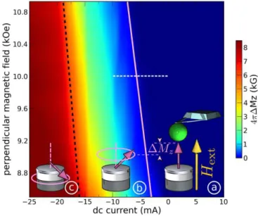
FIG. 1. (Color online). Phase diagram of the STNO au-tonomous dynamics measured by MRFM.
pemitted by the STNO [15]:
p=∆Mz 2Ms
, (1)
where Msis the saturation magnetization of the precess-ing layer.
First, we measure the phase diagram of the STNO au-tonomous dynamics as a function of Idc and Hext, see Fig.1. In this experiment, Idc is fully modulated at the cantilever frequency, fc ≈ 12 kHz, and the mechanical signal represents ∆Mz synchronous with the injection of Idc through the STNO. This quantitative measurement [21] is displayed using the color scale indicated on the right of Fig.1.
Three different regions can be distinguished in this phase diagram. At low negative or positive current (re-gion a○), ∆Mz is negligible, because in the subcritical region, the STT is not sufficient to destabilize the mag-netization in the thin or thick layer away from the per-pendicular applied field direction. As Idc is reaching a threshold negative value (from −3 to −7 mA as Hext in-creases from 8.5 to 10.7 kOe, see pink solid line in Fig.1), the MRFM signal starts to smoothly increase in region
b
○. It corresponds to the onset of spin transfer driven oscillations in the thin layer, which will be analyzed in details below. As Idc is further decreased towards more negative values, the angle of precession increases in the thin layer, until it eventually reaches 90°: at the bound-ary between regions b○ and c○ (see black dashed line) 4π∆Mz equals the full saturation magnetization in the thin layer, 4πMs= 8 kG.
Let us now concentrate on the spin transfer dynamics in the thin layer at Idc< 0. We first turn to the quanti-tative analysis of the subcritical region a○. We introduce
N = V Ms/(gµB), the number of spins in the thin layer (V is its volume, g the Land´e factor, µBthe Bohr magne-ton). The averaged normalized power p in the subcritical regime (∣Idc∣ < Ith) is evaluated in the stochastic nonlin-ear oscillator model described in section VII of ref. [15]. Under the assumption that only one SW mode dominates the STNO autonomous dynamics, Eq.(1) follows the sim-ple relationship: ∆Mz 2Ms = kBT N ̵hων 1 1 − Idc/Ith, (2) where Ith = 2αωνN e/ǫ is the threshold current for auto-oscillation of the SW mode ν with frequency ων(α is the Gilbert damping constant in the thin layer, e the electron charge, and ǫ the spin torque efficiency). In Eq.(2), the prefactor
η≡ kBT
N ̵hων (3)
is the noise power: the ratio between the thermal energy (kB is the Boltzmann constant, T the temperature) and the maximal energy stored in the SW mode ν (̵h is the Planck constant over 2π).
From Eq.(2), the inverse power is linear with the bias current Idc in the subcritical region. A sample measure-ment at Hext = 10 kOe (along the white dashed line in Fig.1) is shown in Fig.2a. From a linear fit, one can thus obtain the threshold current Ith and the noise power η at this particular field. The dependencies of Ith and η on the perpendicular magnetic field are plotted in Figs.2b and 2c, respectively.
The parameters V , Ms, g (hence, N ≃ 6.3 × 10⁶) and α= 0.014 of the thin layer have been determined from an extensive MRFM spectroscopic study performed at Idc= 0 on the same sample and published in ref.[16]. This study also yields the dispersion relations ων = γ(Hext− Hν) of the thin layer SW modes (γ = gµB/̵h = 1.87 × 10⁷ rad.s−1.G−1 is the gyromagnetic ratio, Hν the so-called Kittel field associated to the mode ν). By injecting ων in the expression of the threshold current, it is found that the latter depends linearly on the perpendicular bias field:
Ith= 2αN e
ǫ γ(Hext− Hν) , (4) as observed in Fig.2b. The linear fit of Ithvs. Hextusing Eq.(4) yields Hν = 6.80 ± 0.15 kOe and ǫ = 0.30 ± 0.005. The importance of the analysis of Fig.2b is that, first, it provides an accurate determination of the spin torque efficiency, found to be in agreement with the accepted value in similar STNO stacks [22]. Second, a comparison with the SW modes of the thin layer (see black symbols extracted from ref.[16] and mode profiles in Fig.2b) shows that the fitted value of Hν precisely corresponds to the Kittel field of the (ℓ, n) = (0, 0) mode, ℓ and n being re-spectively the azimuthal and radial mode indices. It thus
FIG. 2. (Color online). (a) Determination of the threshold current Ith and noise power η at Hext= 10 kOe, from the inverse
MRFM signal in the subcritical regime. Dependencies of the threshold current (b) and noise power (c) on the perpendicular magnetic field.
allows us to conclude about the nature of the mode that first auto-oscillates at Idc< 0 as being the fundamental, most uniform precession mode of the thin layer.
To gain further insight in our analysis of the subcritical regime, we compare in Fig.2c the noise power determined as a function of Hext with the prediction of Eq.(3), in which the dispersion relation of the ν = (0, 0) SW mode is used. It is found that the fluctuations of the STNO power are well accounted for by those of the previously identified auto-oscillating mode, which confirms that the single mode assumption made to derive Eq.(2) is a good approximation.
Using two different microwave circuits, we shall now compare the ability of the auto-oscillating SW mode to phase-lock either to the uniform microwave field hrf gen-erated by the external antenna, or to the microwave current irf flowing through the nanopillar. We know from previous studies that in the exact perpendicular configuration, the SW spectrum critically depends on the method of excitation [16]: hrf excites only the ax-ially symmetric modes having azimuthal index ℓ = 0, whereas due to the orthoradial symmetry of the induced microwave Oersted field, irf excites only the modes hav-ing azimuthal index ℓ = +1. The dependencies on Idc and Hext of the STNO dynamics forced respectively by hrf and irf are presented in Figs.3a and 3b. The plot-ted quantity is ∆Mz synchronous with the full modula-tion of the external source power: hrf = 1.9 Oe (a) and irf = 140 µA (b). Although the ℓ = 0 and ℓ = +1 spectra are in principle shifted by 1.1 GHz from each other, a direct comparison of the phase diagrams (a) and (b) can be made by using different excitation frequencies for hrf (8.1 GHz) and irf (9.2 GHz).
Below the threshold current (indicated by the pink lines in Fig.3), the observed behaviors of the ℓ = 0 and ℓ = +1 modes are alike: a small negative dc current slightly attenuates the SW modes Bℓn of the thick PyB layer, while it promotes quite rapidly the SW modes Aℓn
FIG. 3. (Color online). MRFM measurement of the STNO dynamics forced by (a) the uniform field hrf at 8.1 GHz and
(b) the orthoradial Oersted field produced by irfat 9.2 GHz,
as a function of Idc and Hext. The black traces show the
MRFM signal vs. Idc at Hext = 8.8 kOe. The pink solid
lines show the location of the threshold current determined in Fig.2b. The dashed lines are guides to the eye.
of the thin PyA layer, in agreement with the expected symmetry of the STT [16]. On the contrary, there is a clear qualitative difference between the modes A00 and A10 beyond Ith. Although both peaks similarly shift to-wards lower field as Idc is decreased towards lower nega-tive values, A00 gets strongly distorted, with the appear-ance of a negative dip on its high field side, in contrast to A10, which remains a positive peak.
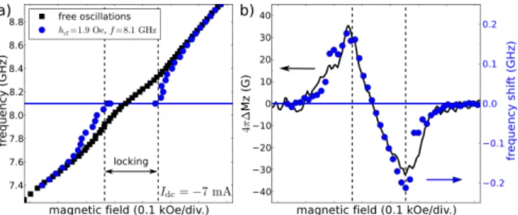
The negative MRFM signal observed in Fig.3a in the region of spin transfer driven oscillations in the thin layer is striking, because it means that the precession angle can be reduced in the presence of the microwave exci-tation hrf. As a matter of fact, the distortion of the peak A00is associated to the synchronization of the auto-oscillating mode to the external signal. Fig.4a illustrates the distortion of the STNO emission frequency induced by this phenomenon. These data were obtained by mon-itoring the fluctuating voltage across the nanopillar at Idc = −7 mA with a spectrum analyzer as a function of
4
FIG. 4. (Color online). (a) Magnetic field dependence of the STNO frequency in the free and forced regimes (the external source at 8.1 GHz is hrf). (b) Comparison between the STNO
frequency shift deduced from (a) and the MRFM signal.
the applied magnetic field [23]. The frequency shift of the forced oscillations with respect to the free running oscillations is plotted in Fig.4b, along with the MRFM signal. This demonstrates that in the so-called phase-locking range, the STNO amplitude adapts (∆Mz > 0: increases, ∆Mz< 0: decreases), so as to maintain its fre-quency equal to the frefre-quency of the source, here fixed at 8.1 GHz. This comparison also allows to estimate the phase-locking bandwidth, found to be as large as 0.4 GHz despite the small amplitude of the external sig-nal. The nonlinear frequency shift is indeed the largest in the perpendicular configuration, N = 4γMs≃ 48 GHz [15], therefore, a small change of the power emitted by the STNO is sufficient to change its frequency by a sub-stantial amount.
Such a signature of synchronization of the auto-oscillating mode is not observed in Fig.3b, where the ex-ternal source is the microwave current. This highlights the crucial importance of the symmetry associated to the SW mode driven by STT: in the exact perpendicular con-figuration, irf can only excite ℓ = +1 SW modes, there-fore, it has the wrong symmetry to couple to the auto-oscillating mode, which was shown in Fig.2 to bare the azimuthal index ℓ = 0. We add that in our exact axially symmetrical case, no phase-locking behavior is observed with the even synchronization index r = 2, neither with irf, nor with hrf, which is due to the perfectly circular STNO trajectory.
To conclude, based on the quantitative analysis of both the critical current and the noise power in the subcriti-cal regime, we have unambiguously identified the auto-oscillating mode in the perpendicular configuration of a nanopillar. This case is particularly interesting due to its large ability to synchronize to an external source. But we have shown that in addition to the symmetry of the perturbation with respect to the STNO trajectory [14], the overlap integral between the external source and the auto-oscillating mode profile is crucial to synchroniza-tion rules. Due to symmetry reasons, only the uniform microwave field applied perpendicularly to the bias field and with the synchronization index r = 1 is efficient to
phase-lock the STNO dynamics in the present work. We believe that this finding might be important for future strategies to synchronize large STNOs arrays.
We thank A. N. Slavin for useful discussions and his support. This research was supported by the European Grant Master (NMP-FP7 212257) and by the French Grant Voice (ANR-09-NANO-006-01).
∗ Corresponding author: [email protected] †
Co-author: [email protected]
[1] J. Slonczewski, J. Magn. Magn. Mater. 159, L1 (1996). [2] L. Berger, Phys. Rev. B 54, 9353 (1996).
[3] S. I. Kiselev, J. C. Sankey, I. N. Krivorotov, N. C. Em-ley, R. J. Schoelkopf, R. A. Buhrman, and D. C. Ralph, Nature 425, 380 (2003).
[4] W. H. Rippard, M. R. Pufall, S. Kaka, S. E. Russek, and T. J. Silva, Phys. Rev. Lett. 92, 027201 (2004).
[5] D. Houssameddine, U. Ebels, B. Delat, B. Rodmacq, I. Firastrau, F. Ponthenier, M. Brunet, C. Thirion, J.-P. Michel, L. Prejbeanu-Buda, M.-C. Cyrille, O. Redon, and B. Dieny, Nature Mater. 6, 447 (2007).
[6] S. Kaka, M. R. Pufall, W. H. Rippard, T. J. Silva, S. E. Russek, and J. A. Katine, Nature 437, 389 (2005). [7] F. B. Mancoff, N. D. Rizzo, B. N. Engel, and S. Tehrani,
Nature 437, 393 (2005).
[8] A. N. Slavin and V. S. Tiberkevich, Phys. Rev. B 72, 092407 (2005).
[9] J. Grollier, V. Cros, and A. Fert, Phys. Rev. B 73, 060409 (2006).
[10] A. Ruotolo, V. Cros, B. Georges, A. Dussaux, J. Grollier, C. Deranlot, R. Guillemet, K. Bouzehouane, S. Fusil, and A. Fert, Nature Nanotech. 4, 528 (2009).
[11] W. H. Rippard, M. R. Pufall, S. Kaka, T. J. Silva, S. E. Russek, and J. A. Katine, Phys. Rev. Lett. 95, 067203 (2005).
[12] B. Georges, J. Grollier, M. Darques, V. Cros, C. Deran-lot, B. Marcilhac, G. Faini, and A. Fert, Phys. Rev. Lett. 101, 017201 (2008).
[13] M. Quinsat, J. F. Sierra, I. Firastrau, V. Tiberke-vich, A. Slavin, D. Gusakova, L. D. Buda-Prejbeanu, M. Zarudniev, J.-P. Michel, U. Ebels, B. Dieny, M.-C. Cyrille, J. A. Katine, D. Mauri, and A. Zeltser, Appl. Phys. Lett. 98, 182503 (2011).
[14] S. Urazhdin, P. Tabor, V. Tiberkevich, and A. Slavin, Phys. Rev. Lett. 105, 104101 (2010).
[15] A. Slavin and V. Tiberkevich, IEEE Trans. Magn. 45, 1875 (2009).
[16] V. V. Naletov, G. de Loubens, G. Albuquerque, S. Bor-lenghi, V. Cros, G. Faini, J. Grollier, H. Hurdequint, N. Locatelli, B. Pigeau, A. N. Slavin, V. S. Tiberke-vich, C. Ulysse, T. Valet, and O. Klein, Phys. Rev. B 84, 224423 (2011).
[17] O. Klein, G. de Loubens, V. V. Naletov, F. Boust, T. Guillet, H. Hurdequint, A. Leksikov, A. N. Slavin, V. S. Tiberkevich, and N. Vukadinovic, Phys. Rev. B 78, 144410 (2008).
[18] G. de Loubens, V. V. Naletov, O. Klein, J. Ben Youssef, F. Boust, and N. Vukadinovic, Phys. Rev. Lett. 98, 127601 (2007).
[19] B. Pigeau, G. de Loubens, O. Klein, A. Riegler, F. Lochner, G. Schmidt, and L. W. Molenkamp, Nature Phys. 7, 26 (2011).
[20] G. de Loubens, V. V. Naletov, and O. Klein, Phys. Rev. B 71, 180411 (2005).
[21] V. V. Naletov, V. Charbois, O. Klein, and C. Fermon,
Appl. Phys. Lett. 83, 3132 (2003).
[22] V. S. Rychkov, S. Borlenghi, H. Jaffres, A. Fert, and X. Waintal, Phys. Rev. Lett. 103, 066602 (2009). [23] Here, a slight tilt of the angle θH= 2○is required. Indeed,
no oscillatory voltage is produced in the exact perpendic-ular configuration, due to the perfect axial symmetry of the STNO trajectory.