HAL Id: inria-00491795
https://hal.inria.fr/inria-00491795v2
Submitted on 18 Jun 2010
HAL is a multi-disciplinary open access
archive for the deposit and dissemination of
sci-entific research documents, whether they are
pub-lished or not. The documents may come from
teaching and research institutions in France or
abroad, or from public or private research centers.
L’archive ouverte pluridisciplinaire HAL, est
destinée au dépôt et à la diffusion de documents
scientifiques de niveau recherche, publiés ou non,
émanant des établissements d’enseignement et de
recherche français ou étrangers, des laboratoires
publics ou privés.
DHT-based distributed ALE engine in RFID
Middleware
Loïc Schmidt, Roudy Dagher, Roberto Quilez, Nathalie Mitton, David
Simplot-Ryl
To cite this version:
Loïc Schmidt, Roudy Dagher, Roberto Quilez, Nathalie Mitton, David Simplot-Ryl. DHT-based
distributed ALE engine in RFID Middleware. [Research Report] RR-7316, INRIA. 2010, pp.22.
�inria-00491795v2�
a p p o r t
d e r e c h e r c h e
0 2 4 9 -6 3 9 9 IS R N IN R IA /R R --7 3 1 6 --F R + E N GDHT-based distributed ALE engine in RFID
Middleware
Loïc Schmidt — Roudy Dagher — Roberto Quilez —
Nathalie Mitton — David Simplot-Ryl
N° 7316
Centre de recherche INRIA Lille – Nord Europe Parc Scientifique de la Haute Borne
Loïc Schmidt
∗, Roudy Dagher
∗, Roberto Quilez
∗,
Nathalie Mitton
∗, David Simplot-Ryl
∗Thème : Systèmes et services distribués Équipe-Projet POPS
Rapport de recherche n° 7316 — June 2010 — 19 pages
Abstract: Following the “Internet of Things” concept, each object is associated with a unique identifier which will allow to retrieve information about it in large databases.
In the process of managing a large amount of objects, and consequently a large amount of events from readers, without overloading the network, these events have to be filtered and aggregated. This is the aim of the Application Level Events (ALE) standard from EPCGlobal, which receives events from read-ers and sends a useful and well constructed report to the business application. The ALE may be connected to several hundreds of readers. As the number of readers may increase with the increase of the company, a bottleneck may appear with all readers events sent to the ALE. A solution for scalability is to distribute the ALE.
In this research report, we propose an efficient way to solve this problem based on a Distributed Hash table (DHT). One role of the ALE is to insu-late business application from technical concern so in our solution, we present a mechanism to distribute the ALE using Chord, a well-known peer-to-peer lookup system, and being transparent for business application. This solution is compliant with the EPCglobal existing standard, scalable, robust and transpar-ent for other layers of the middleware. We show that the overhead generated by our solution is of 10% only in a nominal case.
Key-words: Distributed ALE, EPC Global standards, RFID systems
This work is partly supported by FP7 Aspire European Project [22], the french project ICOM from the PICOM [23] (Pôle de compétitivité des Industries du COMmerce) and the French ANR project WINGS [24].
Machine à évènement distribuée pour les
middleware RFID
Résumé : Selon le concept de l’ “Internet des Objets”, à chaque objet est associé un identifiant unique permettant de retrouver des informations le concernant dans des grandes bases de données
Afin de pouvoir gérer un grand nombre d’objets, et par conséquent un grand nombre d’évènements venant des lecteurs, sans surcharger le réseau, ces évène-ments doivent être filtrés et aggrégés. C’est le rôle du standard de l’Application Level Events (ALE) de EPCGlobal, qui recoit les évènements des lecteurs et envoie un rapport bien construit aux applications métiers. Cette ALE peut être connectée à plusieurs centaines de lecteurs. Comme le nombre de lecteurs peut augmenter avec la taille de l’entreprise, un goulot d’étranglement peut appa-raitre avec tous les évènements des lecteurs recus par l’ALE. Distribuer l’ALE est une solution offrant le passage à l’échelle.
Dans ce rapport de recherche, nous proposons un moyen efficace de résoudre ce problème en se basant sur les tables de hachage distribuées (DHT). Un des rôles de l’ALE est d’isoler les applications métiers des parties techniques, notre solution propose un méchanisme pour distribuer l’ALE en utilisant Chord, un protocole pair-à-pair, tout en conservant cette transparence pour les applications métiers. Cette solution est compatible avec le standard existant d’EPCGlobal, passe à l’échelle, est robuste et est transparente pour les autres couche du mid-dleware. Nous montrons que le surcoût généré par notre solution est de 10% dans un cas nominal.
Contents
1 Introduction 4
2 Context 5
2.1 EPCGlobal Network . . . 5 2.2 Problem statement . . . 7 3 DHT and lookup in P2P systems 9 3.1 Preliminaries . . . 9 3.2 Related works . . . 10 4 DHT-based distributed ALE 11 4.1 P2P system . . . 11 4.2 Runtime mechanisms . . . 13
5 Results 15
4 Schmidt, Dagher, Quilez, Mitton & Simplot-Ryl
1
Introduction
The “Internet of Things” aims at creating a large wireless network in which all objects would have a unique identifier. This concept is attributed to the MIT Auto-ID Center, founded in 1999 [1].
This idea goes along with Radio Frequency IDentification technology (RFID). An RFID tag can be placed on all objects, offering a way to question them and know their identity. Using this ID, together with an efficient object name service (ONS) and shared databases, we retrieve information at anytime. The Auto-ID Center defines, with partners, several standards for the Internet of things. These standards can be found under the name of EPCglobal Network [2]. The Auto-ID Center is now known under the name of Auto-ID Labs. Once each item has its unique ID, called Electronic Product Code (EPC) in the EPCGlobal network, several operations can be performed (i.e. traceability, inventory, etc.).
The development of these standards provides a middleware offering a unified way to connect business applications to it and to perform the operations above-mentioned regardless of the technical concern (i.e. readers management, filtering and aggregation of reader events, etc.). In the case of an inventory operation, the middleware has to deal with several reader events to filter and aggregate in a single report for the business application that needs this inventory. One key aspect is to be compliant with these existing EPCglobal standards [3][4] because they are used in various companies all around the world. As EPCglobal is also a part of GS1 [6], which has standardized bar-codes such as EAN/UPC, these standards are already widespread in Europe and United States.
In this paper, our concern is a company with several warehouses equipped with RFID readers. The actual EPCGlobal ALE standard offers to business applications a way to make a stocklist of all products of all its warehouses by sending a specification to each ALE in each warehouse. All ALE engines will then send a report and the business application can eventually draw its inventory. In this paper, we propose a mechanism based on distributed hash tables and peer-to-peer (p2p) mechanisms that offer the same scalability to the ALE engine but in a transparent manner for business applications. An ALE, which is translated as a node of the p2p system, receiving specification has to split and distribute it to other involved ALEs and merge all reports locally before sending the final report to the business application. By doing so, our proposition is standard compliant, scalable, robust and transparent for other layers of the middleware. We will compute the overhead generated by our solution, that provides scalability.
This paper is organized as follows. In section 2 we give an overview of the electronic product code structure and EPC Global middleware. We also present the motivation and define the problem we are interested in. The following sec-tion (Secsec-tion 3) reviews the different solusec-tions found in the literature on the distribution of the ALE and on the DHT and lookup mechanisms. We then, in Section 4 present our solution before showing some results in Section 5. We compare execution time of a common specification without and with our distri-bution mechanisms, with and without distributed readers. We finally conclude in section 6.
2
Context
2.1
EPCGlobal Network
An Electronic Product Code (EPC) is an identifier used in the EPCglobal ar-chitecture [5]. Defined by several partners, such as the Auto-ID Labs, GS1, ETH Zurich, etc., it provides a way to uniquely identify items. The structure of an EPC is important in order to understand how it is unique. Based on the GS1 identification system used in EAN/UPC bar codes [6], the EPCGlobal Tag Data Standard [7][8] defines various kinds of EPC (such as SGTIN, SSCC, SGLN, GID, etc.) that have their own usage (e.g. SGTIN for trade items, SSCC for pallets, SGLN for localization, etc.).
The SGTIN (Serialized Global Trade Number) is a GS1 GTIN plus a serial number and is composed of six fields (Figure 1).
Header Filter Partition Company Item Serial Value Prefix Reference Number 8 bits 3 bits 3 bits 20-40 bits 24-4 bits 38 bits
Figure 1: Structure of the SGTIN
• Header: identify the kind of EPC we are dealing with (SGTIN, DoD, SSCC, etc.);
• Filter: indicate additional data used for fast-filtering;
• Partition: indicate the length of the Company Prefix and Item Reference; • Company Prefix: identify the product manufacturer (prefix given by GS1); • Item Reference: identify the class of item;
• Serial Number: identify the item itself.
The Company Prefix plus the Item Reference compose the GS1 GTIN. The Serial Number identifies uniquely the item from other items of the same class (i.e. with the same GTIN).
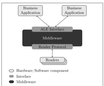
In addition of the EPC TDS [7], several standards have been developed by EPCGlobal in order to provide a general network architecture for retrieving ID from EPC tags, managing, storing and sharing events along the process. The two main components of the middleware are the Reader Protocol (RP) [3] and the Application Level Events (ALE) [4] (Figure 2). The former provides an abstraction layer insulating the reader hardware specifications to upper layers. The latter filters and aggregates events received from readers (via RP) in order to send only one report to business application containing only needed information which parameters have been previously defined. By doing so, ALE prevents the overload of the network and of applications.
In order to use the middleware (and furthermore the connected readers), an application has to send a specification (ECSpec) to the ALE engine that explains what kind of operation the application wants to do. This specification contains information such as the kind of EPC to report, when start and stop
6 Schmidt, Dagher, Quilez, Mitton & Simplot-Ryl Business Application Business Application Middleware ALE Interface Reader Protocol R R Readers Hardware/Software component Interface Middleware
Figure 2: RFID middleware
1. <?xml version="1.0" encoding="UTF-8" standalone="yes"?> 2. <ns2:ECSpec xmlns:ns2="urn:epcglobal:ale:xsd:1"> 3. <logicalReaders> 4. <logicalReader>LogicalReader1</logicalReader> 5. <logicalReader>LogicalReader2</logicalReader> 6. </logicalReaders> 7. <boundarySpec> 8. <repeatPeriod unit="MS">10000</repeatPeriod> 9. <duration unit="MS">9500</duration> 10. <stableSetInterval unit="MS">0</stableSetInterval> 11. </boundarySpec> 12. <reportSpecs> 13. <reportSpec> 14. <reportSet set="CURRENT"/> 15. <output includeTag="true"/> 16. </reportSpec> 17. </reportSpecs> 18. </ns2:ECSpec>
Figure 3: ECSpecs file
the capture, where to send the report, etc. Figure3 is an XML file describing an ECSpecs.
This file defines what ALE has to do to generate the report. First, it de-clares the logical readers involved in the process (lines 3-6). The boundarySpec section (lines 7-11) explains the start and stop boundary and the reportSpecs (lines 12-17) configures the ALE to report all the epc of tags present in the field of the reader. In other words, this specification describes an inventory opera-tion with two readers involved, and repeat every 10 seconds for 9.5 seconds of duration. Once the specification is sent to the ALE and validated, the middle-ware performs the operation and sends the report (ECReport). Figure 4 is an XML file describing an ECReport that may be an answer for above-mentioned ECSpecs. The report indicates the specifications it answers (line 3) and shows that two tags were in fields of involved logical readers (lines 12-14 and 17-19).
1. <?xml version="1.0" encoding="UTF-8" standalone="yes"?> 2. <ns2:ECReports totalMilliseconds="32024" 3. specName="specCURRENT" 4. date="2010-05-28T11:22:10.721+02:00" 5. ALEID="ETHZ-ALE630889259" 6. xmlns:ns2="urn:epcglobal:ale:xsd:1"> 7. <reports> 8. <report> 9. <group> 10. <groupList> 11. <member> 12. <tag> 13. urn:epc:tag:sgtin-96:1.211298.0070875.0 14. </tag> 15. </member> 16. <member> 17. <tag> 18. urn:epc:tag:sgtin-96:1.211298.0070875.1 19. </tag> 20. </member> 21. </groupList> 22. </group> 23. </report> 24. </reports> 25. </ns2:ECReports>
Figure 4: ECReports file
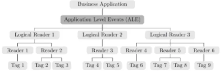
A typical architecture of such a network is shown in Figure 5. A business application is connected to the ALE server. Some physical readers are connected to this server and configured as logical readers. Tags are read by readers and events are sent to the ALE server. The server filters and aggregates events from readers according to specifications received from the business application, and finally sends reports to the application. With the ECSpecs file above-mentioned, only LogicalReader1 and LogicalReader2 events (i.e. tags read) will be used to build the report.
Figure 5: Typical architecture
2.2
Problem statement
A problem arises with the typical architecture shown in Figure 5 when too many tags are read or too many readers are connected to a single ALE. In such cases, a bottleneck appears between readers and the ALE. Indeed, in our typical architecture, if a hundred readers are connected and each reader detects a thousand of tags simultaneously, the network may not be able to manage so many readers events and the ALE may not be able to process so much data. So
8 Schmidt, Dagher, Quilez, Mitton & Simplot-Ryl
one ALE for managing all company warehouses readers is not scalable enough. A solution would be to duplicate ALE engines.
Figure 6 presents the same case as above but with two ALE engines. By using a load balancing approach [9], this solves the problem of overload of work for ALEs. This solution offers mechanisms to know how loaded are the different ALEs and to migrate ECSpecs from an over-loaded one to some under-loaded other. It provides also a way to migrate readers concerned by the newly mi-grated ECSpec in order to allow the under-loaded ALE to perform the operation described in the above-mentioned ECSpec.
Figure 6: Two ALEs in two warehouses
But solving the problem of overload of work for ALEs arises three new prob-lems: (i) conflicts: if an ALE is overloaded by four ECSpecs that all use a same reader, ECSpecs are not movable, and this ALE will remain overloaded; (ii) network overload: if the overloaded ALE and its readers are located in Japan and the under-loaded ALE in Europe, after the migration of one ECSpecs from Japan (and readers reconnection), all reader events will have to cross the world, which may not be a scalable and economic solution in term of bandwidth oc-cupancy, energy saving and latency; (iii) transparency for business application: if the business application goal is to perform an inventory of all items, 1) it has to send a specification to each ALE involved in the inventory process, and
2) it receives one report per ALE that may have redundant data and 3) needs
to filter and aggregate once again (e.g. tag 5 in Figure 6 may be read by both Reader 3 and Reader 4 if they are close), what is not the role of the business application. And this only puts off the bottleneck problem between the ALE and the business application. Indeed, this architecture does not offer scalability when the number of ALEs increases consequently.
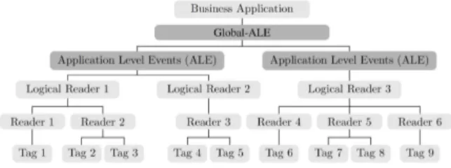
In order to solve the problem of transparency, Liu et al. [10] propose a Global ALE that splits ECSpecs before sending them to right Sub-ALEs and merges ECReports received from above-mentioned Sub-ALEs. A Connection Pool manages the data received from the reader layer (i.e. the EPC Pool) and the Sub-ALEs pool (with CPU usage, IP address, etc.). This is the component that schedules procedures.
By doing so, they provide solution for the ALEs works overloading prob-lem (i.e. by reducing the number of readers managed by the ALE) and the transparency to higher level of the network (i.e. business applications). But the system is centralized like the typical architecture (Figure 5) and a bottleneck may appear between Sub-ALEs and the Global ALE.
The ALE overload problem is beyond the scope of this paper. Our solution is to distribute ALEs and to give them mechanisms to process specifications and
Figure 7: Global ALE Architecture
reports (split ECSpecs and send part to concerned ALEs, receive and merge reports) providing transparency to business application. Each ALE will be distributed as a node like in peer-to-peer using a dynamic hash table (DHT), concept explained in Section 3. Here, it focuses on scalability, transparency for upper layers and network load, providing a solution for above-mentioned prob-lems, and compatibility with existing EPC ALE standard, providing reusability for already developed or future business applications.
3
DHT and lookup in P2P systems
3.1
Preliminaries
Providing a scalable and efficient location service in the context of self-organizing systems is a non–trivial problem, due to the spontaneity of networks. This requires a dynamic association between identification and location of a node, and the specification of a mechanism to manage this association. Furthermore, there is the need for minimizing the control message overhead for routing or location discovery. An efficient solution is to perform an indirect routing [11][12][13].
An indirect routing operation is performed in two steps: (i) first locate the target and then (ii) communicate with the target. The main difference with classic routing is how the target is located. Instead of using a big routing ta-ble containing all information and addresses of targets, in indirect routing, this table is distributed among the nodes and is accessible via a hash function. Dis-tributed Hash Tables (DHT) represent the basis of indirect routing. Basically, they provide a general mapping between any information and a location estab-lishing then a location-independent routing layer. This allows the network to decouple the location of a node from the location itself. With this approach, the information can be totally distributed, which is important for achieving scalability in large scale networks.
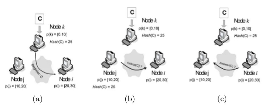
Figure 8 shows mechanisms used to register or to retrieve information with indirect routing and DHT. Suppose node k wants to register a content C. Dur-ing the register operation (Figure 8(a)), node k hashes the content C to store and registers information about this content in the corresponding node (node i is responsible of the address space [20, 30] and Hash(C) = 25, so node i is re-sponsible of this content). When a node wants to retrieve some content, it first calculates the hash of the content and then contacts the corresponding node. Figure 8(b) shows node j hashing C and contacting node i, responsible of the address space [20, 30]. Then node i answers to j with information about C.
10 Schmidt, Dagher, Quilez, Mitton & Simplot-Ryl
(a) (b) (c)
Figure 8: (a) Node k stores content C, and registers information about C on node i which is its rendezvous node. (b) Lookup phase of node j to contact the rendezvous node of C. (c) Lookup answer with information about C.
Spontaneity of the networks requires the system to be able to manage node arrivals, node departures and node failures
Node Arrival: When a node enters the network, it first contacts a DHT node. Then, a partition of the logical address space is assigned to this new node. This arrival implies an update of the routing information in the system. Finally, it retrieves all (key, value) pairs under its responsibility from the node that stored them previously.
Node Departure: When a node leaves the network, it notifies the system before leaving. This notification allows the system managing the departure of this node. This is done by (i) re-assigning the leaving node partition of the logical address space to other nodes and (ii) registering all (key, value) pairs of the leaving node into these new corresponding nodes.
Node Failure: When a node fails, the data it stored is lost. In order to avoid this problem, some DHT use data replication and store multiple copies on different nodes. Therefore, a node failure leads to a temporary loss of application data until the data is refreshed.
3.2
Related works
DHT-based peer-to-peer (p2p) systems are widely spread in files sharing. Pro-viding a general mapping between location and information, such systems offer an easy way to share data. A new node with data just has to register its data in the database, and then can be questioned by other nodes in order to retrieve its shared data. The first software we introduce is Napster [14]. This network relies on a DHT that map nodes address to files they share. The main problem of Napster is that the table of mapping is totally centralized. This means that requests for a file are always sent to the server that store the map table. This is not really scalable because it depends on the reliability of the server. This is solved in Gnutella [15], a totally decentralized p2p file sharing system. But the problem of gnutella rises during the lookup operation (i.e. retrieve at least one node address that contains the data). A node has to broadcast the network to know where is stored the needed data. This is not efficient and may cause over-load of the network. Following systems solve these two problems. They propose
decentralized systems with more efficient lookup operation than broadcast. For more details, we invite the reader to check the referred papers.
Chord: In [16], authors propose a circled virtual space. Each node is responsi-ble for a partition of this circled virtual space. The main advantage of Chord is its robustness. Indeed, Chord allows a node to join and leave, reflecting changes to the rest of the network. Moreover, its lookup operation always results in success or definitive failure in predictable time. Each node maintains about O(log N ) and a lookup operation is performed in O(log N ) (with N the number of nodes in the system).
CAN:The particularity of CAN [17] is its virtual space: a d-dimensional Carte-sian coordinate space on a d-torus. Mapped with geographical coordinates, it can provide a link between the virtual space and physical space (with d = 3). The problem is that this additional complexity due to its d dimension costs. The required information for each node is about O(d) and the complexity of the lookup operation is O(dN1/d). As we can see, the information to be stored by
each node is not depending on N, and CAN complexity matches with Chord’s one with d = log N.
Pastry: Pastry [18] uses a circular virtual space, like in Chord. The routing protocol in Pastry is a prefix-based. It means that routing request are forwarded to the node with the ID with the biggest common prefix with the data ID needed until reaching the right node.
Tapestry: Tapestry [19] focuses on proximity. In order to reduce network latency, the request visits closest nodes from the one which is performing the query. This research of proximity increases the complexity of operation such as join, leave or failure.
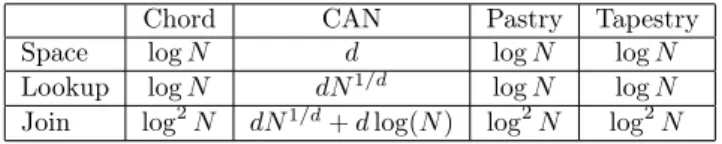
As presented before, three major concepts of p2p are decentralization, over-load of the network and dynamics (i.e. nodes leaving and joining the system). Figure 9 summarizes costs of each presented systems. The row Space indicates the amount of data that need to be stored and maintained in each node. The
Lookup and Join rows are costs for respectively the lookup phase (i.e. searching
for a node that contains the needed data) and the join (or leave) phase, when a new node enters (or leaves) the system.
Chord CAN Pastry Tapestry Space log N d log N log N Lookup log N dN1/d log N log N
Join log2N dN1/d+ d log(N ) log2N log2N
Figure 9: Costs of p2p algorithms
4
DHT-based distributed ALE
4.1
P2P system
Providing scalability, dynamics, and preventing network overload, P2P systems solve some parts of our problems. The first step is to map P2P elements with RFID middleware architecture. In our solution, ALEs are nodes, and readers are objects to store and share by the system. In the ALE, readers are configured as
12 Schmidt, Dagher, Quilez, Mitton & Simplot-Ryl
logical reader via LRSpecs files. The configuration of logical reader is simple, a logical reader can be composite or not. If not, it defines one physical reader with informations needed to contact it: name, connector (LLRP, RP, or proprietary adapter), IP address and port (in case of network reader), etc. If a logical reader is composite, it is composed by other logical readers (composite or not). Figure 10 and Figure 11 shows respectively the definition of a non-composite LogicalReader1 and a composite LogicalReader3 composed by LogicalReader1 and LogicalReader2.
1. <?xml version="1.0" encoding="UTF-8" standalone="yes"?> 2. <ns3:LRSpec xmlns:ns2="urn:epcglobal:ale:wsdl:1" 3. xmlns:ns3="urn:epcglobal:ale:xsd:1"> 4. <isComposite>false</isComposite> 5. <readers/> 6. <properties> 7. <property> 8. <name>ReaderType</name> 9. <value>LLRPAdaptor</value> 10. </property> 11. <property> 12. <name>Description</name> 13. <value>LLRP reader</value> 14. </property> 15. <property> 16. <name>PhysicalReaderName</name> 17. <value>LogicalReader1</value> 18. </property> 19. <property> 20. <name>ip</name> 21. <value>localhost</value> 22. </property> 23. <property> 24. <name>port</name> 25. <value>5084</value> 26. </property> 27. <property> 28. <name>clientInitiated</name> 29. <value>true</value> 30. </property> 31. </properties> 32. </ns3:LRSpec>
Figure 10: LRSpecs file defining a non-composite logical reader
1. <?xml version="1.0" encoding="UTF-8" standalone="yes"?> 2. <ns3:LRSpec xmlns:ns2="urn:epcglobal:ale:wsdl:1" 3. xmlns:ns3="urn:epcglobal:ale:xsd:1"> 4. <isComposite>true</isComposite> 5. <readers> 6. <reader>LogicalReader1</reader> 7. <reader>LogicalReader2</reader> 8. </readers> 9. <properties/> 10. </ns3:LRSpec>
Figure 11: LRSpecs file defining a composite logical reader
As physical readers are objects to share, we use for now only non-composite logical readers. By uniquely assigning the value of the property
PhysicalReader-Name (lines 16-17 of Figure 10), this value is used as the key for the DHT. The
information needed in order to interrogate the ALE connected to the reader is depending on its implementation. In our case, it is the url of the webservice
it provides. For the rest of this section, terms ALE or node are both used to define nodes of the p2p network, which are also ALE. Terms reader or object are used for non-composite logical readers and the term record represents a pair < readerN ame, aleU rl >.
The P2P system provides several operations in order to add or delete records, retrieve information stored for a key, join or leave the network, and so on. In our case, the distributed ALE is built upon the Chord protocol.
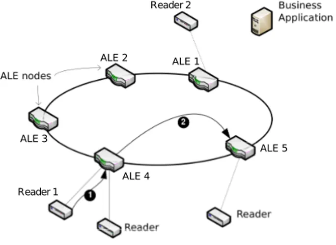
Now that a p2p network structure is established for all connected ALEs, Figure 12 shows a node performing a record of a new reader connected to it. Reader 1 is first configured locally by the ALE 4 (arrow ❶), and then, ALE 4 uses the hash function to know where it has to declare this new reader. Finally, the node ALE 4 sends the pair < readerName, aleUrl > to the contact node ALE 5 (arrow ❷). Once this is done, every node can retrieve the url of the ALE 4, managing the Reader 1.
ALE nodes Reader 2 Reader 1 ALE 1 ALE 2 ALE 3 ALE 4 ALE 5
Figure 12: Recording a new reader in distributed ALE system
It is the same mechanism as in Figure 8(a) where node k would be ALE 4, node i would be ALE 5, content C would be Reader 1 and information about C would be the URL of ALE 4 managing Reader 1.
4.2
Runtime mechanisms
Network structure is done, readers are recorded, we can now use the distributed ALE system. When a business application wants to perform an operation, it first has to define specifications of the operation (i.e. the ECSpecs) in accordance with EPCglobal standard. Figure 3 will be used for presenting the splitting op-eration. It declares two logical readers involved in the process (LogicalReader1 and LogicalReader2, line 5 and 6). The boundarySpec section explains that this operation has to be repeated every 10 seconds with a duration of 9.5 seconds (line 8 to 10).The reportSpecs configures the ALE to report all the epc of tags present in the field of the reader.
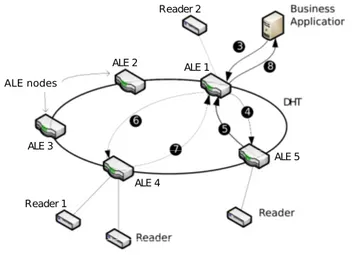
Figure 13 presents a distributed ALE system with the different steps per-formed at runtime in order to use the system with the above-mentioned
EC-14 Schmidt, Dagher, Quilez, Mitton & Simplot-Ryl
Specs (i.e. spread specifications sent by business applications and merge re-ports). The LogicalReader1 and LogicalReader2 in the ECSpecs are configured as non-composite and respectively parameter Reader 1 (connected to ALE 4) and Reader 2 (connected to ALE 1). When a business application wants to per-form the inventory operation on Reader 1 and Reader 2, it first has to send the ECSpecs XML file to an ALE belonging to the network (arrow ❸). It may be the closest, the less loaded or whatever, it depends on the implementation and/or configuration choices. ALE 1 that receives the specification knows its readers and can know that Reader 1 involved in the ECSpecs is not connected to it, but Reader 2 is. Here comes the hash function, which allows ALE 1 questioning the p2p structure. By hashing the logical reader 1 name LogicalReader1, ALE 1 knows the ALE responsible to store information about this EPC (ALE 5), and can query it (arrow ❹). ALE 5 then answers with the url of ALE 4 connected to the Reader 1 (arrow ❺). Then ALE 1 can split the ECSpecs files and sends one to ALE 4 (arrow ❻). The splitting operation is easy here, we just need to split readers in two ECSpecs file, one for ALE 1 with only LogicalReader2 (Figure 14) and one for ALE 4 with only LogicalReader1 (Figure 15).
ALE nodes Reader 1 Reader 2 ALE 1 ALE 3 ALE 2 ALE 4 ALE 5
Figure 13: Report generation steps in distributed ALE system
The first ECSPecs is kept and used by ALE 1 while the second is sent to ALE 4 via the webservice url received from the lookup operation. The two involved ALEs can now process locally with their ECSpecs. It means configuring local reader, launching the inventory, filtering and aggregating reader events, building the report. Once reports are ready, ALE 1 knows that a second report is needed, and waits for it. ALE 4 will send its reports to ALE 1 (arrow ❼) which can then merge reports. Finally, ALE 1, the contacted node, send the report to the business application (arrow ❽).
This is a simple example that shows the case where multiple distant read-ers (and so on multiple ALEs) are involved in the ECSpecs. The merge step is important in order to remove double record or manage groups and keeping the transparency towards applications. Indeed, an ECSpecs can specify some grouping patterns. Grouping patterns allow to group identifiers in the report (e.g. group by manufacturer, group by item type, etc.). Before sending the
1. <?xml version="1.0" encoding="UTF-8" standalone="yes"?> 2. <ns2:ECSpec xmlns:ns2="urn:epcglobal:ale:xsd:1"> 3. <logicalReaders> 4. <logicalReader>LogicalReader2</logicalReader> 5. </logicalReaders> 6. <boundarySpec> 7. <repeatPeriod unit="MS">10000</repeatPeriod> 8. <duration unit="MS">9500</duration> 9. <stableSetInterval unit="MS">0</stableSetInterval> 10. </boundarySpec> 11. <reportSpecs> 12. <reportSpec> 13. <reportSet set="CURRENT"/> 14. <output includeTag="true"/> 15. </reportSpec> 16. </reportSpecs> 17. </ns2:ECSpec>
Figure 14: ECSpecs part for ALE 1
1. <?xml version="1.0" encoding="UTF-8" standalone="yes"?> 2. <ns2:ECSpec xmlns:ns2="urn:epcglobal:ale:xsd:1"> 3. <logicalReaders> 4. <logicalReader>LogicalReader1</logicalReader> 5. </logicalReaders> 6. <boundarySpec> 7. <repeatPeriod unit="MS">10000</repeatPeriod> 8. <duration unit="MS">9500</duration> 9. <stableSetInterval unit="MS">0</stableSetInterval> 10. </boundarySpec> 11. <reportSpecs> 12. <reportSpec> 13. <reportSet set="CURRENT"/> 14. <output includeTag="true"/> 15. </reportSpec> 16. </reportSpecs> 17. </ns2:ECSpec>
Figure 15: ECSpecs part for ALE 4
nal report to the business application, ALE 1 has to check and rebuild groups. This is the main characteristic that provides a complete transparency for business applications. They don’t have to split and merge specs and reports themselves. The second characteristic for transparency is the use of the ALE Reading API and ALE Logical Reader API defined in ALE standard as interface between nodes or for upper layer of the middleware. This EPCglobal stan-dards compliance provides an easy way to replace existing any EPCglobal ALE by a distributed one without re-write code of any business application. Finally, building the ALE component of a middleware upon a p2p protocol provides the needed scalability, dynamicity and robustness.
The following section presents some results of comparison between a normal ALE and the distributed ALE.
5
Results
It is worth noting that experimental results will greatly rely on implementation. In our case, starting from the Fosstrak [20] implementation of the TDT, which has for contributors some people from Auto-ID Lab and ETH Zurich, we have
16 Schmidt, Dagher, Quilez, Mitton & Simplot-Ryl
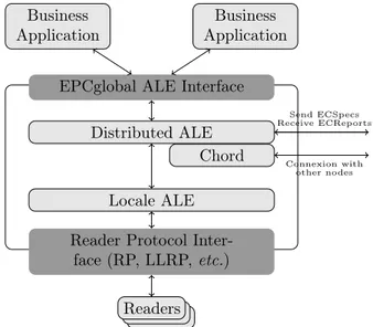
plugged it to a java implementation of the Chord protocol called openchord [21]. The structure of our solution is shown in Figure 16.
Business Application
Business Application
EPCglobal ALE Interface Distributed ALE
Chord Locale ALE Reader Protocol
Inter-face (RP, LLRP, etc.) R R Readers Send ECSpecs Receive ECReports Connexion with other nodes
Figure 16: Software architecture of a distributed ALE
The distributed ALE component receives specifications from business appli-cations, and then, using its own readers database and the lookup operation of the Chord component, is able to split ECSpecs and to send them to right ALE. The local ALE component is the Fosstrak ALE implementation.
In order to evaluate the performances of our solution, we use LLRP events generators. After being connected to an ALE, they simply send reports. We have configured ten tags per reader. The first measures are done using the fos-strak ALE and four LLRP readers. We then measure our solution, but not in its distributed version (e.g. only one node in the Chord network, no lookup opera-tion). Results are close and show that the additional process for distributing the ALEs (e.g. the Distributed ALEs and the Chord components) do not reduce the performance in a significant way: after multiple executions of the common above mentioned ECSpecs, the average execution time with the fosstrak ALE is about 4328ms against 4746ms with our solution. When we distribute the four readers among two ALEs, this average comes to 5915ms. Yet, the latency introduced by the additional functionalities is less than 10% of the nominal case by providing scalability and reliability and preventing ALE to crash. When the number of readers increases, the latency decreases and thus relieving in the same time the ALE engines which can run more quickly. The real benefits of our solution lay in the mechanism of p2p, which provides scalability. In the case one ALE is not efficient (i.e. with a hundred of readers), we just have to add one ALE/node in the network. In addition, new functionalities use is completely transparent for already developed business applications and can be easily integrated in current EPC standards.
We have chosen to use a complete library for the local ALE (here Fosstrak) because it offers a way to plug an other ALE engine component. Indeed, if a new ALE component comes to be available, and provides EPCGlobal ALE interface
via web services mechanisms, we can switch easily this component and test the new one. But note this is not the optimal implementation since ALEs/nodes communicate via web services, using XML files for exchange specifications and reports, which introduces an important delay. By introducing an other interface between nodes with serialized object rather than XML through web services, performances should be increased. This is kept for future work.
6
Conclusion
In the scope of the Internet of Things, where all objects is carrying an unique identifier, standards have to be defined in order to retrieve informations about objects all over the world. Auto-ID Labs and EPCglobal Inc. define standards for such kind of infrastructures. They define a way to encode ID in RFID, to retrieve data from RFID, to filter and aggregate those IDs into well constructed reports for business applications, etc.building an RFID middleware. By doing so, business applications can query this middleware without knowledge about reader protocols, network communications, and so on. A problem rises when too many readers are connected to the middleware. In one hand this overload the work of the ALE, or in the other hand, business applications have to query all ALEs involved.
Using the p2p and DHT principles, we have provide mechanisms that solve the problem of ALEs overload (e.g. by distributing readers among them) while keeping transparency for business applications. This distributed application level event engine is EPCglobal standards compliant, scalable, robust and trans-parent.
Future works will focus on finding a way to define distributed logical readers (e.g. composite logical reader with distant physical readers), and to study the possibility of the CAN protocol instead of Chord in order to use the benefits of a 2-dimensional virtual space. Linked with the distributed logical readers, and geographical coordinates, it may offer the possiblity to define geographical logi-cal readers: querying the big french logilogi-cal reader will query all physilogi-cal readers in France, or to automatically define logical reader depending on geographical position or any other information.
Acknowledgments
This work is partly supported by FP7 Aspire European Project [22], the french project ICOM from the PICOM [23] (Pôle de compétitivité des Industries du COMmerce) and the French ANR project WINGS [24] .
References
[1] Auto-ID Labs, http://www.autoidlabs.org [2] EPCGlobal Inc., http://www.epcglobal.org
[3] EPCGlobal Inc., EPCglobal Reader Protocol (1.1)
18 Schmidt, Dagher, Quilez, Mitton & Simplot-Ryl
[5] EPCGlobal Inc., EPCglobal Architecture Framework (1.3) [6] GS1, GS1 General Specifications v10
[7] EPCGlobal Inc., EPCglobal Tag Data Standards Version 1.4
[8] L. Schmidt, N. Mitton, and D. Simplot-Ryl. Towards Unified Tag Data Translation for the Internet of Things. Wireless Communication Society,
Vehicular Technology, Information Theoryand Aerospace & Electronics Sys-tems Technology (VITAE’09), Aalborg, Denmark, 2009.
[9] Jae Geol Park, Heung Seok Chae, and Eul Seok So. A dynamic load balanc-ing approach based on the standard rfid middleware architecture. In ICEBE
’07: Proceedings of the IEEE International Conference on e-Business En-gineering, pages 337–340, Washington, DC, USA, 2007. IEEE Computer
Society.
[10] Fagui Liu, Yuzhu Jie, and Wei Hu. Distributed ale in rfid middleware. In Wireless Communications, Networking and Mobile Computing, 2008.
WiCOM ’08. 4th International Conference on, pages 1–5, Oct. 2008.
[11] J. P. Hubaux, Th. Gross, J. Y. Le Boudec, and M. Vetterli. Towards self-organized mobile ad hoc networks: the terminodes project. IEEE
Com-munications Magazine, 39(1):118–124, January 2001.
[12] J. Li, J. Jannotti, D. S. J. De Couto, D. R. Karger, and R. Morris. A scalable location service for geographic ad hoc routing. In Proceedings of
ACM Mobicom, Boston, MA, August 2000.
[13] Y. Xue, B. Li, and K. Nahrstedt. A scalable location management scheme in mobile ad-hoc networks. In Proceedings of IEEE Conference on Local
Computer Networks (LCN).
[14] Napster. http://www.napster.com/
[15] The Gnutella protocol specification, 2000.
http://www9.limewire.com/developer/gnutella_protocol_0.4.pdf/
[16] I. Stoica, R. Morris, D. Liben-Nowell, D. R. Karger, M. F. Kaashoek, F. Dabek, and H. Balakrishnan. Chord: a scalable peer-to-peer lookup protocol for internet applications. Networking, IEEE/ACM Transactions
on, 11(1):17–32, 2003.
[17] S. Ratnasamy, P. Francis, M. Handley, R. Karp and S. Shenker. A Scal-able Content-AddressScal-able Network. In Proceedings of ACM SIGCOMM, San Diego, CA, August 2001.
[18] A. Rowstron and P. Druschel. Pastry: Scalable, decentralized object lo-cation, and routing for large-scale peer-to-peer systems. In Proceedings of
the IFIP/ACM International Conference on Distributed Systems Platforms,
Heidelberg, p.329-350, November 12-16, 2001
[19] K. Hildrum, J.D. Kubiatowicz, S. Rao and B.Y. Zhao. Distributed object location in a dynamic network In Proceedings ot the 14th ACM Symp. on
Parallel Algorithms and Architectures, August 2002.
[20] Fosstrak: Open Source RFID Software Platform, http://www.fosstrak.org/ [21] Open Chord, http://open-chord.sourceforge.net/
[22] Aspire European Project, http://www.fp7-aspire.eu/
[23] Pôle de compétitivité des Industries du COMmerce, http://www.picom.fr/ [24] WINGS ANR Project, http://www.wings-project.fr/
Centre de recherche INRIA Lille – Nord Europe
Parc Scientifique de la Haute Borne - 40, avenue Halley - 59650 Villeneuve d’Ascq (France)
Centre de recherche INRIA Bordeaux – Sud Ouest : Domaine Universitaire - 351, cours de la Libération - 33405 Talence Cedex Centre de recherche INRIA Grenoble – Rhône-Alpes : 655, avenue de l’Europe - 38334 Montbonnot Saint-Ismier
Centre de recherche INRIA Nancy – Grand Est : LORIA, Technopôle de Nancy-Brabois - Campus scientifique 615, rue du Jardin Botanique - BP 101 - 54602 Villers-lès-Nancy Cedex
Centre de recherche INRIA Paris – Rocquencourt : Domaine de Voluceau - Rocquencourt - BP 105 - 78153 Le Chesnay Cedex Centre de recherche INRIA Rennes – Bretagne Atlantique : IRISA, Campus universitaire de Beaulieu - 35042 Rennes Cedex Centre de recherche INRIA Saclay – Île-de-France : Parc Orsay Université - ZAC des Vignes : 4, rue Jacques Monod - 91893 Orsay Cedex
Centre de recherche INRIA Sophia Antipolis – Méditerranée : 2004, route des Lucioles - BP 93 - 06902 Sophia Antipolis Cedex
Éditeur
INRIA - Domaine de Voluceau - Rocquencourt, BP 105 - 78153 Le Chesnay Cedex (France)
http://www.inria.fr
![Figure 6 presents the same case as above but with two ALE engines. By using a load balancing approach [9], this solves the problem of overload of work for ALEs](https://thumb-eu.123doks.com/thumbv2/123doknet/12764998.359957/11.892.264.626.397.518/figure-presents-engines-balancing-approach-solves-problem-overload.webp)