The effect of ICRF and LHCD waveguide and launcher location on
tritium breeding ratio and radiation damage in fusion reactors
By
Jennifer Marie Sierchio
B.S., University of Arizona (2011)
S.M., Massachusetts Institute of Technology (2014)
Submitted to the Department of Nuclear Science and Engineering
in partial fulfillment for the requirements for the degree of
Master of Science in Nuclear Science and Engineering
at the
MASSACHUSETTS INSTITUTE OF TECHNOLOGY
February 2016
C Jennifer Marie Sierchio, MMXVI. All rights reserved.
The author hereby grants to MIT permission to reproduce and to
distribute publically paper and electronic copies of this thesis document
in whole or in part in any medium now known or hereafter created.
Signature of Author ...
Certified by ...
Certified by ...
Accepted by ...
ASSACHUSETTS INSTITUTE OF TECHNOLOGYMAY 11
2016
LIBRARIES
ARCHWiES
Signature redacted
Department of Nuclear Science and Engineering
January 15, 2016
Signature redacted
Dennis G. Whyte
Department Head and Professor of Nuclear Science and Engineering
Thesis supervisor
Signature redacted
...
Michael Short
Assistant Professor of Nuclear Science and Engineering
Thesis Reader
Signature redacted
. . . ....
.
. . . ...
Ju Li
The effect of ICRF and LHCD waveguide and launcher location on
tritium breeding ratio and radiation damage in fusion reactors
by
Jennifer Marie Sierchio
Submitted to the Department of Nuclear Science and Engineering on January 15, 2016, in partial fulfillment of the
requirements for the degree of
Master of Science in Nuclear Science and Engineering
Abstract
In most tokamak fusion reactor designs, ICRF (Ion Cyclotron Range of Frequencies) and LH (Lower Hybrid) radio frequency (RF) waves used to heat the plasma and drive current are launched from the low-field, outboard side where there is more access space. It has recently been proposed to launch these waves from the high-field side [1-3], which increases current-drive efficiency, allows for better wave penetration, and has favorable scrape-off-layer and plasma-material interaction characteristics [4]. However the poloidal location and size of RF launchers will also affect important aspects of the neutronics of the tokamak fusion design, i.e. how the 14.1 MeV neutrons born out of the deuterium-tritium (D-T) fusion reaction interact with the surrounding blanket and structures. The goal of this thesis is to assess the dependence of RF launcher poloidal location on the important neutronics parameters of tritium fuel breeding, launcher damage and activation.
To determine the effects of waveguide and antenna location on Tritium Breeding Ratio (TBR), damage, and activation, the MCNP Transport Code was used, as well as the EASY 2010 activation package to analyze the activation of the vacuum vessel components. A simple geometry was designed for MCNP, based on the original ARC model [1]. Seven locations for the waveguides and antenna were chosen: the inner and outer midplane, the inner and outer upper corners, two spaces between the midplane (inboard and outboard), and a central location directly above the vacuum vessel. TBR, DPA, and helium concentration were calculated at all seven points to find the optimal location for the waveguides and antenna. Four blanket materials were
chosen: two liquid blankets (FliBe and Pb-17Li) and two solid blankets (Li4SiO4 and Li2TiO3).
This was to test whether or not blanket material affects the optimal location of the launchers. We find that from the neutronics point of view the overall optimal location is the inboard upper corner, which minimizes DPA and helium concentration in the antenna and waveguide, and maximizes TBR. DPA in the waveguide was minimized when placed in the outboard upper corner, although the difference in DPA between the two locations was small. While TBR was maximized at the top of the vacuum vessel, the differences in TBR between all locations was less than 1%. These results reinforce the choice of inside, upper corner launch as the optimal location for current drive, launcher protection and neutronics.
Activation was also assessed for the vacuum vessel, both without and with the waveguides and antenna, assuming irradiation times of one week, one month, and one year. Overall, activation was significant in the vacuum vessel, as expected, due to the use of Inconel
718. The IAEA recycling limit could be achieved, regardless of irradiation time. The dominant
isotopes present after irradiation differed when the irradiation time was one week versus one month or one year. Activation was also assessed in the waveguides and antenna for the cases of the launchers being placed at the outboard midplane versus the inboard corner. The activation in the antenna was shown to be reduced by a factor of two and in the waveguides by a factor of four, when the launchers were placed in the inboard corner.
Thesis supervisor: Dennis G. Whyte
Title: Professor and Head of the Department of Nuclear Science and Engineering
Thesis reader: Michael Short
Acknowledgments
I would like to thank Professor Dennis Whyte for supervising this thesis, and Professor Michael
Short for serving as thesis reader. Their comments and suggestions throughout the research for this work as well as for the thesis itself have proved invaluable.
My parents and brother deserve a tremendous amount of gratitude for their constant support
during graduate school and for reminding me of what actually matters in this life.
Ian Faust, Jude Safo, Caleb Waugh, and Dan Kwak - true friends are there even when things get tough. Thank you for being true friends.
Last, but certainly not least, I would like to thank Adam Brooks for his unwavering love and support during my time at MIT. You are simply the best, and I cannot wait to begin our adventure together.
This research was funded, in part, by the National Science Foundation Graduate Research Fellowship Program.
Contents
1
Introduction ... 151.1 Fusion energy and tokamaks ... 16
1.2 Fusion energy extraction: general reactor design ... 19
1.3 Heating and current drive in tokamaks ... 20
1.4 M otivation for this thesis ... 22
2 Review of fusion reactor designs ... 24
2.1 The ARC reactor and blanket designs ... 24
2.1.1 The ARC reactor ... 24
2.1.2 Blanket designs ... 28
2.2 Design targets for TBR and damage rates ... 29
2.2.1 Tritium breeding ratio ... 29
2.2.2 Acceptable damage and activation rates ... 30
3 Neutronics and the 2-D MCNP model ... 32
3.1 Introduction to the underlying theory behind MCNP ... 32
3.2 MCNP waveguide and antenna design ... 34
3.3 MCNP models used for this thesis ... 38
3.4 Test setup with materials and location choices ... 40
4 Blanket design considerations ... 42
4.1 Blanket thickness ... 42
4.2 Effect of neutron multiplier ... 44
4.3 Placement of vacuum vessel ... 45
5 TBR, DPA, and helium retention results from MCNP ... 47
5.1 Example MCNP output ... 47
5.2 Overall results of the scoping study on launcher poloidal location ... 52
5.3 Comparison of two different waveguide structures ... 54
6 Vacuum vessel and waveguide activation ... 56
6.2 EASY 2010 and input methodology ... 57
6.3 Vacuum vessel activation results ... 60
6.4 Blanket and waveguide activation results ... 63
7 Summary, future work, and conclusions ... 66
7.1 Summary of the original research question and results ... 66
7.2 Caveats and future work ... 70
7.3 Conclusions ... 72
8 B ibliography ... 73
A Example MCNP cell and surface cards input file ... 77
B Data tables for the four tested blankets ... 80
List of Figures
1.1 Schematic of the coils generating the toroidal and poloidal magnetic fields... 17 1.2 Tokamak cross-section with minor (r) and major (R) radial directions, and poloidal (0)
and toroidal (q) angles labeled. The central axis (or major axis of symmetry) is the vertical line down the middle. The major radius (R) goes from the central axis to the center of the plasm a ... 18 1.3 General diagram of a full fusion power plant, with a blanket, superconducting magnets
and electricity generation ... 20 2.1 CAD model of the MIT ARC reactor, with a person shown for scale. The plasma is in
yellow with a tight-fitting vacuum vessel, immersion blanket tank, and connections in aqua, superconductor coils in brown, vertical field coils in green, and structural
com ponents in grey ... 25
2.2 MCNP model of the ARC reactor. The plasma is shown in blue and is surrounded by a
multi-component vacuum vessel, which is suspended by a support column shown in red. The distance from the far left to the center of the plasma is 3.3 m (major radius), and one-half of the midplane distance between ends of the vacuum vessel is 1.1 m (minor radius). Figure not to scale ... 26 2.3 Zoom (1:4.72 scale) in of the outer midplane region of the vacuum vessel ... 27 3.1 Outboard midplane waveguide (shown in green) which is bent at right angles to prevent
free-streaming neutrons from reaching the toroidal field magnets, and for the purposes of constructing the MCNP model, is comprised of three different sections... 36
3.2 Alternative design for waveguide design for outer midplane launch (shown in green), in which they come from the top of the blanket tank and bend at an angle into the
appropriate location ... 37 3.3 Stripped model with D-shaped vacuum vessel. Inset shows components of the vacuum
vessel. Sky blue: plasma; orange: tungsten first wall and divertor at bottom of vessel; green: Inconel vacuum vessel; red: cooling channel and blanket (in this case, the blanket is liquid FLiBe); dark blue: beryllium layer. The ellipses in the plasma represent flux
surfaces used to define the neutron source in MCNP. The major radius (distance from center of tokamak to the center of the plasma) is 3.6 m, in part due to the Shafranov shift of the plasma towards the outboard side (as can be seen by the plasma contours) and due to increasing the major radius from 3.3 m to optimize the inboard blanket thickness... 38 3.4 Poloidal angles of the seven test locations where the RF- antennas/launchers were placed
in the MCNP simulations. They include the inboard (1800) and outboard (00) midplane, top of the vacuum vessel (1100), inboard (1260) and outboard corners (760), and in between the midplane and corners on both the inboard (1470) and outboard (500) sides 41
4.1 TBR vs. distance into blanket (cm) for various proposed blanket materials. Note that most of the increase in TBR occurs within the first 40 cm of material and the TBR maximizes at about 70 cm, for most proposed blankets... 43 4.2 TBR vs. thickness of cooling channel (cm). Keeping the first wall and inner vacuum
vessel in place, the cooling channel thickness was incrementally increased from 2 cm up to 10 cm, while keeping the total volume of the blanket tank constant (thus the thickness of the outer blanket decreased). Thickness of all other vacuum vessel components remained the same as mentioned in Chapter 3. The original ARC model was used to generate the data for this figure, without the divertor... 44 4.3 Bar graph illustrating the effects of removing the beryllium multiplier from between the
cooling channel (FLiBe) and the outer vacuum vessel and replacing with FLiBe, and adding an additional cm of beryllium between the coolant and the outer vacuum vessel. In the former case, the removal resulted in a ~13% reduction in TBR, while in the later case, the additional beryllium increased TBR by -5%... 45 4.4 TBR vs. Inboard thickness of the blanket at the midplane. The stripped model was used
for this set of runs, with the inboard thickness being varied from 20 cm to 55 cm (and the outboard thickness being varied from 80 cm to 45 cm), while keeping the tank volume constant, and thus the total thickness capped at 100 cm. The major radius was increased in increments of 5 cm. A midplane inboard thickness of 45 cm and a midplane outboard thickness of 55 cm gave the maximum TBR... 46
5.1 Total TBR in Li4SiO4 vs. poloidal angle. The peak TBR occurs at a poloidal angle of
5.2 DPA rate in the antenna in Li4SiO4 vs. poloidal angle. The DPA is minimized at an angle of about 126', or the inboard corner of the vacuum vessel... 50
5.3 DPA rate in the waveguide in Li4SiO4 vs. poloidal angle. The DPA in the waveguide is
minimized at about 870, or in the outboard corner... 50 5.4 Helium concentration (appm) in the antenna in Li4SiO4 vs. poloidal angle. The helium
concentration is minimized at about 1260, or in the inboard corner... 51
5.5 Helium concentration (appm) in the waveguide in Li4SiO4 vs. poloidal angle. The helium
concentration is minimized for at about 126', or in the inboard corner... 51
6.1 Average neutron fluence (1/cm2/MeV) vs. energy (MeV) for the tungsten first wall (blue), inner vv (red), and outer vv (black) ... 58
List of Tables
2.1 Thicknesses, lengths, and radii for each region in the full model used for this study. Plasma regions are ellipses; the lengths in z- and x- are given. Note that the blanket thickness is given for the midplane ... 27 3.1 Properties and inputs of the waveguide and antenna design used for MCNP ... 37 3.2 Radial thicknesses, poloidal lengths, and major radii for each region in the full MCNP
model used for this study. Plasma regions are ellipses; the lengths in z- and x- are given. The stripped model includes all components except those outside the blanket tank.... 39
3.3 Physical and material properties for the four simplified blankets used for this study, with density, temperature, phase and structure. All materials used a 90% lithium-6
enrichm ent ... 40
5.1 Sample MCNP output for the stripped model at with liquid enriched Li4SiO4 as the
blanket material, and helium gas as the coolant for one FPY, at 147'. DPA/yr and helium concentration are not reported for the coolant and blanket layers, and DPA is not reported
for the beryllium layer. Total TBR is 0.992... 47
5.2 Summary of qualitative descriptions for the optimal locations for TBR, DPA rate, and helium concentration in all four blankets. They are essentially in agreement, meaning that there is no dependence on blanket phase material in determining the optimal location of waveguides and antennas ... 52 5.3 Summary of optimal results for total TBR and DPA rate in all four blankets. The TBR in
the liquid blankets is higher than that in the solid blankets because the liquid blankets also act as their own coolant which provides moderation and breeding in the cooling channel of the double-walled VV. DPA rate is comparable in all four blankets, and is assessed for one FPY ... 53 5.4 Summary of results comparing a traditional waveguide model (coming in from the
outboard midplane) and the waveguide design in the stripped model used for this study.
the two designs. The traditional design has a higher DPA rate and more helium retention in the w aveguides ... 54
6.1 Total and peak neutron fluxes for the first wall and inner and outer vacuum vessels, computed with MCNP. The VITAMIN-J energy group structure was used ... 59 6.2 Total neutron fluence and neutron fluence at 14.1 MeV. Values for the outboard
midplane launcher location are given first and values for the inboard corner launcher location are given second ... 59 6.3 Activity, decay heat, and *total inhalation and ingestion dose immediately after
irradiation and ten years after irradiation, for all nine scenarios. These were computed with no waveguides present ... 61
6.4 Dominant nuclides, percentage of total activity, and half-lives for all nine scenarios,
immediately after irradiation. The dominant nuclides are similar between the inner and
outer vacuum vessel for the three irradiation times, respectively, as is to be expected since the inner and outer vessels are both composed of Inconel 718 ... 62 6.5 Dominant nuclides, percentage of total activity, and half-lives for all nine scenarios, ten
years after irradiation. The dominant nuclides are similar between the inner and outer
vacuum vessel for the three irradiation times, respectively, as is to be expected since the inner and outer vessels are both composed of Inconel 718 ... 62 6.6 Activity, *total inhalation and ingestion dose, and decay heat immediately after
irradiation and ten years after irradiation for the blanket, cooling channel, waveguides, and antenna. Outboard refers to placing the launchers in the outboard midplane location while inboard refers to placing them in the inboard corner. There is a significant
reduction in all three quantities when the launchers are placed in the inboard corner. . 64
6.7 Dominant nuclides, percentage of total activity, and half-lives for the blanket and cooling channel whn the launchers are placed at the outboard midplane ... 65
B. 1 Raw MCNP output for the FLiBe blanket at all seven launcher poloidal locations .... 80
B.2 Raw MCNP output for the Pb-I 7Li blanket at all seven launcher poloidal locations .. .81
B.3 Raw MCNP output for the LiSi404 blanket at all seven launcher poloidal locations ... 82 B.4 Raw MCNP output for the LiTi2O3blanket at all seven launcher poloidal locations ... 83
Chapter
1
Introduction
In most tokamak fusion reactor designs, ICRF (Ion Cyclotron Range of Frequencies) and LH (Lower Hybrid) radio frequency (RF) waves used to heat the plasma and drive current are launched from the low-field, outboard side where there is more access space. It has recently been proposed to launch these waves from the high-field side [1-3], which increases current-drive efficiency, allows for better wave penetration, and has favorable scrape-off-layer and plasma-material interaction characteristics [4]. However the poloidal location and size of RF launchers will also affect important aspects of the neutronics of the tokamak fusion design, i.e. how the 14.1 MeV neutrons born out of the deuterium-tritium (D-T) fusion reaction interact with the surrounding blanket and structures. The goal of this thesis is to assess the dependence of RF launcher poloidal location on the important neutronics parameters of tritium fuel breeding, launcher damage and activation. This introductory chapter is organized as follows. In Section
1.1, the overall motivation for studying fusion is discussed and the optimal plasma geometry and
operating conditions is described. In Section 1.2, a generic fusion reactor design is presented, emphasizing energy extraction mechanisms and damage to the reactor. In Section 1.3, the details of the heating and current drive mechanisms necessary for fusion reactor operation are described. Finally in Section 1.4, the discussion is focused onto the problem of how waveguide location affects the energy extraction and materials damage and the rest of the thesis is motivated.
1.1 Fusion energy and tokamaks
Global climate change, specifically warming due to carbon emissions, and an ever-growing world population looking to industrialize (and consume vast amounts of energy) are two of the most significant issues defining the 21st century. To combat these problems, people are searching for cleaner, more abundant, and more efficient sources of energy.
A possible solution for the world's growing energy and climate crises is thermonuclear
fusion. Scientists have studied fusion as a possible energy source for over sixty years; it is the same process that allows the Sun and all stars to emit light. Fusion occurs when two light atoms "fuse" together to form a heavier atom that is lighter than the sum of the original two. Because of this mass defect between the reactants and the product, kinetic energy is released.
The most relevant reaction for the purposes of practical energy generation involves isotopes of hydrogen, namely deuterium (D) and tritium (T), fusing to form a helium nucleus and a neutron. This D-T reaction has the highest probability of occurring of any hydrogen fusion reaction and is given below [5]:
D + T -+ a + n + 17.6 MeV, (1.1)
Kinematics dictates that the alpha particle (helium nucleus) has 1/5 of the total released energy, or 3.5 MeV, and the neutron has 4/5 of the released energy, or 14.1 MeV. Deuterium is very abundant in Earth's oceans; therefore a readily accessible and inexhaustible supply exists. However, tritium is not naturally abundant in any significant quantity due to its 12.3-year half-life, and thus must be bred by a fusion reactor in a closed fuel cycle within a blanket surrounding the vacuum vessel containing the plasma. Neutrons as products from the original fusion reactions will react with lithium to produce tritons and alphas through two reactions [5]:
n(fast) + 'Li -+ T + a + n(slow) - 2.5MeV, (1.2) n(thermal) + 'Li -- a + T + 4.8 MeV. (1.3)
The breeding process will be described in more detail in Section 1.3 and in Chapters 2 and 4. The fusion of atoms requires extremely high temperatures to provide net energy, on the order of 100 million Kelvin for hydrogen. At these temperatures, the atoms are completely ionized, with the electrons normally in the atoms no longer bound by the Coulombic attraction of their respective nuclei. These free nuclei (ions) and electrons form what is called a plasma [5, 6].
In our Sun, this plasma is confined by gravity; on Earth, we do not have the mass to confine a plasma gravitationally so we must find other means of confinement.
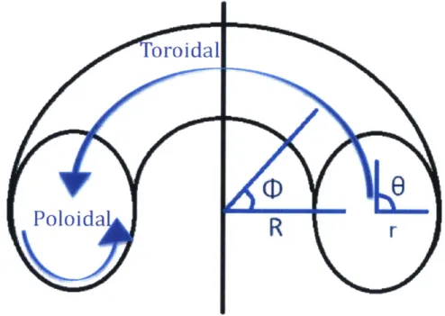
On way to confine plasmas is by using magnetic fields, since charged particles gyrate around the field lines [6]. As one might expect, not all configurations of magnetic field lines will fully confine the plasma. The most successful configuration, a shaped torus called a tokamak, has magnetic fields both the toroidal and the poloidal directions, as shown in Figure 1.1.
r- InIF r m) t I t 4WO-1of
the
tran~sc'rrrerResulta
"IT''a c f Jmagne created by pla:smra curret- currentnt helical
tic field
field
Figure 1.1: Schematic of the coils generating the toroidal and poloidal magnetic fields. Figure
from CEA [7].
The toroidal direction is defined to be around the torus the long way; this direction circles around the device when viewing the device from above. The tokamak plasma has the feature that it is symmetric in the toroidal direction, significantly simplifying its analysis and construction. The poloidal direction is the direction around the torus the short way. If we were to look at a cross section of the torus. not as viewed from above but as sideways, the poloidal direction would follow the lines forming the cross-section on one side of the torus, as shown in Figure 1.2. Notice that the poloidal cross-section need not be circular, and often have a soft D-shape. The
toroidal magnetic field is generated by large field coils outside the vacuum vessel stabilizing the plasma as shown in Figure 1.1. The poloidal magnetic field is primarily generated by the plasma current (with additional coils for shaping and position stability).
Looking at the cross section in Figure 1.2, the center of the plasma is located as a radius we call the major radius, R, if we are measuring from the central axis. We can also define a minor radius, r, to be half the maximum horizontal length of the poloidal cross section. So
overall, this geometry defines two directions, R and r, and two angles
#
in the toroidal direction and 9 in the poloidal direction. The radius of the tokamak at the outboard (outer or larger R) side is greater, by definition, than it is on the inboard (inner or smaller R) side. Drawing a horizontal line from the central axis of the torus through the center of the plasma extending to the outboard side, and then rotating it around the central axis defines what is known as the midplane. [8]Toroidal
Poloid a
Figure 1.2: Tokamak cross-section with minor (r) and major (R) radial directions, and poloidal
(6) and toroidal (q) angles labeled. The central axis (or major axis of symmetry) is the vertical
line down the middle [8]. The major radius (R) goes from the central axis to the center of the plasma.
1.2 Fusion energy extraction: general reactor design
We recall that fuel for the D-T reactions is deuterium obtained from ocean water, and tritium that must be bred through neutron reactions with lithium in a blanket surrounding the plasma vacuum vessel. All neutrons, which are unconfined by the magnetic field, leave the plasma at 14.1 MeV; ostensibly these fast neutrons will react with lithium-7 in Equation 2. Upon first consideration, this seems to be reasonable since lithium-7 makes up 92.5% of natural lithium [9]. However, thisendothermic reaction uses almost 18% of the initial kinetic energy of the neutron, which needs to be extracted for the purposes of generating electricity, and the neutrons are disallowed from this reaction after only a few collisions. The exothermic lithium-6 reaction, however, releases an extra 4.8 MeV of energy, but requires thermalized neutrons [5]. At the very least, the blanket needs to include some mix of lithium-6 and lithium-7.
The blanket also needs to moderate neutrons, for multiple reasons. First is that slow neutrons react with lithium-6 to release net energy, thus increasing the energy released from 17.6 MeV to around ~22 MeV. Second is that, without moderation and capture, neutrons will cause damage to the surrounding materials in the form of swelling from combined radiation damage clustering and helium retention. This damage can severely affect balance of plant and plant lifetime. For example, in the case of waveguides and antennas, damage will reduce the efficiency of RF energy transfer (e.g. due to increases in electrical conductivity), requiring more external power to heat the plasma and lowering the fusion plant's gain. Even more detrimental, significant neutron damage can change the internal structure of the superconducting materials used in the toroidal field coils (to provide a continuous magnetic field), causing them to no longer superconduct after some critical neutron fluence is reached. This effectively shortens plant lifetime. Thus our blanket also needs to moderate neutrons and shield the superconductor toroidal field magnets.
Finally, the neutrons deposit their energy in the blanket in the form of heat. This heat must be extracted and converted to electricity with a heat exchanger and generator. The extraction process requires removal of the blanket, the specifics of which depend on whether the blanket is a liquid or solid. If liquid, the liquid will flow out of the reactor at some rate, the same
rate at which fresh blanket flows in. If solid, the reactor must be opened and the solid components must be removed and replaced.
Moving outward in the minor radius direction from the plasma, a fusion reactor contains a plasma surrounded by a first wall typically made of an erosion-resistant materials such as tungsten. Next comes the blanket composed of lithium and other moderating materials. If solid, the blanket requires no other structural materials and resides inside a vacuum vessel. If the blanket is liquid, then there must be a vacuum vessel in between the first wall and the blanket, usually a steel alloy. The liquid blanket must be held in some tank with pipes to allow flows in and out. Beyond the tank must be insulation and the cryostat containing the magnetic field coils, along with. An example of this arrangement is shown in Figure 1.3
R uperconducting coils
R emote
handlinc-Blankets
--- H e at transfer
process
Heating E lectridty production
Fuel cyde
Figure 1.3. General diagram of a full fusion power plant, with a blanket, superconducting
magnets and electricity generation. From CEA [10].
1.3 Heating and current drive in tokamaks
As mentioned previously, the probability of the D-T reaction occurring maximizes at high temperatures. This actually creates two problems that must be solved: 1) heating the plasma, and 2) containing it. Regarding the former, ideally the charged alpha particles to be confined so they may transfer their energy to the rest of the plasma. If the plasma is ignited, the alpha particles
provide all the heating necessary to maintain plasma temperature. In reality there is a finite amount of external heating provided to the plasma to both maintain temperature (through heating), and control, through manipulation of the plasma's equilibrium. Regarding the latter, along with a toroidal magnetic field, a poloidal magnetic field generated by current in the plasma itself provides the rotational transform necessary for confinement. In a tokamak operating continuously, one must externally drive a significant fraction of the plasma current. Thus in a tokamak configuration, the heating applied to drive the current is a fundamental design choice which is central to determining the power gain of the fusion reactor.
Fortunately, multiple ways to heat the plasma have been proposed and whose viability continues to be shown through current experiments. The most common heating mechanisms include neutral beams and waves launched into the plasma that damp onto particles at certain resonant frequencies (namely, the ion cyclotron frequency and the lower hybrid frequency which are discussed below). Neutral beams will not be discussed further since large ports at the outboard midplane have to be constructed to launch the beams. This leaves many free streaming neutrons, which will be shown later to cause damage the outer materials and magnets.
By excluding neutron beams, this leaves wave launching as a viable option. Briefly, we
will introduce the main types of waves used and general waveguide and antenna design, which will be relevant later in the thesis. We will focus on two waves in particular: the lower hybrid range of frequencies (LH) and the ion cyclotron range of frequencies (ICRF). The reader is referred to [10] for a derivation of these frequencies.
Wave damping in the LH range of frequencies has been found to be effective for current drive. The LH frequency, WLH, is given by solving [I 1]:
i+ e- = 0, (1.4)
ce WLH
where wpe is the electron plasma frequency, w, is the ion plasma frequency, and oce is the electron cyclotron frequency. These are given by [5]:
e fee2 e ni(Ze)2 (1.5)
eEo MiE0
WCe C
where n is the density of the electrons or ions, Z is the charge of the ions, m is the mass of the electrons or the ions in kg, B is the magnetic field strength in T, and co is the permittivity of free space, 8.85x10⁻² F/m. The current drive efficiency is usually written as a figure of merit [11]:
7 120 (1.7)
MW
where I is the plasma current driven by the heating mechanism, R is the major radius of the tokamak, and P is the absorbed power.
The ICRF frequencies used for plasma heating are given above in Equation 1.10, and are typically on the order of 50-100 MHz due to the fact that toroidal magnetic fields of greater than 4 T are generally considered necessary to produce a fusion reactor. The typical value of the LH frequency in magnetic fusion plasmas is 1-10 GHz and efficiencies of 20-50% can be obtained.
Both LH and ICRF launchers need to be close to the plasma due to the presence of cutoff regions, i.e. locations is plasma parameter space whereby their dispersion relationships are not allowed to propagate in the plasma. Note that vacuum propagation of these ICRF and LH waves is not permitted since the RF frequency is substantially below the electron plasma frequency. The antennas are thus placed inside the vacuum vessel containing the plasma such that they are close in minor radius position to the periphery of the fusion plasma. Current designs place both the antennas and the waveguides that carry the RF power at the outboard midplane for easier geometric access. As will be shown later, this placement is not the ideal location for a variety of reasons.
1.4 Motivation for this thesis
In most fusion reactor designs, ICRF and LH radio frequency waves used to heat the plasma and drive current are launched from the low-field, outboard side where there is more access space. As mentioned above, it has been recently proposed to launch these waves from the high-field side [1-3], which increases current drive efficiency, allows for better wave penetration, and has favorable scrape-off-layer and plasma-material interaction characteristics [4]. The
implements high-field side launch through a vacuum vessel within a liquid immersion blanket
[1]. ARC will be further discussed in the next chapter.
As discussed above, one major consequence of high-energy neutrons is damage to materials. This is particularly problematic for the heating and current drive waveguides and antennas that must be very close to the plasma for proper wave penetration; they will be exposed to a high-energy neutron environment without much shielding. This may be mitigated somewhat for the waveguides by placing them further into the blanket. This has the disadvantage of taking up space in the blanket which could be used to breed tritium and moderate neutrons to protect the toroidal field magnets.
This thesis will address how high-field-side launchers and antennas compare to traditional low-field-side launchers and antennas in terms of tritium breeding efficiency and radiation-induced damage. To accomplish this, we will need to find the optimal placement of the waveguides and antennas to 1) maximize the so-called "tritium breeding ratio" or TBR defined as the number of tritons produced per source 14.1 MeV neutron and 2) minimize damage and activation to increase waveguide and antenna lifetime. This thesis will systematically and rigorously calculate the optimal location through the use of the Monte Carlo N-Particle (MCNP) transport code for a variety of blanket materials [12].
The thesis is organized as follows. A review of the ARC reactor, on which the MCNP model used in this thesis, is based is described in Chapter 2, along with materials for liquid and solid blankets and acceptable damage and TBR limits. The MCNP code and model used for the thesis is presented in Chapter 3. Some general results regarding tritium breeding and blanket design are shown in Chapter 4. The TBR and damage results of running MCNP for four different blanket materials are presented and interpreted in Chapter 5. The activation analysis for the vacuum vessel is described in Chapter 6. Conclusions and future work are outlined in Chapter 7.
Chapter 2
Review of fusion reactor designs
This chapter reviews information important for placing into context the technical analysis of this thesis. In Section 2.1 the ARC fusion pilot plant reactor design [1] is discussed, on which the
MCNP model used for this thesis is based. In addition, several generic liquid and solid blanket
design options are presented for an ARC-like device, which will be used to expand the scope of our analysis past the details of the ARC blanket choices. In Section 2.2, acceptable limits for neutron damage, as measured by displacements per atom (DPA) and volumetric helium production from neutron-induced transmutation, as well as the minimum tritium breeding ratio (TBR) necessary to sustain the reactor are reviewed.
2.1 The ARC reactor and blanket designs
2.1.1 The ARC reactor
A new design for fusion reactors has emerged in the past few years, proposed by Prof. Dennis
Whyte, Plasma Science and Fusion Center research scientists, and students enrolled in the Spring 2012 Engineering Principles of Fusion Reactors design course. This design, the Affordable, Robust, Compact (ARC) reactor (Figure 2.1) was recently published [1], and is based on the guiding principle of minimizing size to reduce cost and development times. ARC's design inspiration comes from fission designs, where small, modular reactors could become the next generation fission plants. With a major radius of only 3.3 m and an electrical power output of
dual purpose: to serve as a Fusion Nuclear Science Facility to test the irradiation of components in a high-energy neutron and reactor-like environment, and to serve as the first demonstration fusion power plant. To reach the goal of being affordable, the design study sought a reduction in size. ARC accomplishes this reduction in size through several means, not least of which are the use of high-field-side RF launch and the immersion liquid blanket, which is made possible with
demountable toroidal field magnets composed of newly-available high-temperature
superconductors.
Figure 2.1. CAD model of the MIT ARC reactor, with a person shown for scale [1]. The plasma is in yellow with a tight-fitting vacuum vessel, immersion blanket tank, and connections in aqua, superconductor coils in brown, vertical field coils in green, and structural components in grey.
This thesis, in part, seeks to verify that the decision to employ high-field-side RF launch within an immersion blanket is not only beneficial for efficient RF current drive, but also for fuel breeding and radiation damage. As such, we have based our MCNP model on the original ARC
MCNP model, which is shown in Figures 2.2 and 2.3.
Summarizing briefly, the vacuum vessel is broken up into two parts, moving outward in minor radius. The inner part, closest to the plasma, contains a plasma-facing wall composed of
-mm thick tungsten. ARC employs a double-walled vacuum vessel (VV) composed of Inconel
718, which is an alloy primarily composed of nickel, chromium, iron, and niobium (the exact
composition is given in Appendix A). Enabled by the use of an immersion blanket, ARCs's vacuum vessel is cooled with FLiBe (the main breeding and moderating material) flowing through the double-walled VV. This choice greatly simplifies nuclear and plasma heat removal from the VV since the coolant is directly pumped from a
large
reservoir of FLi Be. The outer part of the vacuum vessel also has a noii-structural beryllium layer for neutron multiplication. Surrounding the vacuum vessel is the FLiBe blanket, which is contained in the blanket tank, also composed of Inconel 718. The operating temperature of the FLiBe is roughly -850-900 K. The outside the blanket tank has an insulating layer, which is cooled with water near room temperature. A dedicated neutron shield composed of titanium dihydride is used outside the blanket tank, which also operates at RT. Further insulating layers then follow and finally, for neutronics purposes, one arrives at the superconducting toroidal field magnets, which operate at25 K with cryogenic cooling. The present neutronics design includes a simple open-ended
thicker tungsten divertor (yellow in Figure 2.2) for concentrated heat removal and a physical support post (red) though which all connections pass.
Superconducting magnets
Figure 2.2. MCNP model of the ARC reactor [1]. The plasma is shown in blue and is surrounded
by a multi-component vacuum vessel, which is suspended by a support column shown in red.
the midplane distance between ends of the vacuum vessel is
1.1
m (minor radius). Figure not to scale.Inputs into the MCNP model and dimensions of the materials are included in Table 2. 1. Note that the plasma is divided into four regions (nested toroids) to provide sufficient geometric accuracy for the 14.1 MeV neutron source.
Modifications to the ARC model for this study will be justified in the next two chapters, which include moving the major radius from 3.3 to 3.6 m and changing the elliptical vacuum vessel into a D-shaped one. Thicknesses for the vacuum vessel and outer components remain the same.
4.Cooling channel
4 - -_Beryllium
K!a
Blanket
Figure 2.3. Zoom (1:4.72 scale) in of the outer midplane region of the vacuum vessel.
Region Thickness/Length/Radius
Major radius of plasma 3.3 m
Plasma region I Centered at 3.53 m; z = 50 cm; x 28
Plasma region 2 Centered at 3.45 m; z = 100 cm; x = 55 cm
Plasma region 3 Centered at 3.38 m; z = 150 cm; x = 83 cm
Plasma region 4 Centered at 3.3 m; z = 208; x = 181 cm
Plasma-facing first wall 1 cm radially thick
Inner vacuum vessel 1 cm radially thick
Cooling channel 2 cm radially thick
Be multiplier 1 cm radially thick
Outer vacuum vessel 3 cm radially thick
Blanket (at midplane) Inboard: 20 cm thick; outboard: 80 cm thick
Neutron Shield 50 cm thick
Vacuum gap 1 cm thick
Toroidal field coils 70 cm thick
Table 2.1. Thicknesses, lengths, and radii for each region in the full model used for this study. Plasma regions are ellipses; the lengths in z- and x- are given. Note that the blanket thickness is given for the midplane.
2.1.2 Blanket designs
Several components must be considered in a blanket design: the blanket material itself, the structural material containing the blanket, and the coolant. We will consider each of these components in turn, beginning with blanket materials. Proposed fusion blankets can either be liquid or solid. Some examples of liquid blankets include lithium, lead-lithium eutectic, and molten salts such as FLiBe used in ARC. Solid blankets include lithium ceramics [13].
Liquid blankets need to be pumped in and out of the device, and during maintenance need to be completely drained from the containing structure. Pumping allows for constant tritium recycling and recovery since it is dissolved in the liquid. They also require structural/vacuum-interfacing materials between them and the plasma (not just plasma-facing components), as liquids do not provide any structural support. Two major advantages of liquid blankets are 1) that damage rates are irrelevant for liquid blankets since DPA has no real meaning in a liquid, and 2) there is no risk to a liquid blanket from disruptions since the vacuum vessel would move within the liquid and the liquid will absorb some of the shock. Importantly, liquid blankets reside outside the vacuum vessel so they operate at atmospheric pressures.
Solid blankets, on the other hand, can provide some structural support, so they only require a plasma-facing first wall. However, we do care about neutron-induced damage rates to solid blankets since severe damage can degrade the structural integrity. Solid blankets must place the vacuum vessel on the outside, since the vacuum vessel (VV) must be a lifetime component; this forces solid blankets to also operate inside a vacuum. Solid blankets also risk damage from disruptions. Tritium recovery is obtained by circulating the breeder/coolant through the blanket, and can only be completed when the solid blanket is removed from the reactor during maintenance periods.
Structural materials include ferritic/martensitic steels that are low-activation such as
F82H, vanadium alloys, and silicon carbide. Low activation, radiation resistant ferritic steels are
considered to be good candidates due to low radiation swelling, a low thermal expansion coefficient, and a high resistance to creep [14, 15]. Silicon carbide is a ceramic that has low electrical conductivity and has been demonstrated computationally to work well with a lead-lithium blanket [16]. It does have some disadvantages, including difficulties manufacturing and a low outlet temperature leading to a low thermal efficiency [16]. Vanadium has also been considered due to its favorable activation properties but has disadvantages, including needing an insulating coating to lower conductivity and help with any effects on the MHD equilibrium in the plasma, as well as adverse reactions with lithium [14].
Possible coolants include water, helium gas, liquid lithium, and molten salts. A liquid blanket material can serve as the coolant for its structural material (e.g. ARC). Another advantage of using the blanket material as the coolant, as will be seen in Chapter 4, is that any amount of blanket close to the plasma will contribute to TBR than blanket further away, meaning that the coolant layer can substantially contribute to tritium breeding. Solid blankets will typically include either water or helium as the coolant.
To keep this study simple and compare only the performance of the waveguides and launchers, Inconel 718 is used as the main structural material. This still allows the use of a variety of blanket materials with corresponding coolants in the MCNP model.
2.2
Acceptable TBR and damage rates
2.2.1 Acceptable TBR
Referring to the previous chapter, each fusion reaction requires one deuteron and one triton in order to occur. Each neutron-lithium reaction produces one triton. At an absolute minimum, each neutron produced by the fusion reactions must react with lithium to produce a triton in order to have a sustainable fuel cycle. This gives a theoretical minimum TBR, defined as the total number of tritons produced per source neutron, of unity.
However, tritium can be unrecoverable from several different sources. First, as mentioned, tritium has a half-life of only 12.3 years, thus one is continuously losing tritium fuel at a small but significant rate and long-term (decadal) storage is not an option. For this reason fusion devices must continuously breed and recycle tritium. Second, some of the tritium produced may end up trapped in structural components and are not easily recoverable, especially if trapped in permanent structural components such as the blanket tank. And third, while some proposed tritium extraction methods predict recovering 99% of all tritium from a blanket, these methods are unverified [17, 18]. The literature has traditionally chosen a TBR of 1.1 as a reasonable target design to account for any losses listed above and also uncertainties in the cross-sections [19, 20], although values up to 1.2 have also been used as a target, to account for the
necessity of using a FNSF to build up a tritium supply for DEMO [21, 22].
This study will not focus on overall TBR; instead, it will examine differences in TBR for different locations of waveguides and an antenna around the vacuum vessel. However, whether or not the blanket materials chosen meet the minimum acceptable TBR of 1.1 for a FNSF in the given blanket design will be reported.
2.2.2
Acceptable damage and activation rates
As we will consider damage to the waveguides and antenna in Chapter 5 and activation in Chapter 6, we will discuss acceptable damage and activation rates, specifically for structural materials relevant to our MCNP model.
The present model uses Inconel 718, which has not yet been tested for irradiation studies. However, ferritic steels have an estimated irradiation lifetime of 150-200 DPA [14], and martensitic steels show some gains in yield strength and decreases in ductility at a helium concentration of 500 atomic parts per million (appm) [23, 24]. Inconel is expected to have similar but lower irradiation limits, because it is not tailored for the hard fusion neutron spectrum. In general, for FNSF studies it is considered feasible that most high-strength steels can be estimated to degrade significantly in excess of 20-25 DPA [25], but that after these levels the response of steels in complex fusion components is unknown, mostly due to the elevated helium production rate caused by the high-energy fusion neutrons. Indeed this unknown behavior of
structural components at greater than 25 DPA is the primary motivation for designing a FNSF which would provide large fluence testing of components in a fusion neutron spectrum.
In terms of activity, dose rates in Inconel 718 are expected to be primarily from Ta- 182, Mn-56, Co-58, and Ni-57 [26]. Since our model is based on the ARC reactor that has a fusion power output of 525 MW, this means that 1.86x 10²⁰ neutrons/sec are expected to be released in the model reactor. Recent activation calculations were performed for predicted performance of the JET fusion device in England, assuming 2x10⁹ neutrons/day of irradiation or 2.3x101 neutrons/sec. JET is a good comparison device since it is roughly the size of ARC. For the JET design, the total dose rate in Inconel 718 at shutdown is 295 mSv/hr (total contact dose rate), almost 43% of which is due to Ta-182, and roughly 20 mSv/hr one year after shutdown [26]. These dose rates classify as high-level waste [27], and the dose limit for a worst-case accident is
10 mSv [28] if no evacuation is required. ARC and this study's model are expected to have much
Chapter 3
Neutronics and the 2-D MCNP model
This chapter gives a more complete description of the 2-D MCNP neutronics model used for this study. In Section 3.1, the underlying equations used to calculate the TBR, DPA, and He retention, as well as a brief description of the Monte Carlo method are discussed. In Section 3.2, the waveguide and antenna design for the 2-D MCNP model is discussed. In Section 3.3, the
MCNP models used for this study are presented. And finally, in Section 3.4, the test setup
including the specific materials and antenna locations chosen is described.
3.1 Introduction to underlying theory behind MCNP
The Monte Carlo Neutral Particle transport code [12], MCNP, was used to obtain the results in this thesis. It solves the neutron transport equation by calculating the trajectories and interactions of individual neutrons [29]. The user first defines a source of neutrons which are to be "tracked". For our purposes, we can define a source by making predictions inside a model plasma of the number of neutrons being produced every second; our model will include a plasma temperature and density profile to determine the reaction rate. The neutrons are then tracked as they move leave the plasma, and move through the first wall, vacuum vessel, blanket, and beyond. Their interactions (scattering, absorption, leakage) with the different atoms that make up these regions are recorded and tallied [29]. With sufficient tallies, i.e. Monte Carlo "counts" of particular interactions, a statistically meaningful result is obtained that reflects the expected ensemble behavior of the highly-penetrating neutral particles (neutrons, gammas) resulting from the original neutron source.All three quantities of interest are considered to be flux tallies measured in terms of the
source neutrons, specifically looking at the flux within a cell. A cell is simply a defined spatial region within the MCNP input; the components of the vacuum vessel, for example, are each
cells. The general definition of volume-averaged flux is [29]:
v=~ Vf dV f dE f dt f dfl (T-, fl, E, t), (3.1) where E is the energy, t is time, V is volume, Q is solid angle, and Vf is the angular flux. For our purposes, the source neutrons are monoenergetic, so E is exactly 14.1 MeV for the neutrons entering the vacuum vessel; they will be moderated as they collide and interact with atoms in the vessel. We also assume that the reactor we are modeling is in steady state - that is the rate of fusion reactions is constant. This implies no need to integrate over time. We can simply multiply
by the length of time in seconds to obtain any quantities needed. Typically we consider time in
Full Power Years (FPY). V/ is defined as the particle density, n, multiplied by the particle speed. Thus the volume-averaged flux has units of particles per cm2 per source neutron.
We can now consider each quantity. We begin with tritium breeding ratio (TBR), which is defined as the number of tritons bred per source neutron. Again, assuming a steady state reactor, this is not a function of time. MCNP calculates TBR by calculating the neutron flux defined above and counting how many neutrons react with lithium in the cooling channel and the blanket to produce tritium.
Next is the volumetric helium production/retention, which is defined in a similar manner.
MCNP calculates the neutron flux and instead of counting the number of tritium-breeding
reactions, it counts the number of helium-breeding reactions produced through the (n,a) transmutation reactions. Note that the helium is assumed to be "retained" at the location where it is born due to its very short range in solid materials. The structure of the input in MCNP is exactly the same. If we wish to compute the He retention after one FPY, we need to multiply the
MCNP output by the number of source neutrons output per year and divide by the number of
atoms in the specific region of interest, weighting the result to obtain atomic parts per million (appm), which is the standard metric to gauge material changed due to volumetric helium retention. This is a called a tally multiplier. The formulas are given below:
# source neutrons = Pf(365*24*60*60)3.2)
whereTCfi thefus=o17.6 MeV*1.602e-where Pf is the fusion power. This gives the He retention:
He (appm) = MCNP output*# source neutrons106*# atoms in region
Finally, we consider the displacements per atom, or DPA. Again, the calculation begins as a flux tally and counts the number of displacement interactions. However, these displacements will not take place unless the colliding neutron has at least the displacement energy, Ed. The cross sections must be tallied over a DPA-weighted material, rather than the original material input. The process for weighting the material cards is explained in [30]. The tally multipier is given below:
DPA = (MCNP output)*# source neutrons* ptot (3.4)
Ptot
where
Ptot = Pt=1 A , Ptot = =1 P, (3.5)
is the summation of all isotopes, primed and unprimed, and where
pi = pi 1EEdJlrf (3.6)
is the DPA-weighted density of isotope i, and Ed,r-efis the reference displacement energy and Ed,
is displacement energy of isotope i. The DPA weighting comes out of the fact that MCNP computes DPA with a DPA response cross section, which is a function of the displacement energy. After writing the DPA response cross section in terms of the displacement energy, the density of atoms can be divided by the displacement energy to yield a DPA-weighted density. The reader is referred to [29] for more details about this.
3.2 MCNP waveguide and antenna design
As mentioned above, we have employed the two-dimensional version of MCNP to perform this study. As such, the waveguides and antennas are toroidally continuous, i.e. the 2-D nature of the calculation arises from a simplying assumption of toroidal symmetry, which to first order is well-justified in a tokamak. In a real device, they would have finite height and width and would not extend all the way around toroidally; this would be possible in a three-dimensional MCNP model and is left for future work to be discussed in Chapter 7.
The size of the waveguides is determined by the frequencies of the RF waves to propagate in them. For some a waveguide of some dimensions, there exists of cutoff frequency below which the wave will not propagate: the smaller the waveguides, the higher the cutoff frequency. As mentioned in Chapter 1, the LH frequencies are in the GHz range, while ICRF are in the tens of MHz. The model is based on the LH waveguides, which for a few GHz yield waveguides around 5 cm in width [31]. The height and the width of the launcher/antenna are determined by the current drive efficiency equation given in Chapter 1. Since a tokamak will have a defined major radius, as well as an operating point for the density and the current, this leaves two undetermined variables: the efficiency itself and the power absorbed. A reasonable value for the efficiency can be chosen based on values already achieved, say rj = 0.3x10²⁰ A/W/m2 [4]. A more conservative value of 0.23x10²⁰ was chosen, which provides a realistic upper limit to the physical size of the launching structures. For an ARC-sized device, this gives a required absorbed power of 60 MW, which is the value chosen for this study. Note that the
design value for ARC is -38 MW due to higher calculated CD efficiency using high-field
launch. To be conservative and account for long pulses and passive waveguides, as well as degradation over time, a large launcher area should be chosen. About 5 m2
was assumed to be the total desired surface area [4], thus giving a conservative 12 MW/m2
average launcher power density. For a toroidally continuous waveguide and antenna in which the width is just the circumference of the torus, this gives an antenna poloidal height of 30 cm at the inboard midplane (R ~ 2 m), and 15 cm at the outboard midplane (R ~ 4 m).
The components of the waveguides and the antenna include a metal structural material with some transmission coating to increase electrical conductivity and thus provide efficient RF transmission. Several materials can be used, namely low-activation ferritic steel for the metal structure and either molybdenum or tungsten for the transmission coating. In this study, we chose molybdenum for the coating, but Inconel 718 for the structural material since it was chosen as the structural material for the vacuum vessel and blanket tank in ARC. The activation of Inconel
718 will be discussed further in Chapter 6. The transmission coating, which only has to be a
thickness corresponding to several skin depths, is only about 1% of the total volume of the waveguides, with the rest of the volume being split evenly between structural material and the vacuum in which the RF propagates. In the MCNP model, rather than splitting the waveguides into regions of structure and vacuum, a region of only Inconel structure was used but at half the
normal density to give an average assessment of the DPA and helium retention. Since the average spatial dimension of the waveguide structures is on the order of centimeters and the neutron mean free path is roughly 10 cm, this simplification will not affect the accuracy of the simulation.
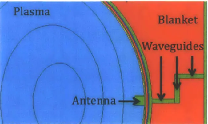
In conventional designs, the waveguides are placed at the outboard midplane and come straight into the device horizontally. This lets free-streaming neutrons through the waveguides in the vacuum region. In a reactor, this leads to unacceptable degradation of the superconducting toroidal field magnets at the outboard midplane. To mitigate this, the waveguides have to be installed with bends (or chevrons) so that they are not straight everywhere. One way to accomplish this is to bend them at right angles, as shown in Figure 3.1 below.
Plasma
BlanketWaveguidesl
j11
tN 1Antenna2.)l
Figure 3.1: Outboard midplane waveguide (shown in green) which is bent at right angles to prevent free-streaming neutrons from reaching the toroidal field magnets, and for the purposes of constructing the MCNP model, is comprised of three different sections.
In keeping with waveguides coming in to the vacuum vessel from the top of the tokamak, as in ARC, another configuration is to have the guides come straight down and then bend into place at an angle. This is shown below in Figure 3.2.
Figure 3.2. Alternative design for waveguide design for outer midplane launch (shown in green), in which they come from the top of the blanket tank and bend at an angle into the appropriate
location.
The second design used to obtain most of the results in the thesis, but a scenario with the first design was run to make a formal comparison. The comparison will be presented in Chapter 5. A
summary of all waveguide and antenna properties used for this study is given in Table 3.1.
Property Value
Waveguide/antenna structure material Inconel 718
Transmission coating Molybdenum
Density of structural material 4.1 g/cm'
Waveguide width 5 cm
Transmission coating thickness 1 mm
Transmission coating density 10.28 g/cm3
Total absorbed power in plasma 60 MW
Total surface area of antenna 4.8 m2
Antenna radial build 10 cm
3.3 MCNP models used for this thesis
The model of the ARC device was briefly described in Chapter 2. The two MCNP models used in this thesis are based heavily on the ARC model and are described in full detail in this section. The first "full" model includes every region in the ARC model, including insulation and the toroidal field magnets. The second reduced or "stripped" model, the one used for almost all tests, has the exact same dimensions as the first, but does not include anything radially beyond the blanket tank since the primary focus of this study is the effect on TBR and internal damage rates. In fact, an initial comparison between results from the full model and the stripped model revealed little differences for the DPA and helium production in the vacuum vessel as well as TBR in the cooling channel and blanket tank.
The original ARC model used a simplified elliptical vacuum vessel. This has been replaced in our new model with a more realistic D-shaped vacuum vessel, as shown in Figure 3.3 for the stripped model, which provides a tighter fit to the plasma shape.
--- First wall ooling channel
4 Beryllium
Figure 3.3. Stripped model with D-shaped vacuum vessel. Inset shows components of the vacuum vessel. Sky blue: plasma; orange: tungsten first wall and divertor at bottom of vessel;
Blanket


![Figure 2.2. MCNP model of the ARC reactor [1]. The plasma is shown in blue and is surrounded by a multi-component vacuum vessel, which is suspended by a support column shown in red.](https://thumb-eu.123doks.com/thumbv2/123doknet/14757237.583182/26.918.324.579.593.917/figure-reactor-plasma-surrounded-component-vacuum-suspended-support.webp)