Do Heavy Ions Induce the Bystander Effect?
Study to determine the induction of the bystander effect from Fe
ion beam compared to x-rays in human keratinocytes
by
Vered Anzenberg
Submitted to the Department of Nuclear Engineering in partial
the requirements for the degree of
Master of Science in Nuclear Engineering
at the
MASSACHUSETTS INSTITUTE OF TECHNOLO(
uep+eir 200u
August 2005
©(Massachusetts Institute of Technology 2005. All rights reserved.
/
Author ...
· D
Department of Nuclear Engineering
August 8, 2005
Certified
by...
-
l
....
Kathryn D. Held
Associate Professor, Harvard Medical School
Associate Radiation Biologist, Massachusetts General Hospital
Thesis Supe/sor
Read by ...
.'/4cquelyn C. Yanch
Professor of Nuclear Engineering, MIT
Thesis Reader
Accepted
by
...
-
--
f
.-....
Coderre...
Chaiman,
DpaJeffrey
Coderre
Chairman, Departmental Committee on Graduate Students
IDo Heavy Ions Induce the Bystander Effect?
Study to determine the induction of the bystander effect from Fe ion beam
compared to x-rays in human keratinocytes
by
Vered Anzenberg
Submitted to the Department of Nuclear Engineering on August 8, 2005 in partial fulfillment of the requirements for the degree of Master of Science in Nuclear
Engineering
Abstract
The bystander effect is the observation that non-irradiated cells near a cell traversed by
radiation express biological responses such as micronuclei formation and genomic instability. Most published studies of the bystander effect have been conducted using alpha particles, a high LET radiation. A few studies have been done with low LET radiation. This project studies the bystander effect from both low LET x-rays and high LET Fe particle beam irradiation. Using a transwell insert system, the bystander effect
was studied in hTERT immortalized human keratinocytes. Cells are plated in a 6-well plate and in a companion permeable membrane insert. Cells in the 6-well plate are
irradiated using conventional 250 kVp X-rays or 1000 MeV/nucleon Fe ion beam, LET of 151 keV/pm, from the NASA Space Radiation Laboratory at Brookhaven National
Lab. After irradiation, inserts are immediately placed into the 6 well plate so that the
irradiated and unirradiated cells are sharing medium but are not in contact. For both
beams, frequency of micronuclei, chromatin bridges, and p21 wafl induction as well as cell
cycle phase analysis were determined in both directly irradiated and bystander cells from
0.1 Gy to 5 Gy. From x-rays, a two-fold bystander effect at 24 h after irradiation with elevated p21 'wafl induction and micronuclei was seen but in Fe ion irradiation, the p21 wafl
bystander effect was delayed to 40-50 h after irradiation and no MN bystander effect was
observed. Cell cycle analysis showed a slight G2 arrest in keratinocytes 5 h after x-rays but a strong G2 arrest until 40-50 h was seen after Fe ion irradiation. Bystander
keratinocytes co-cultured with directly irradiated human fibroblasts AGO 1522 cells
showed a two-fold p21waft and MN bystander effect 24 h after x-rays, and a potential
2-fold MN bystander effect 50 h after Fe ions. Bystander AGO1522 cells co-cultured with
directly irradiated keratinocytes showed a two-fold MN bystander effect 24 h after x-rays, but no MN bystander response was seen at any time points studied from Fe ions. Striking differences in the bystander response were shown from the two radiation types,
but the reason remains to be clarified.
Thesis Supervisor: Kathryn D. Held
Title: Associate Professor, Harvard Medical School
Acknowledgments
I wish to give thanks to my co-workers at Massachusetts General Hospital for both the stimulating biology discussions and the non-biological ones as well. Thank you to the
support staff and scientists at Brookhaven National Laboratory, NASA Space Radiation Laboratory. Special thanks to Kamini Mahase for not only helping me with my
experiments but also for being a great friend.
Special thanks to Dr. Hongying Yang for her advice on experiments, great thought provoking discussions, constant support in my work and future endeavors and for the great comments on my master's thesis.
I would like to thank all the great mentors that I have had in the past years both at UC Berkeley and at MIT. Special thanks to Dr. Jacquelyn Yanch for being both a great
advisor and a strong supporter of my work. Deepest gratitude to Dr. Kathy Held for being an encouraging mentor and dedicated advisor. It has been a great honor to work in your
lab.
I would like to thank all my friends, both in the states and abroad, for the support and
friendship that I have been most blessed to have over the years. Most of all, I would like to thank my always-supporting family: my Dad, Mom, Alex, Eitan, and Paula. You have always allowed me to follow my dreams, and for that I am forever grateful.
This research was supported by National Aeronautical Space Administration grant # NAG-2-1642 and by the National Institute of Health Training grant to the Harvard
Contents
1 Introduction 10
1.1 Space Radiation Environment ... 12
1.1.1 Types of Radiation in Space ... 13
1.1.2 Risk from Space Radiation ... 14
1.1.3 Biological Effects of Space Radiation ... 15
1.2 Linear Energy Transfer (LET)...16
1.2.1 Relative Biological Effectiveness ... 18
1.3 Bystander Effect ... 20
1.3.1 Medium Mediated and Gap Junctions ... 21
1.3.2 Heavy Ions and the Bystander Effect ... 22
2 Methods and Materials 24 2.1 Materials ... 24
2.2 Cell Irradiation ... 25
2.3 Micronuclei and Chromatin Bridge Assay ... 28
2.4 p2 1 waf Immunofluorescence ... 29
2.5 Cell Cycle Assay ... 30
2.6 Colony Formation Assay ... 31
2.7 Statistical Analysis ... 31
3 Results 32 3.1 Cell Survival ... 32
3.2 p21wafl Expression ... 33
3.3 Cell Cycle Delays ... 36
3.4 Micronuclei Formation ... 41
4 Discussion 50
4.1 Effects on Directly Irradiated Cells ... 50
4.2 Effects on Bystander Cells ... 55
4.2.1 Keratinocytes to Keratinocytes ... 55
4.2.2 AGO 1522 cells to Keratinocytes ... 57
4.2.3 Keratinocytes to AGO 1522 cells ... 57
5 Conclusion 59 5.1 Future Work ... 61
List of Figures
2-1 Schematic of the transwell insert co-culture system ... 25 2-2 Bragg curve for 1 GeV/nucleon Fe ions. Horizontal axis is distance in water
traveled by a particle... 26
2-3 CCD camera picture of experimental setup for heavy ion irradiation.
Obtained with 1 GeV/nucleon Fe ion irradiation. Photograph shows 2 6-well plates held in place perpendicular to the beam by a plastic holder, shown as
dark outlines around the well plates ... 27
3-1 Survival Fraction of keratinocytes. Horizontal axis is dose (Gy). X-ray data
(A) are the means of three independent experiments + s.e and fit with the curve SF = exp (-0.276D -0.0587D2). Fe ion data () are from one experiment and fit with the curve SF = exp (-1.44D) ... 32
3-2 In situ immunofluorescence detection of p21wafl in keratinocytes 24 h after x-ray irradiation. (a) unirradiated cells; (b) cells directly irradiated with
2 Gy x-rays... 33
3-3 In situ immunofluorescence detection of p21wafl in bystander keratinocytes 24 h after x-ray irradiation. (a) cells co-cultured with unirradiated cells; (b)
bystander cells co-cultured with cells irradiated with 2 Gy x-rays ... 34
3-4 Dose response for induction of p21wafn in directly irradiated and bystander keratinocyte cells 24 h after x-ray irradiation. Results are the means of at
3-5 Dose response for induction of p21wafl in directly irradiated and bystander
keratinocyte cells 40-50 h after Fe ion irradiation. Results are the means of at least three independent experiments ± s.e ... 35
3-6 Dose response for induction of p21w afl in bystander keratinocyte cells co-cultured with AGO1522 cells for 24 h after x-ray irradiation. Data are averages
of two experiments and error bars represent the range ... 36
3-7 Cell cycle distribution in directly irradiated keratinocyte cells 5 h after x-ray
irradiation. Data are based on one experiment ... 37
3-8 Cell cycle distribution in directly irradiated keratinocyte cells 24 h after x-ray irradiation. Data are the averages of two experiments ± range ... 38 3-9 Cell cycle distribution in directly irradiated keratinocyte cells 48 h after x-ray
irradiation. Data are the averages of two experiments ± range ... 38
3-10 Cell cycle distribution in directly irradiated keratinocyte cells 5h after Fe ion
irradiation. Data are the means of at least three experiments ± s.e ... 39
3-11 Cell cycle distribution in directly irradiated keratinocyte cells 24h after Fe ion irradiation. Data are the means of at least three experiments ± s.e ... 39
3-12 Cell cycle distribution in directly irradiated keratinocyte cells 40h after Fe ion irradiation. Data are the means of at least three experiments ± s.e ... 40
3-13 Cell cycle distribution in directly irradiated keratinocyte cells 50h after Fe ion
irradiation. Data are the means of at least three experiments ± s.e ... 40
3-14 In situ fluorescence detection of micronuclei in directly irradiated keratinocyte
3-15 Comparison of dose response curves for induction of MN in keratinocytes after x-rays with and without cytochalasin B. Samples with cytochalasin B were fixed 72 h after irradiation. Samples without cytochalasin B were fixed at 24 h.
Data shown are based on one experiment for cytochalasin B ... 42
3-16 Dose response for induction of micronuclei from directly irradiated and bystander keratinocyte cells 24 h after x-ray irradiation. Data are the means of at least three experiments ± s.e ... 43 3-17 Dose response for induction of micronuclei from directly irradiated
keratinocyte cells 24, 48, and 72 h after Fe ion irradiation. Data are the means of at least three experiments ± s.e ... 44
3-18 Dose response for induction of MN in bystander keratinocyte cells co-cultured with directly irradiated AGO1522 cells for 24 h after x-rays. Data are the means of at least three experiments ± s.e ... 46 3-19 Dose response for induction of MN in bystander AGO1522 cells co-cultured
with directly irradiated keratinocyte cells for 24 h after x-rays. Data are the means of at least three experiments ± s.e ... 46
3-20 In situ fluorescence detection of chromatin bridges in directly irradiated keratinocytes 48 h after 3 Gy of Fe ions. Data are the means of at least three experiments ± s.e ... 48 3-21 Dose response for induction of chromatin bridges in directly irradiated
keratinocyte cells 24 h after x-ray irradiation. Data are the means of at least three experiments ± s.e ... 49
3-22 Dose response for induction of chromatin bridges in directly irradiated keratinocyte cells 24, 48, and 72 h after Fe ion irradiation. Data are the means
List of Tables
3.1 Dose response for induction of MN in keratinocyte bystander cells co-cultured
with directly irradiated keratinocyte cells from Fe ion irradiation. (a) 24 h;
(b) 48 h; (c) 72 h after irradiation ... 45
3.2 Co-cultured bystander samples from Fe ion irradiation. (a) Bystander response
in keratinocytes co-cultured with directly irradiated AGO 1522 cells for 50 h after Fe
ion irradiation. (b) Bystander response in AGO 1522 cells co-cultured with directly
Chapter 1
Introduction
Radiation dosimetry is the branch of nuclear science that quantifies the changes in a chemical and/or biological target due to radiation. When radiation interacts with a human cell, it deposits energy within the cell, which produces excited and ionized atoms. The linear energy transfer, LET, characterizes the amount of energy that is deposited within the cell per unit distance along the charged particle track. This energy can create
chemically active species or directly damage the DNA helix, which ultimately can either cause cell death, or if the DNA is inappropriately repaired, a possibility of neoplastic transformation, which may lead to cancer. Therefore, it is important to characterize the exposure of radiation, or the dose, that an individual is receiving in order to assess the possible biological damage.
The estimates used for cell damage are currently based on the theory that a cell is
damaged only if radiation traversed the cell. However, in the past decade, there has been evidence by several independent research groups that indicates higher damage within cell cultures than expected based on the number of cells traversed by the radiation, and the term bystander effect has been coined to describe the response (Nagasawa and Little
1999; Mothersill and Seymour 2001; Yang et al. 2005). The bystander effect is the
responses such as micronuclei formation (MN), genomic instability and cell cycle related
gene expression induction (Azzam et al. 1998; Nagasawa and Little 1999). Several research groups have concluded that some signal is being transferred from the irradiated cells to the non-irradiated cells, which is also causing DNA damage in the non-irradiated cells.
Astronauts during space flight are exposed to radiation backgrounds composed of trapped proton and electron radiation, galactic cosmic rays made up of energetic protons and heavy ions, and sun radiation. The high LET components of the galactic cosmic rays, the heavy ions and energetic protons compose approximately 10-30% of the dose on a shuttle mission (Wilson 2000). Current carcinogenesis risks for low LET radiation are determined by linear back extrapolation from data at high doses of low LET radiation (x-rays and gamma (x-rays). Carcinogenesis risks for high LET radiation are determined by making assumptions of greater biological damage than from low LET radiation. Previous
experimental results have shown an increase in cell death due to the bystander effect from
low LET radiation and alpha particles, but there has been little study of the bystander effect with heavy ion radiation as found in space. National Aeronautics and Space Administration, NASA, is specifically concerned with the possible increase in biological effects from exposure to space radiation environments and the biological effects from energetic protons and high LET radiation on the molecular level. Therefore, it is important to study the bystander effect for a broader range of radiation qualities, more specifically fr heavy ions and highly energetic protons as encountered by astronauts, and compare it to the bystander effect seen with low LET radiation. The goal of this project is to study the induction of the bystander effect by heavy ions, such as Fe ions, and compare
the bystander results to those obtained with conventional x-rays. This project seeks to develop and answer three aims:
1. Determine the occurrence of bystander effect(s) from conventional x-rays in a cultured keratinocyte cell line. Dose response curves will be obtained for the induction of the bystander effect.
2. Determine the occurrence of bystander effect(s) from Fe ions at the NASA Space Radiation Lab at Brookhaven National Laboratory. Dose response curves will be
obtained for the induction of the bystander effect for the same biological endpoints as for the conventional x-rays. Compare results from Fe ions to those of x-rays. (Low and high LET comparison)
3. Determine the induction of the bystander effect(s) from Fe ions and conventional
x-rays from human fibroblasts co-cultured with keratinocytes and vice versa.
1.1 Space Radiation Environment
NASA's current plan for future missions includes a potential manned mission to Mars, long-term missions to the lunar surface, and the International Space Station (ISS).
Earth's magnetic field shields equipment and people from a large portion of the radiation in earth's orbit but outside the earth's field, the radiation environment is drastically different. Two keys points must then be considered: shielding astronauts from the radiation environment, and determining biological effects from the types of radiation in
space.
Earth's atmosphere is an equivalent of 10 m of water and shields cosmic ray
levels on earth to give an annual background dose of 0.27 mSv, which is only 8% of our
reside on the ISS for 4-6 months is estimated to receive an approximate dose of between 8-20 cSv, a 30 fold increase over annual background dose rates on earth (Cucinotta
2000). More importantly, an astronaut is going to receive more fractioned and higher dose rates of exposure 24 h each day, unlike any other occupational exposures (Cucinotta 2000; Wilson 2000). In addition, occupational limits to NASA astronauts are higher than
any other terrestrial radiation workers. When looking at risk assessment for space travel, the types of radiation must be considered.
1.1.1 Types of Radiation in Space
There are three main types of radiation in space: galactic cosmic rays (GCR), earth's radiation belts (van Allen radiation belts), and solar particle events. The energies and types of the particles will vary greatly due to the shielding from the spacecraft. However,
the radiation environment will be due to both the primary particles as well as any
secondary particles that could be formed.
Galactic cosmic rays are largely highly energetic protons and heavier ions, with a
2% component of electrons and positrons. Abundances of heavy ions decrease as atomic number increases, but peak again at iron. GCR are emitted isotropically in space, have roughly constant fluence, and have a broad energy spectrum, peaking at about 1
GeV/nucleon. The source of GCR is unknown, but outside our solar system. Solar events
can change and influence the GCR fluence. It is estimated that 10-30% of whole body dose on shuttle missions is due to GCR (Wilson 2000).
The second type of radiation in space is from charged particles trapped in the van Allen radiation belts in a magnetic field surrounding the earth. The inner belt is mostly
10 MeV. These belts are a problem for space travel when a spaceship passes through them and can be an issue for both the electronics and for the astronauts.
The third type of radiation occurs from solar particle events (SPEs) from the sun. The sun produces a constant flux of predominately low energy protons. However when a
magnetic storm occurs on the sun, this can cause solar flares of increased radiation.
Strong space weather with lethal doses occurring over very short periods of time has also
been recorded. The majority of SPEs are high-energy protons and can create a
noteworthy radiation risk to astronauts. Monitoring for SPEs occurs on the spacecraft,
and "storm shelters" have been built for protection for the astronauts. A round trip to Mars is projected to take 3 years. An SPE event is probably likely within that time period. More importantly the risk from SPEs comes when an astronaut is out of the shuttle or on the lunar or Martian surface.
1.1.2 Risk from Space Radiation
Risk estimation based on experimental measurement for the radiation in space is nearly non-existent. Some high-energy protons are known to have a biological effectiveness
value close to 1. Even though only about 10-30% of the space radiation fluence is the
high-energy high Z particles (HZE), these represent the greatest risk. The quality factor associated for missions dominated with GCR radiation is currently set at 2.5 (Cucinotta
2000; Wilson 2000). However, the main concern for NASA is due to the long-term
missions such as on ISS or Mars where the current projections of risk models for late effects from heavy ions and neutrons are not so dependable (Cucinotta 2000).
Space radiation is predominately low fluences of high LET radiation with rates at
and 0.04 HZE particles/ cm2 sec with energies of a few hundred MeV to several GeV/ nucleon (Curtis and Letaw 1989). For a typical cell nucleus of 100 jim2, each cell nucleus in the body would receive a proton every 3 days, helium once a month, and a HZE
particle (high atomic number and energy) once per year (Curtis and Letaw 1989). With
such low fluences, the real risk is from late effects from space travel. Current risk
assessment is done with knowledge of high doses, from 0.5 -2 Gy, that were delivered as one single shot at high dose rates of low LET radiation. Risk in the low dose region is then determined by linear back extrapolation to low doses and assumptions are made to correct for low dose rates and for high LET (BEIRVII 2005). At doses below 1 Gy, risk estimation offers three models: linear no threshold, threshold and linear quadratic. The choice of model will affect greatly the radiation protection and associated risk. The critical issue for NASA regarding risk assessment is the fact that the radiation environment in space is a continuous flux of low doses from both low LET and high LET. Furthermore, the radiation environment is a mixed radiation field. This field is much different from that used as the basis for the current risk assessment models. Therefore it is crucial for NASA to have a basic understanding of the radiobiology involved with the types of radiation encountered in space and to develop accurate and precise radiation risk models for space travel. Currently there is an insufficient amount of data on HZE particles regarding biological effects to allow fully informed risk
assessment.
1.1.3 Biological Effects of Space Radiation
(Turner 1995). However biological differences will occur based on the radiation quality. The long-term biological effect that NASA is most interested in is cancer, a
non-deterministic effect. More importantly, NASA puts a limit on the radiation risk to an astronaut from career radiation exposure of a 3% excess risk of cancer fatality (Cucinotta 2000). The basic question that NASA wants answered is what is the unique biological effect due to HZE particles of low fluence. Current preliminary research has shown that HZE particles lead to behavioral effects such as motor performance, premature aging, genomic instability, clustered DNA damage, cell cycle delays, cataracts and central
nervous system damage (Worgul et al. 1989; Scholz et al. 1994; Goodhead 1995; Tsuboi et al. 1998; Blakely 2000; Shukitt-Hale et al. 2000; Smith et al. 2003). Due to the low
fluence environment in space, the additional biological responses from non-targeted cells
such as the bystander effect may prove to be important in the overall radiation risk
assessment.
1.2 Linear Energy Transfer (LET)
As a heavy charged particle travels through matter it will deposit its energy largely by excitations anrid ionizations of atoms. Typically, a heavy charged particle will lose a small amount of its energy with a single electron collision, and therefore the path will be almost straight with only slight deflections. Unlike heavy charged particles, electrons and
positrons will impart a large portion of their energy in a single electronic collision and
will therefore have very torturous paths with great deflections. Additionally, both light and heavy charged particles can impart enough energy to oust an electron from the target
material and that electron has enough energy to have its own path. These electrons are
with a track length of 800 gm, a large distance compared to a typical size of a cell of 10
pm (Chatterjee and Schaefer 1976).
To quantify the average linear energy loss of a charged particle in a medium over a given length, or in other words, the average ionization density along the direction of travel, the term linear energy transfer, LET, was coined. It describes the energy absorbed in the target in units of keV jim'. However it is important to note that when speaking of energy loss, it is not a continuous slowing down, but instead a discrete process and that LET only quantifies the average slowing down value. Also, the peak energy loss will
occur at the end of the particle track, or range, as the particle is slowing down and
picking up charge. For example, a 290 MeV/ nucleon carbon ion will have an LET of
13.6 keV/ Em, a 1 GeV proton will have an LET of 0.223 keV/ gm, and a 1 GeV/ nucleon
iron ion will have an LET of 151 keV/ gm. In contrast, a 250-kVp x-ray beam will have
an LET of 2 keV/ gm, based not on the x-ray beam since it is not charged but on the secondary particles that are formed. In this case, the x-rays or protons will be considered
low LET, the carbon is medium LET, and the iron is considered a high LET ion. Again,
these are averages on the macroscopic level. On the microscopic level, the energy deposited per unit length varies significantly over the track length.
Track structure depends greatly on LET. A high LET ion such as an iron ion of 1 GeV/ nucleon will have a thicker and shorter particle track compared to that of a low LET proton ion of the same energy. Fewer particles of high LET would be needed to give the same dose of 1 Gy compared to a low LET particle because the high LET particle will deposit this energy in a much shorter distance and has a dense formation of reactants
by these particles is not considered in the calculation of LET. However, delta rays are of low LET and as mentioned, have a torturous track path. Therefore, in reality, a heavy ion will have combined high LET and low LET components to its track.
1.2.1 Relative Biological Effectiveness
Relatively little has been determined regarding biological effectiveness of high LET radiation, partially due to the fact that ions of high LET other than alphas must often be produced in accelerators and are not as available as conventional x-rays. However, a few things are well established. For cell survival curves, for low LET radiation, a repair
shoulder is visible in the low dose region but for high LET radiation, the survival curve is a straight line, with no repair region (Hall 2000). This is stating that high LET radiation is more effective at causing cell death than low LET radiation and that at the low doses no
repair is seen. It has also been shown that high LET radiation is more effective at
mutagenesis and chromosome aberrations compared to low LET radiation (Ritter et al. 1992; Masumura et al. 2002). Other findings include induction of more complex
clustered lesions at high LET radiation (Sutherland et al. 2001). This is based on the fact
that high LET radiation interacts with DNA directly compared to indirectly for low LET. When speaking of risk from high LET radiation, the relative biological
effectiveness (RBE) ratio is used. It is a ratio between the dose of the low LET radiation, i.e. x-rays, compared to the dose needed of high LET radiation that would give the same
biological effect. RBE is dependent on LET, dose rate, dose fractionation, and the
associated with heavy ion particles or, simply, high LET radiation is more effective at biological damage that is less repairable than low LET radiation.
In addition to looking at risk through the RBE, quality factors have also been set for different radiation types. High LET radiation is known to be more effective at
damaging a biological system per unit dose, and to quantify the effectiveness of different radiation types the International Committee on Radiological Protection (ICRP) have
incorporated the quality factor, Q. The Q value is essentially like an RBE, where it takes
into consideration the effectiveness at producing biological damage from different types of radiation. Also, the commission introduced the dose equivalent value that incorporates different radiation qualities by multiplying the dose in Gy by Q and ending in units of Sv.
The Q value is dependent on LET, where the Q value for x-rays is 1 but for a heavy ion
of LET such as iron, the Q value is between 10-20 (Turner 1995). Dose equivalent has been a measure for radiation protection and radiation limits are set for occupational workers using it. However, knowledge of the biological effects of high LET radiation is limited due to the lack of high LET radiation facilities on earth, and therefore the models used for Q values of high LET are in constant debate and in need of additional support from traditional biology. More specifically, for NASA the uncertainties related to space radiation and related biological effects raises difficulties in determining Q values and radiation risks associated with the high LET components of space. Several issues then
arise. In space, radiation is present in low fluences but all the time and is a combination of all types. How does one assign a Q value or a radiation risk to a small population of
cells receiving low doses of different radiations? When speaking of dose in space, one
microscopic level the dose is significant to a small portion of the population. More so,
with the possibility of the bystander effect contributing potentially additional damage to cells not traversed by radiation, radiation risk and models will need to be reevaluated for
space travel.
1.3 Bystander Effect
Traditional cell damage is currently based on the theory that a cell is damaged only if radiation traverses the cell. Damage to the DNA can include base damage, single strand breaks, double strand breaks, and crosslinks within the DNA. Also, damage to the cell can be shown through activation of specific proteins, serious chromosomal damage such as micronuclei formation or chromatin bridges, cell cycle arrest, or cell death via
apoptosis or necrosis when damage cannot be repaired. It has been traditionally thought
that damage must occur to the nuclear DNA in order to have cell damage. However, in
the past decade, there has been evidence by several independent research groups that indicates higher damage within cell cultures than expected based on the number of cells traversed by the radiation, and the term-bystander effect has been coined (Mothersill and
Seymour 1997; Nagasawa and Little 1999; Lyng et al. 2000). The bystander effect is the
observation that non-irradiated cells near a cell traversed by radiation also express biological responses such as double strand breaks, micronuclei, genomic instability, and cell cycle arrest. The bystander effect was first shown by Nagasawa and Little when they irradiated only 1% of the cell population with a-particles but saw chromosome damage via sister chromatid exchanges in up to 30% of the cell population (Nagasawa and Little
1992). Since then, other instances of the bystander effect have been characterized using the medium transfer method, gap junction dependency, or microbeams.
1.3.1 Medium Mediated and Gap Junctions
Mothersill and Seymour et al. showed that by transferring medium from low LET
irradiated cells to non-irradiated cells, the non- irradiated cells had an increase in cellular
damage (Mothersill and Seymour 2001). They concluded that some factor is being transferred from the irradiated cells into the medium, which is causing an effect in the non-irradiated cells. Another instance of medium mediated bystander effect has been
shown using the insert system (Yang et al. 2005). Unirradiated bystander cells were
shown to have an increased induction of micronuclei when sharing medium with cells that were irradiated with 250 kVp x-rays.
Another experiment done by Mothersill and Seymour et al. looked at the role of cell-cell contact. Connexin proteins, which make up the gap junctions, pass ions, second messengers and small metabolites between cells that are in contact such as confluent
cells. The experiment was performed using a GJIC (gap junction intercellular
communication) inhibitor. They showed that by inhibiting the gap junctions, the
bystander effect did not decrease (Mothersill and Seymour 1998). Contrary to the data of Mothersill and Seymour, Azzam and Little et al. showed that inhibition of gap junctions
in their cell line did decrease the bystander effect (Azzam et al. 1998). Since gap
junctions are too small to pass proteins, it has been hypothesized that perhaps the bystander effect is an emission of reactive species into the medium. Although the exact
nature of the bystander effect is unknown, it has been shown that in some cell lines, it is
contact and is medium mediated. Also it has been shown that by targeting only the cytoplasm of radioresistant glioma cells using a microbeam, a bystander effect was seen
(Wu et al. 1999; Shao et al. 2004). One important characteristic of the bystander effect is that there is no threshold at which the bystander effect starts. It appears to be present at
the lowest doses tested (Ballarini et al. 2002). The bystander effect is most likely a combination of various factors, dependent on cell type and intercellular communication. It has been shown to be dependent on reactive oxygen species such as hydrogen peroxide and superoxide, cytokines, transforming growth factor 31, or perhaps a combination of
the above (Lyng et al. 2000).
There is a debate as to whether the bystander effect is a biological defense mechanism or an enhancement of cell death. A commonality from all the bystander
effects that have been recorded is the fact that most responses are evident at low doses
and saturate after 0.5 Gy. If the damaged cells release a factor into the medium, perhaps it
is to enhance cell killing in order to protect against the possibility of carcinogenic damage due to the surrounding radiation changes. Another possibility is that this is a negative effect, and that critical cells are killed. Regardless of whether the bystander effect is a positive or negative mechanism, it is occurring and detailed studies of the mechanisms
involved are needed.
1.3.2 Heavy Ions and Bystander Effect
Currently little is known regarding biological effects from high doses of heavy ions, let
alone to be able to understand risks from low doses. To date, little work has been done
bystander efifect by Shao et al. with carbon ions. The group showed a micronuclei bystander response after 13 keV/jtm and 100 keV/itm carbon ions in human salivary gland neoplastic cells (Shao et al. 2002). Additionally, they showed that with the addition of a NO scavenger, PTIO, the bystander effect was eliminated after 100 keV/gm carbon
ions in these cells. The group also looked at the role of gap junctions in human
fibroblasts AGO1522 after a 290 MeV/nucleon carbon ion beam of LET 100 keV/jtm
(Shao et al. 2003) (Shao et al. 2003). They grew AGO1522 cells to confluency and
inhibited gap junctions with lindane and found the MN bystander effect decreased considerably but not completely. Similarly, they added cAMP, which is an enhancer of
GJIC and saw somewhat of an increase of the low dose bystander response.
The purpose of this project is to characterize the induction of the bystander effect
from heavy ions, specifically iron, as will be encountered in space. Comparison of
biological responses after low LET 250 kVp x-rays will be made with the 1 GeV/nucleon iron ions of high LET. Endpoints that were explored included micronuclei formation,
chromatin bridges, p21 waf expression, and cell cycle changes in human keratinocyte
cells. Also, data will be presented that show the induction of the bystander effect
signaling from two different cell lines, fibroblasts and keratinocytes, from both beams in
the form of micronuclei and p21 wafl induction. The reasoning behind mixing cell lines is
the eventual movement to studies of bystander induction in tissues composed of these
two cell lines, a more in vivo approach. All bystander induction is represented as a form
Chapter 2
Materials and Methods
2.1 Materials
The two cell lines used are the hTERT immortalized keratinocytes (Dickson et al. 2000) and the AGO 1522 normal human skin diploid fibroblasts which were obtained from Genetic Cell Respository at the Coriell Institute for Medical Research (Camden, NJ,
USA). Both cell lines have wild-type p53. The keratinocytes were grown in 37°C in 95%
air and 5% CO2with Keratinocyte-SFM (Gibco) supplemented with 100 U/ml penicillin,
0.1% of 0.3 mM CaCL2, L-glutamine, epidermal growth factor, and bovine pituitary extract. AGO1522 cells were grown in 37°C in 95% air and 5% CO2 with at-modified
MEM (Sigma) supplemented with 20% fetal bovine serum (FBS, Hyclone), 100 ~tg/ml
streptomycin and 100 U/ml penicillin. When the AGO1522 cells were used during experiments, the medium was changed to the keratinocyte medium. All AGO 1522 experiments were initiated by the addition of Trypsin and re-plating confluent cells at numbers of 5x10⁴-1.3x 10⁵, depending on the time of assay. Keratinocytes differentiate once confluent and therefore were kept at low cell densities to ensure that by the time of assay cells had not grown to confluency. Therefore all plating with keratinocytes was
irradiation. For studies at Brookhaven National Laboratory, cells were transported and
given at least 1 day in the incubator to restabilize the pH and temperature prior to plating
for heavy ion beam irradiation.
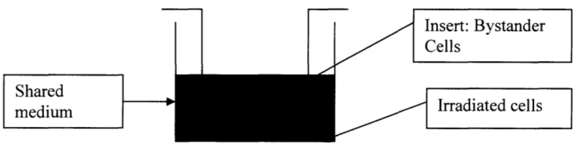
The bystander studies were performed in an insert system as shown below in Figure 2-1. Cells were plated in wells of a 6 well dish (Falcon) with growth area of 9.6 cm2per well and a companion transwell culture dish (Falcon) with a growth area of 4.2
cm2. The inserts have a membrane with pores of 1.0 pm at a density of 1.6x 10⁶/cm2to
allow passage of molecules. Using this system, cells plated in the dish are those that are irradiated and immediately after irradiation inserts were placed into the wells, serving as the bystander cells. Therefore, medium passed between bystander and directly irradiated cells, but a distance of 0.9mm separated the cells.
Insert: Bystander Cells
Shared
medium Irradiated cells
Figure 2-1: Schematic of the transwell insert co-culture system.
2.2 Cell Irradiation
Prior to irradiation, fresh medium was added to each well and insert only for x-rays. Due to the setup for the iron beam, all media was aspirated prior to irradiation. Irradiations were performed at room temperature using a 250 kVp X-ray machine (Siemens
GeV/nucleon Fe beam of LET of 151 keV/p.m irradiations were performed at the NASA Space Radiation Laboratory (NSRL) located in Brookhaven National Laboratory, Upton,
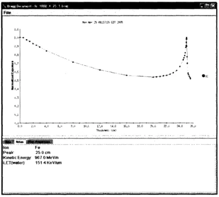
NY with dose rates ranging from 0.05 Gy/min to 2 Gy/min. The Bragg curve for 1
GeV/nucleon was obtained from Dr. Adam Rusek, physicist at NSRL, and is shown in Figure 2-2. The Bragg curve is obtained through a thickness in plastic of equivalent
density of tissue.
Figure 2-2: Bragg curve for 1 GeV/nucleon Fe ions. Horizontal axis is distance in water
traveled by a particle.
Since the Fe ion beam traveled through mostly air and a little bit of the plastic of the
wells, the irradiation is performed over the beginning of the Bragg curve where it is linear
over that region and little loss in energy or LET occurs through the sample. Figure 2-3 shows the holder, darker edges, and the wells on a CCD camera picture taken during
irradiation with 1 GeV/nucleon Fe ions. The beam comes perpendicular, out of the page.
P -5 .17.'4 ET 22 1.1 .1,2 0. 05 °'~~~~~~~~~~~ht ... .C . .t lp '4. ((. O ) . 22.2 : 24.0 AC.. i ? .. . .. A~~~~~~~~~~~~~~~~~~~~~~~~~~~~~~~~~.. ... .. .. ... .. . .-. . !ion Fe Peak 25 0 cm
Kinetic Enortg' 96.0 MeV/n
LET(water)' 151 4 KeVlumn
... .... .... ... .... .... .... ... .... .... .... ... .... ... ... .... .... .... ... .... .... .... ..-. .... .... ... .... .... .... ... .... .... .... ... .... .... ... .... .... .... ... .... .... .... .... .... .... ... ... .... .... ... .... .... ....
---
---Mai" 5 --
_ . .Figure 2-3: C(CD camera picture of experimental setup for heavy ion irradiation. Obtained with 1 GeV/nucleon Fe ion irradiation. Photograph shows 2 6-well plates held in place perpendicular to the beam by a plastic holder, shown as dark outlines around the well plates.
At NSRL, dose is calculated using ionization chambers. Ionization chambers essentially
are two parallel plates in a gas filled chamber attached to a voltage source. When
radiation passes through the gas chamber, it ionizes the gas and the particles travel to the
plates and create a voltage drop, which is recorded (Knoll 1999). Ionizing chambers are used to count the number of particles that pass through the chamber, hence the fluence of
the beam. To calculate dose in air, the simple expression can be used:
dE 2-1
pdx)
where the dose rate is equal to the fluence rate times the stopping power divided by the
density of the material. The ionization chamber gives the fluence rate. The difference
between requested dose and delivered dose for the Fe ion beam never exceeded 2% and
Immediately after irradiation, inserts were placed in the wells and cells were
co-cultured together in the incubator until time of fixation. Controls were also treated in the same manner, without irradiation. All bystander samples were done in the 6 well plate and insert system, but cell cycle analysis was done in cells in T75 flasks.
2.3 Micronuclei and Chromatin Bridge Assay
A micronucleus is a chromosome fragment that is not included with the rest of the
nucleus at cell division. It has enough information to form its own nuclear membrane and looks like a mini nucleus in the cytoplasm. The rate of micronuclei (MN) formation after
both types of irradiations was determined by two methods. The first was using the cytokinesis-block technique(Fenech and Morley 1986). After placing inserts into the
companion wells, cytochalasin B (Sigma) was added to the co-culture to a final
concentration of 0.5 g/ml. After 72 h, cells were fixed in methanol:acetic acid (3:1 v/v).
After allowing the samples to dry, cells were stained with the nuclear stain 4',
6'-diamidimo-2-phenylindole (DAPI) solution (10 ptg/ml in water). Cells then were mounted with FluoroGuardTM Antifade reagent (Bio-rad) to preserve the fluorescence stain.
Micronuclei were scored under a fluorescence microscope in only binucleated cells. At
least 500 cells were scored from at least 10 view fields. In the second method no cytochalasin B was added and cells were fixed 24 h after irradiation. The staining and
counting procedure remained the same. For the AGO 1522/Keratinocyte and vice versa bystander co-culture samples, cytochalasin B was not used due to toxicity issues arising from concentration differences of the chemical for the two cell lines. Instead samples
Another type of chromosomal damage that became apparent in the keratinocytes
is chromatin bridges. During cell division, the duplicated DNA in the cell is condensed to
identical copies of chromosomes. In mitosis, the phase when the chromosomes get
separated and are pulled apart is known as anaphase. Usually, each chromosome is pulled apart by equal force and each daughter nucleus gets the identical chromosomes.
However, it has been shown that from various toxins such as cigarette smoke, UV light,
and radiation, during anaphase, while the two chromosomes are being pulled apart, instead the chromosomes continue to fuse together forming a chromatin bridge between
the two daughter cells (Gisselsson et al. 2000; Thomas et al. 2003). The final appearance
has two separated nuclei with a string of various lengths and thickness of chromatin connecting them together. Chromatin bridges were counted using the same procedure
outlined above for micronuclei without cytochalasin B. Cells were fixed 24 hours after irradiation and stained with DAPI.
2.4 p2 1Wafl Immunofluorescence
It has been well documented that after UV or ionizing radiation, cells with wild-type p53
respond by increasing p53 levels which in turn arrests the cells until damage is repaired or triggers the cells to programmed cell death called apoptosis (Concin et al. 2003). p2 1wafl is a direct downstream response protein of p53 that is involved in cell cycle arrest.
Therefore, p21 wafl induction is an indication that p53 was activated.
Immunofluorescent staining as summarized here is previously described by Azzam et al., 2001 and was analyzed at various time points after irradiation for the iron
determined as the peak response of p21 waf after a 2 Gy irradiation with x-rays by a time course curve (data not shown). At the time of staining, cells were rinsed in PBS
supplemented with 1 mM MgCl2 and 0.1 mM CaCl2 (PBS+), then fixed in 3% (v/v)
paraformaldehyde in PBS+ for 30 minutes. After a 5 minute rinse with 50 mM NH4C1
and two rinses with PBS+, the cells were permeabilized in ice cold Triton X buffer
consisting of 50 mM NaCl, 3 mM MgCl2, 200 mM sucrose, 10 mM HEPES, pH 7.4, and
0.5% Triton - 100 in water. After three rinses with PBS, cells were blocked in 10% goat serum for 20 min and then incubated in p21 waf, mouse monoclonal antibody (Oncogene) for 1 h and then stained with Alexa 488 goat anti-mouse IgG secondary antibody
(Molecular Probes) for 45 min at room temperature. Cells were then washed at least twice with PBS before staining with DAPI (Sigma) for 2 minutes and followed by two washes with PBS. Cells were mounted with FluoroGuardTM Antifade reagent (Bio-rad) to preserve the fluorescence stain. At least 500 cells were counted from at least 10 fields of views.
2.4 Cell Cycle Assay
Cells go through a cell cycle consisting of four phases: G1, S, G2 and mitosis. It has been
well documented that if cells are damaged via radiation, the cells will arrest in G1 via p53
or G2 and will not proceed through the cell cycle until damage is repaired. If damage is not repaired, cells will go into apoptosis, necrosis or permanent cell cycle arrest.
Cell cycle analysis was performed on directly irradiated keratinocytes to compare cycle delays from x-rays and iron ions. Cells were seeded 24 hours prior to irradiation in
T75 flasks with cell densities that would ensure at least 2x 10⁶ cells on the day of
irradiation for x-rays and 5, 24, 40, and 50 h post iron irradiation. At the time of
processing, cells were trypsinized, collected, and washed twice with PBS. Cells were then
vortexed to maintain single cell suspension and fixed in 100% ice-cold ethanol at least
overnight. Cells were then rinsed again in PBS and stained with 0.5 mg/ml RNase
(Sigma), 0.1 mg/ml Propidium Iodide (PI) (Sigma), 0.1% NP40 (Sigma) detergent in PBS for a total of 0.5 ml working volume. Cells were then analyzed for DNA content using the flow cytometer FACScalibur (Becton Dickson, Franklin Lake, NJ USA) with the
software CellQuest V5.1 Mac OS X.
2.5 Colony Formation Assay
Clonogenic assay was performed to obtain survival curves for directly irradiated keratinocytes. Cells were plated in T25 flasks at 300 cells/flask for x-ray doses of 0-0.5
Gy, 450 cells/flask for 1 Gy, 600 cells/flask for 2 Gy, and 3000 cells/flask for 3 Gy and 5
Gy. After 24 hours, cells were irradiated with x-rays and then incubated for 10-12 days. Colonies were fixed in methanol and stained with methylene blue. Colonies containing at least 50 cells were counted. For x-rays, the linear-quadratic model with the equation SF=exp(-aD-3D2) and for the Fe ion beam the linear equation SF=exp(-aD) was used
where D is dose in Gy, and a and f3 are constants.
2.6 Statistical Analysis
All data shown here are from at least three or more separate experiments, unless otherwise noted. All results are recorded as means + standard error. Statistical comparison of the groups and controls was done using SigmaPlot 2001 software.
Chapter 3
Results
3.1 Cell Survival
To see the relative biological effectiveness between 250 kVp x-rays to 1000
MeV/nucleon Fe ion beam, standard survival curves were obtained and are shown in
Figure 3-1.
Dose (Gy)
O01
01
Figure 3-1. Survival Fraction of keratinocytes. Horizontal axis is dose (Gy). X-ray data
(A) are the means of three independent experiments ± s.e and fit with the curve
SF = exp (-0.276D -0.0587D2). Fe ion data () are from one experiment and fit with the curve SF = exp (-1.44D).
The iron curve is based only on one experiment and therefore has no error bars. The x-ray
curve showed a typical repair shoulder, whereas the Fe curve showed a steep linear decrease, as usually noted with low and high LET radiations. For iron, the equation that
characterizes the curve is SF = exp (1.44D) and for the xrays SF = exp (0.276D -0.0587D2).
3.2 p21Wafl Expression
Expression of the protein p2 lwaf in keratinocytes was determined both in directly
irradiated cells and bystander cells. In Figure 3-2, p2 1 wafl induction is seen using a
fluorescent labeled antibody in keratinocyte cells and compared visually between control
and directly irradiated cells 24 h after 2 Gy of 250 kVp x-rays. Figure 3-3 shows the 24 h
p21 waft induction in bystander keratinocyte cells co-cultured with control and directly irradiated keratinocyte cells with 2 Gy x-rays. All of the samples shown were stained at the same time and under the same conditions.
Figure 3-2: In situ immunofluorescence detection of p2l 'an in keratinocytes 24 h
after ray irradiation. (a) unirradiated cells; (b) cells directly irradiated with 2 Gy
Figure 3-3: In situ immunofluorescence detection of p21Wafl in bystander
keratinocytes 24 h after x-ray irradiation. (a) cells co-cultured with unirradiated cells;
(b) bystander cells co-cultured with cells irradiated with 2 Gy x-rays.
Keratinocytes were fixed 24 hours after x-ray irradiation because this was found to be the time of maximum p21 wafl induction in keratinocytes from a time course. However it was
seen that from iron irradiation, p21 wafl expression did not appear until 40-50 h after irradiation, showing at least a 24 h delay compared to x-rays. Figure 3-4 shows induction
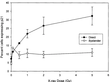
of p21 wafl in both directly irradiated and bystander keratinocytes 24 hours after x-ray
irradiation and Figure 3-5 quantitatively shows induction 40-50 h after iron irradiation. A two-fold increase in percentage of cells having p21 wafl induction in the bystander cells was seen for both x-rays and Fe ion beam. Also, a typical plateau in the effect was noted
in both. For directly irradiated cells, the Fe ion beam showed a much larger increase in percentage of cells expressing p21 wafl expression. For a 2 Gy irradiation, the p21 wafl
induction from x-rays on average was 25% of the cells where as with iron ions it reached 40%.
40 35 IN ... CxlI0 0) CL x e) ACD C_ a) 0L 30 25 20 15 10 5 0 0 1 2 3 4 5 6
X-ray Dose (Gy)
Figure 3-4: Dose response for induction of p21Wl afl in directly irradiated and
bystander keratinocyte cells 24 h after x-ray irradiation. Results are the means of at
least three independent experiments ± s.e.
50 (N 0) C in Cn a) C X Li a) WoO c) a) 0. 40 30 20 10 0 0.0 0.5 1.0 1.5 2.0 2.5 Fe Dose (Gy)
Figure 3-5: Dose response for induction of p21Wanin directly irradiated and
bystander keratinocyte cells 40-50 h after Fe ion irradiation. Results are the means of
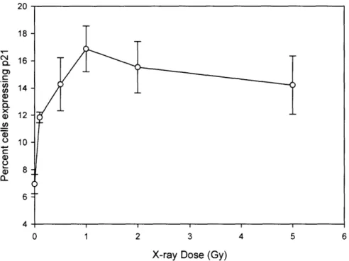
After seeing a bystander p21 wafil induction from keratinocytes co-cultured with
keratinocytes, the bystander effect from directly irradiated human fibroblasts, AGO 1522 cells, co-cultured with bystander keratinocytes via p21 wafl induction was tested, and data
are shown in Figure 3-6. The curve is based only on two experiments, and therefore the error bars represent range and not standard error. A typical plateau is seen by 1 Gy, and a two-fold increase in percentage of cells showing p21 waIfl induction in the bystander
keratinocyte cells is noted.
20 18 16 c .) 14 u) 1 4 ) CL 12 U) -13 4 0 1 2 3 4 5 6
X-ray Dose (Gy)
Figure 3-6: Dose response for induction of p21Wafl in bystander keratinocyte cells
co-cultured with AG01522 cells for 24 h after x-ray irradiation. Data are the averages of
two experiments and error bars represent the range.
3.3 Cell Cycle Delays
Noting the fact that radiation is known to induce a cell cycle arrest, a possible explanation
keratinocytes after Fe ion irradiation compared to that x-rays. Cell cycle analysis was
conducted in cells at 5, 24, 40, and 50 h after irradiation with Fe ion beam and at 5, 24,
and 48 h after x-rays. For x-rays at 5 h, only one experiment was preformed and therefore
no error bars are shown and the 24 h and 48 h results are based only on two experiments.
Figures 3-7,8,9 show cell cycle analysis after x-rays and figures 3-10,11,12,13 show data
from Fe ion irradiation. As seen, a slight G2 arrest is noted in the keratinocytes 5 h after 2
Gy of x-ray irradiation and then is gone by 24 h. No significant differences are
measurable at 0.5 Gy. However, for Fe irradiation, cell cycle delay at G2 is maintained from 5 h until 50 h along with a decrease in G1 and S cells, due to the holding of cells at G2 at 2 Gy. Similar trends are seen at 0.5 Gy, although the magnitude is less.
Ont OSU 70O 60 C) 50 a.) ., 40 0
40-t
() 30 - a-20 -10 -0.0 0.5 1.0 1.5 2.0 2.5X-ray Dose (Gy)
Figure 3-7: Cell cycle distribution in directly irradiated keratinocyte cells 5 h after x-ray irradiation. Data are based on one experiment.
--- G1
---- S phase
- G2
1.0 1.5 X-ray Dose (Gy)
Figure 3-8: Cell cycle distribution in directly irradiated keratinocyte
x-ray irradiation. Data are the averages of two experiments range.
100 80 Li, a-) 0 a) ELU" Q> 60 40 20 0 I 0.0 0.50.5 1.0 1.5
X-ray Dose (Gy)
Figure 3-9: Cell cycle distribution in directly irradiated keratinocyte cells 48 h after x-ray irradiation. Data are the averages of two experiments ± range.
100 80 U) a) 0 60 40
I
-- G1 -- S phase --v--G2.I
20 0 0.0 0.5 2.0 2.5 cells 24 h after 2.5 -*- G1 --O- S phase G2 2.0 I ._ 7 A I--0.5 1.0 1.5 2.0 2.5 Fe Dose (Gy)
Figure 3-10: Cell cycle distribution in Fe ion irradiation. Data are the means
directly irradiated keratinocyte
of at least three experiments ± s.e
0.5 1.0 1.5 2.0
Fe Dose (Gy)
Figure 3-1 1: Cell cycle distribution in Fe ion irradiation. Data are the means
directly irradiated keratinocyte cells 24 h after
of at least three experiments ± s.e
80 70 60 Co 0 0 5) a_ 50 40 30 20 10 0 0.0 cells 5 h after 80 70 60 .n C) 0 a) C) 50 40 30 20 10 0 0.0 2.5
ou -70 60 cn 4)
50-0
- 40-a) C) 30 20 10 - 0--- G1 -0- S phase - G2I
~~~-_
~
0.0 0.5 1.0 1.5 2.0 2.5 Fe Dose (Gy)Figure 3-12: Cell cycle distribution in directly irradiated keratinocyte cells 40 h after Fe ion irradiation. Data are the means of at least three experiments ± s.e
ou 70 60 __ 50 C) c: 40-a)20 D.. 30 -20 -10
0-
-~~~~~~~---- G1 --O-- S phase -- G2 0.0 0.5 1.0 1.5 2.0 2.5 Fe Dose (Gy)Figure 3-13: Cell cycle distribution in directly irradiated keratinocyte cells 50 h after Fe ion irradiation. Data are the means of at least three experiments ± s.e
, _
3.4 Micronuclei Formation
For micronuclei induction, to insure that the micronuclei counted are from the parent cell and not the daughter cell, in the generally used protocol, cytochalasin B is added to halt the cells in a binucleated form (Nilsson et al. 1973). However, it was noticed that when adding cytochalasin B to keratinocytes and scoring for MN, no bystander response was seen after x-rays. Although, when the cells were fixed 24 hours after irradiation and no
cytochalasin B was used, a bystander effect was seen. Figure 3-14 shows directly
irradiated nuclei of cells that received 2 Gy of x-rays and there is noticeable MN
formation, without cytochalasin B in cells fixed 24 hours after irradiation. Figure 3-15
shows two experiments of MN induction with and without cytochalasin B. It is seen that the direct curves are similar, with the addition of cytochalasin B decreasing the number of MN slightly. However, it is clearly seen that no bystander effect is present with cytochalasin B, although without cytochalasin B a typical plateauing curve is observed
with a two-fold increase in this bystander response. Although only one curve is shown for
each experiment, repeats have been done and consistently showed the lack of the
bystander effect with the addition of cytochalasin B and presence of the bystander effect without the addition of cytochalasin B.
Figure 3-14: In situ fluorescence detection of micronuclei in directly irradiated
keratinocyte cells 24 h after 2 Gy x-ray irradiation.
30 25
z
' 20
u) Q .. . O X ) 15 a) 0 c 10 Q) a1) OL 5 0 ' '/~0 - Direct (+cytoB) / ' . . . O .0 Direct (-cytoB) 0/~ O~ ---- Bystander (-cytoB) - Bystander (+cytoB) 0 */ v- / ~ - - ---- _ -v-- - _ _ _ , _ - -0 1 2 3 4 5 6X-ray Dose (Gy)
Figure 3-15: Comparison of dose response curves for induction of MN in keratinocytes after x-rays with and without cytochalasin B. Samples with
cytochalasin B were fixed 72 h after irradiation. Samples without cytochalasin B were fixed at 24 h. Data shown are based on one experiment.
A dose response curve for MN bystander effect from keratinocytes to keratinocytes was
obtained for x-rays and is shown in Figure 3-16. A linear curve is seen in MN response for directly irradiated cells up to 2 Gy, then a decline at 5 Gy. The bystander effect is also
seen with a two-fold increase in MN expression in the keratinocyte bystander cells, 24 h after irradiation. The same assay was done with the Fe ion beam, but with time points of
24, 48 and 72 h after irradiation. Figure 3-17 shows the direct response of MN for the
three time points in the keratinocytes after Fe ions. As seen, the largest MN expression for directly irradiated keratinocytes occurs after 48 hours. Table 3.1 shows the percent of MN expression in the bystander cells for the three time points after Fe irradiation. No conclusive bystander effect is seen in the keratinocytes in the form of MN from Fe beam irradiation. m 3 C. V) cm 25 so co co o 20
z
0) 15 Ce (n a) .10 w en a) 0 5 CD a) a.) n 0 0 1 2 3 4 5 6X-ray Dose (Gy)
Figure 3-16: Dose response for induction of micronuclei from directly irradiated and
bystander keratinocyte cells 24 h after x-ray irradiation. Data are the means of at
.03 mcC. 0B 0 o 0 C
z
Q. Cn SD a) X a) 0 0 z a) 0 50 40 30 20 10 0 0.0 0.5 1.0 1.5 2.0 2.5 3.0 3.5 Fe Dose (Gy)Figure 3-17: Dose response for induction of micronuclei from directly irradiated
keratinocyte cells 24, 48, and 72 h after Fe ion irradiation. Data are the means of at
least three experiments ± s.e.
(a) 24 hours
Dose (Gy) Experiment 1 Experiment 2 Experiment 3
Bystander Bystander Bystander
% MN %MN %MN 0 1.6 1.4 0.05 2.0 8.2 1.5 0.1 2.3 3.0 0.5 1.7 3.6 1.9 2 1.3 5.1 0.77 3 0.99 4.1 1.2
(b) 48 hours
Dose (Gy) Experiment 1 Experiment 2 Experiment 3
Bystander Bystander Bystander
% MN %MN %MN 0 1.8 3.1 0.9 0.05 2.4 3.1 1.3 0.1 2.6 4.5 0.53 0.5 1.7 4.7 0.55 2 3.1 5.3 1.5 3 1.3 4.8 1.1 (c) 72 hours
Dose (Gy) Experiment 1 Experiment 2 Experiment 3
Bystander Bystander Bystander
% MN %MN %MN 0 0.93 3.0 0.56 0.05 0.93 2.6 1.1 0.1 2.9 4.2 0.5 3.1 4.3 1.2 2 1.5 2.8 0.94 3 2.4 4.6 1.6
Table 3.1 Dose response for induction of MN in keratinocyte bystander cells
co-cultured with directly irradiated keratinocyte cells from Fe ion irradiation. (a) 24 h;
(b) 48 h; (c) 72 h after irradiation.
Once the bystander effect was seen via the induction of MN in keratinocytes after x-rays, the MN bystander effect from AGO 1 522 cells and keratinocytes was studied for both radiation types. Figure 3-18 shows the induction of MN in bystander keratinocytes co-cultured with directly irradiated AGO 1522 cells, and Figure 3-19 shows the induction of
MN in the bystander AGO 1522 cells co-cultured with the directly irradiated
keratinocytes for 24 hours after x-rays. The bystander keratinocytes show a two-fold
increase in MIN induction with a plateau reached by the 0.5 Gy x-ray dose to the
AGO 1522 cells. Similarly, the AGO 1522 bystander cells show a two-fold increase in MN
AGO(D)Kera() - Kera(I) Graphed
0 1 2 3 4 5 6
X-ray Dose (Gy)
Figure 3-18: Dose response for induction of MN in bystander keratinocyte cells
co-cultured with directly irradiated AG01522 cells for 24 h after x-rays. Data are the
means of at least three experiments ± s.e.
0 1 2 3 4 5 6
X-ray Dose (Gy)
Figure 3-19: Dose response for induction of MN in bystander AG01522 cells co-cultured with directly irradiated keratinocyte cells for 24 h after x-rays. Data are the means of at least three experiments ± s.e.
5.0 4.5 4.0 3.5 3.0 2.5 2.0 1.5
a
0 0 M, x ..>, V) b O 02 a-'v , x CD C ._..Q CL a Cn -C. 0~ t-0o 0 oz
E 0) C i) a, 0_Q LLI .en a) 0 a, 3.0 2.5 2.0 1.5 1.0 0.5Data obtained for MN bystander induction from the co-cultures of the two cell lines exposed to the Fe beam showed two major differences from the results with x-rays. First, a bystander effect was seen from irradiated AGO 1522 cells to keratinocyte bystander
cells, with a two-fold increase in expression, but no visible bystander effect was seen
from directly irradiated keratinocytes to AGO 1522 cells at any of the four time points
tested, 5, 24, 40, and 50 h. Secondly, the bystander effect in keratinocytes was only seen 50 hours after irradiation of the AGO 1522 cells with the Fe ion beam. Table 3.2
summarizes the above mentioned data.
(a) Keratinocyte 50 h
(Bystander)
Dose (Gy) Experiment 1 Experiment 2
% MN % MN 0 1.7 2.1 0.1 3.6 4.4 2 2.7 (b) AG01522 50 h (Bystander)
Dose (Gy) Experiment 1 Experiment 2
% MN % MN
0 0.92 1.4
0.1 0.97 1.7
2 1.1 1.9
Table 3.2 Co-cultured bystander samples from Fe ion irradiation. (a) Bystander
response in keratinocytes co-cultured with directly irradiated AGO 1522 cells for 50 h
after Fe ion irradiation. (b) Bystander response in AGO 1522 cells for co-cultured with directly irradiated keratinocytes 50 h after Fe ion irradiation.
3.5 Chromatin Bridge Expression
Chromatin bridge expression was scored in irradiated and bystander keratinocytes for
formation 48 h after 3 Gy of Fe ion beam in directly irradiated keratinocyte cells. The
chromatin bridges vary in length and width, and often are accompanied by micronuclei.
Also, as can be seen from the image, the cells appear to have distinct cytoplasms. Figure
3-21 shows the induction of chromatin bridges by x-rays in directly irradiated
keratinocytes, and Figure 3-22 shows the induction of chromatin bridges by Fe ions in
directly irradiated keratinocytes. Neither irradiation type showed a bystander effect via chromatin bridge induction. Also, in the Fe ion data, it is seen that the chromatin bridge expression is highest at 48 h, where the x-ray data are from cells fixed 24 h after
irradiation. The Fe ion data show that this radiation is more effective at inducing chromatin bridges than x-rays.
Figure 3-20: In situ fluorescence detection of chromatin bridges in directly irradiated
0 1 2 3 4 5 6
X-ray Dose (Gy)
Figure 3-21: Dose response for induction of chromatin bridges in
keratinocyte cells 24 h after x-ray irradiation. Data are the means
experiments ±- s.e. directly irradiated of at least three ID CD 'O m C 1-._ E 0o 0) .'S Cn 8U, x wLU () 0 O. 16 14 12 10 8 6 4 2 0 0.0 0.5 10 15 2.0 2.5 3.0 3.5 Fe Dose (Gy)
Figure 3-22: Dose response for induction of chromatin bridges in directly irradiated
keratinocyte cells 24, 48, and 72 h after Fe ion irradiation. Data are the means of at
least three experiments ± s.e.
a) ID 'a V C n E 0 r-S 0) o C .C/)0 C1., a) 0 25 20 15 10 5 0
Chapter 4
Discussion
4.1 Effects on Directly Irradiated Cells
A typical low LET survival curve has a prominent repair shoulder at the low doses before
decreasing in survival in the exponential portion. A high LET curve shows no repair
shoulder and is entirely exponential (Hall 2000). The curves obtained for keratinocytes after 250 kVp x-rays and 1000 MeV/nucleon Fe showed these trends. A repair shoulder is
seen in the x-ray irradiation curve up until 2 Gy. The Fe ion beam is more effective at decreasing survival, where at 10% survival; an RBE is calculated at approximately 2.8.
The protein p21 wafn is known to play a central role in DNA replication and cell cycle progression. It has been shown to be expressed downstream of p53, a tumor
suppressor gene. In general, if p21wal over expression is seen in cells with wild-type p53, then the cell has activated p53. By staining for p21w a , both p21w afl and p53 induction can be concluded (Fei and El-Deiry 2003). Looking at the p21 wafl expression in directly
irradiated keratinocyte cells, a sharp increase is seen by 1 Gy, and the response tends to plateau by 5 Gy at 24 hours after x-rays. From Fe ion irradiation however, p21 wafl over
expression as examined by immunofluorescence does not occur until 40-50 hours post irradiation. Yet, at 40-50 hours, the Fe ion beam is more effective at inducing p21 wafl