HAL Id: hal-00859472
https://hal.inria.fr/hal-00859472
Submitted on 8 Sep 2013
HAL is a multi-disciplinary open access
archive for the deposit and dissemination of
sci-entific research documents, whether they are
pub-lished or not. The documents may come from
teaching and research institutions in France or
abroad, or from public or private research centers.
L’archive ouverte pluridisciplinaire HAL, est
destinée au dépôt et à la diffusion de documents
scientifiques de niveau recherche, publiés ou non,
émanant des établissements d’enseignement et de
recherche français ou étrangers, des laboratoires
publics ou privés.
Extraction and Evolution of Architectural Variability
Models in Plugin-based Systems
Mathieu Acher, Anthony Cleve, Philippe Collet, Philippe Merle, Laurence
Duchien, Philippe Lahire
To cite this version:
Mathieu Acher, Anthony Cleve, Philippe Collet, Philippe Merle, Laurence Duchien, et al.. Extraction
and Evolution of Architectural Variability Models in Plugin-based Systems. Software and Systems
Modeling, Springer Verlag, 2013, 27 p. �10.1007/s10270-013-0364-2�. �hal-00859472�
Extraction and Evolution of
Architectural Variability Models
in Plugin-based Systems
Mathieu Acher1, Anthony Cleve2, Philippe
Collet3, Philippe Merle4, Laurence Duchien4,
Philippe Lahire3
1
Irisa, Inria and University of Rennes 1, France e-mail: [email protected]
2
PReCISE Research Centre, University of Namur, Belgium e-mail: [email protected]
3
Universit´e Nice Sophia Antipolis - I3S (CNRS UMR 7271), France
e-mail: {collet,lahire}@i3s.unice.fr
4
Inria Lille - Nord Europe, University of Lille 1 - CNRS UMR 8022, France
e-mail: {philippe.merle,laurence.duchien}@inria.fr Revised: 30th may 2013
Abstract Variability management is a key issue when
building and evolving software-intensive systems, mak-ing it possible to extend, configure, customize and adapt such systems to customers’ needs and specific deploy-ment contexts. A wide form of variability can be found in extensible software systems, typically built on top of plugin-based architectures that offer a (large) number of configuration options through plugins. In an ideal world, a software architect should be able to generate a sys-tem variant on-demand, corresponding to a particular assembly of plugins. To this end, the variation points and constraints between architectural elements should be properly modeled and maintained over time (i.e., for each version of an architecture). A crucial, yet error-prone and time-consuming, task for a software architect is to build an accurate representation of the variabil-ity of an architecture, in order to prevent unsafe archi-tectural variants and reach the highest possible level of flexibility. In this article, we propose a reverse engineer-ing process for producengineer-ing a variability model (i.e., a fea-ture model) of a plugin-based architecfea-ture. We develop automated techniques to extract and combine different variability descriptions, including a hierarchical software architecture model, a plugin dependency model and the software architect knowledge. By computing and reason-ing about differences between versions of architectural feature models, software architect can control both the variability extraction and evolution processes. The pro-Send offprint requests to:
posed approach has been applied to a representative, large-scale plugin-based system (FraSCAti), considering different versions of its architecture. We report on our experience in this context.
1 Introduction
As a majority of software applications are now large-scale, business-critical, operated 24/7, distributed and ubiquitous, their complexity is increasing at a rate that outpaces all major software engineering advances. In or-der to tame such a complexity, Software Product Line (SPL) engineering is one of the major trends of the last decade. An SPL can be defined as “a set of software-intensive systems that share a common, managed set of features and that are developed from a common set of core assets in a prescribed way” [17]. SPL engineering aims at generating tailor-made variants for the needs of particular customers or environments and promotes the systematic reuse of software artifacts. An SPL de-velopment process usually starts with an analysis of the domain to identify commonalities and variabilities be-tween the members of the SPL. It is common to express SPL variability in terms of features, which are domain abstractions relevant to stakeholders. For this purpose, a Feature Model (FM) is generally used to compactly define all features in an SPL as well as their valid com-binations [61, 21].
Besides large software systems are now commonly organized around a more or less explicit architecture, which defines entities, their properties and relationships. When SPL engineering principles are followed from the start, it is feasible to manage variability through one or more architectural FMs and then associate them to the system architecture [52]. The major architectural vari-ations are then mapped to given features, allowing for automated composition of architectural elements when features are selected to configure a particular software product from the line. A resulting property of crucial importance is to guarantee that the variability is not only preserved but also kept consistent across all arte-facts [20, 12, 40].
In many cases, however, one has to deal with (legacy) software systems not initially designed as SPLs
[66, 29, 73, 3, 55]. When the system becomes more com-plex, with many configuration and extension points, its variability must be handled according to SPL techniques. In this context, the task of building an architectural FM is very arduous for software architects. They typically have to deal with lots of plugins (usual customizations of the Eclipse IDE are made with several hundreds of plu-gins, corresponding to dozens of high-level features [27, 53]), for which safe composition is the topmost require-ment [40].
It is then necessary to recover a consistent FM from the actual architecture. On a large scale both automatic extraction from existing parts and the architect knowl-edge should ideally be combined to achieve this goal. In particular, a software architect should be able to deter-mine whether her (high-level) representation complies with an automatically extracted model, and to what ex-tent they differ from each other (e.g., in the style of reflexion models [49]). Moreover, since the software ar-chitecture and functionalities are naturally evolving over time, it is also necessary to ensure that an architectural FM is maintained consistent with these changes. In the case of modern dynamic software architectures, which are based on plugins, these modifications can be very complex to handle, especially in presence of hidden de-pendencies between (different versions of) plugins. In this context, evolving the architectural FM along the modified architecture is tedious. It is therefore needed to reproduce the extraction process and to reason on the new architectural FM and on its differences.
In this article, we present a comprehensive, tool sup-ported process for reverse engineering and evolving ar-chitectural FMs. We show how techniques for FM slic-ing [5] and differencslic-ing [7] can be adapted and applied in the particular context of architectural FM extraction, analysis and evolution. Specifically, we develop auto-mated techniques to extract and combine different vari-ability descriptions of a software architecture, integrat-ing the hierarchical decomposition of the architecture and inter-plugin dependencies. The basic idea is that variability and technical constraints of the plugin depen-dencies are projected onto an architectural model. After the extraction, alignment and reasoning techniques are applied to integrate the architect knowledge and rein-force the extracted FM. In addition to this extraction process, previously presented in [2], we also show how the process can be reiterated when the architecture evolves. This notably enables the architect to re-integrate his/her knowledge and to reason about the differences between two successive architectural FMs.
Furthermore we evaluate our proposal on different versions of FraSCAti. Overall the results show the soft-ware architect increases the quality of architectural FMs (i.e., better specifying variability and thus avoiding some unsafe configurations) compared to an FM that is manu-ally designed or that does not integrate all variability de-scriptions of the system. Furthermore the architectural FM takes into account both the software architect view-point and the variability actually supported by the sys-tem. Without the FM management support exposed in the article, obtaining similar results would not be possi-ble.
The target audience of this article is threefold. It is first relevant to software systems’ modelers, providing insights on the kind of models that can be built and evolved to capture architectural variability. Software ar-chitects may also be interested in the experience report
on a representative, non-trivial and still evolving plugin-based system. Finally the third target audience regroups researchers and practitioners interested in software vari-ability extraction and management.
The remainder of this article is organized as follows. In Section 2, we give some background on the FraS-CAti case study and foundations of feature modeling. Section 3 identifies two key challenges when managing the architectural variability of a plugin-based system. We also outline our contributions to face those two chal-lenges. In Section 4, we describe in detail the automated extraction process that we have developed. The extrac-tion is tool-supported and processes various documents until generating an architectural FM. Section 5 shows how the process is completed by refinement steps that enable the architect to compare and integrate her knowl-edge, with the aim to obtain a consistent architectural FM. In Section 6, we describe the tools supporting our approach. The overall process is then validated in Sec-tion 7, which presents its applicaSec-tion to the FraSCAti architecture. We also discuss threats to validity. A re-lated work discussion is provided in Section 8 including a comparison of the proposed FM management support with existing techniques. In Section 9 we summarize our contributions, discuss some lessons learned, and antici-pate future work.
2 Background
2.1 The FraSCAti Plugin-based System Case Study We motivate and illustrate our proposal on a case study related to the FraSCAti platform [47], an open source implementation of the OASIS’s Service Component Ar-chitecture (SCA) standard [50]. SCA is a technology-agnostic component-based standard for building distribu-ted composite service-oriendistribu-ted applications mixing vari-ous programming languages and frameworks (e.g., Java, C, C++, WS-BPEL, Spring Framework) for implement-ing business components, various interface definition lan-guages (e.g., WSDL, Java) for describing business ser-vices, and various network communication protocols (e.g., Web Service, Java Messaging Service) for interconnect-ing distributed applications.
Main SCA component-based concepts are quite gene-ric and present in numerous other component models: a composite is a component composed of a set of com-ponents, a component encapsulates a business logic im-plemented with a programming language/framework, a service and a reference are named interfaces respectively provided/required by a component, an interface is a set of methods implemented or used by a component, a bind-ing explains how both service and reference are acces-sible via a network communication protocol, and a wire connects a source reference to a target service.
Started in 2007, the development of FraSCAti be-gun with a framework based on a basic implementation
of the standard, that has then been incrementally en-hanced. After six major releases, it now supports sev-eral SCA specifications (Assembly Model, Java Common Annotations & APIs, Java Component Implementation, Spring Component Implementation, WS-BPEL Client & Implementation, Web Services Binding, JMS Bind-ing, Transaction Policy), and provides a set of exten-sions to the standard, including component implemen-tation types (SCA composite, Java, EJB, WS-BPEL, C, Spring, Fractal, OSGi, Scala, and BeanShell, FScript, Groovy, JavaScript, JRuby, Jython, XQuery, Velocity scripting languages), binding implementation types (SO-AP, JMS, Java RMI, HTTP, REST, JSON-RPC, JNA, UPnP, OSGi, JGroups), interface description types (WS-DL, Java, UPnP, C headers), and runtime APIs for com-ponent introspection and reconfiguration [64, 65].
As its capabilities grew between releases, FraSCAti has itself been refactored and completely architected as an SCA-based application, i.e., an assembly of SCA com-ponents. The FraSCAti architecture is composed of three main SCA composites:
– The SCA parser is responsible to load business SCA composite files into memory. As the SCA compos-ite language is extensible, its grammar is described by several meta-models (MM). Then FraSCAti sup-ports various SCA meta-models (e.g., M M F rascati, M M T uscany).
– The Assembly Factory is responsible to check SCA composites and orchestrate their instantiation. The assembly factory is composed of several plugins for dealing with the various forms of component imple-mentations, interface definition languages, and ser-vice bindings (e.g., rest, http).
– The Component Factory is in charge of instantiating SCA components. This factory generates and com-piles Java code for component containers. This fac-tory has two plugins for supported Java compilers (i.e., J DK6 and J DT ).
Thanks to its new component-based architecture, dif-ferent variants of FraSCAti can be built in order to meet various application requirements and target system con-straints. Each SCA application running on FraSCAti could have different requirements in terms of SOA fea-tures like supporting SOAP, WSDL, WS-BPEL, REST, OSGi, JMS. All these SOA features are implemented as SCA components which are plugged to the FraSCAti ar-chitecture. Then, application developers could select all the FraSCAti plugins required for their applications. Or-thogonally, the target system on which applications are deployed could impose some constraints. For instance, FraSCAti applications could be deployed on standalone Java Runtime Environments (JRE), Web application servers, or OSGi gateways. Each of these target environments is supported by a specific pluggable FraSCAti compo-nent. FraSCAti could require to compile Java code on the fly, then FraSCAti requires an embedded Java
com-piler. FraSCAti supports two distinct Java compilers: The standard JDK6 compiler and the Eclipse JDT com-piler. FraSCAti plugins could have dependencies, e.g., the REST binding plugin requires the FraSCAti meta-model while the HTTP binding plugin requires the Tus-cany meta-model. These FraSCAti plugin dependencies
are captured via Apache Maven1 XML-based
descrip-tors.
FraSCAti version 1.5 contains around 60 plugins for a total of around 250.000 lines of code. So, FraSCAti is representative of a large plugin-based system, i.e., a sys-tem composed of plugins, each of which is implemented as a set of SCA components that adds specific abilities to FraSCAti.
With all these capabilities, the FraSCAti platform has become highly (re-)configurable in many parts of its own architecture. It exposes a larger number of ex-tensions that can be activated throughout the platform, creating numerous variants of a FraSCAti deployment. It then became obvious to FraSCAti technical leaders that the variability2of the platform should be more sys-tematically managed as an SPL in order to better drive and control its evolution.
2.2 Foundations of Feature Modeling
Variability modeling is a central activity in SPL engi-neering. We choose to rely on a particular kind of vari-ability model, Feature Models (FMs), based on their wide adoption, the existence of formal semantics, rea-soning techniques and tool support [61, 14]. FMs com-pactly represent product commonalities and variabilities in terms of features [20, 39, 12]. The FMs that we con-sider all along this article usually express architectural variability, meaning that FMs are devoted to the mod-eling of the variation points (and their relationships) in a given architecture.
An FM hierarchically structures features into multi-ple levels of detail. The hierarchy of an FM is represented by a rooted tree composed of a finite set of features and a finite set of edges (edges represent top-down hierarchical decomposition of features, i.e., parent-child relations be-tween them). As an example, Fig. 1(a) shows a excerpt of the architectural FM of FraSCAti as described in the previous section.
As in typical SPLs, not all combinations of features (or configurations, see Definition 1) are valid. Variabil-ity defines what the allowed configurations are. When decomposing a feature into subfeatures, the subfeatures may be optional, mandatory, exclusive (e.g., J DK6 and
1 Maven (http://maven.apache.org/) is a software tool
for managing a project’s build, reporting and documentation
2 We use here the term variability as in the definition from
[67]: “software variability is the ability of a software system or artefact to be efficiently extended, changed, customized or configured for use in a particular context.”
FraSCAti SCAParser Java Compiler JDK6 JDT Assembly Factory rest http Binding MMFrascati Component Factory Metamodel MMTuscany constraints
rest implies MMFrascati http implies MMTuscany
fm
1 Optional Mandatory Xor-Group Or-Group(a) an architectural FM (simplified from our case study) Jf m1K = {
C ∪ {J DT, http, M M T uscany},
C ∪ {M M F raSCAti, J DK6, http, M M T uscany}, C ∪ {M M F raSCAti, J DK6, rest},
C ∪ {M M F raSCAti, J DK6, rest, M M T uscany}, C ∪ {M M F raSCAti, J DT, rest},
C ∪ {M M F raSCAti, J DK6, http, rest, M M T uscany}, C ∪ {M M F raSCAti, J DT, http, M M T uscany}, C ∪ {M M F raSCAti, J DT, rest, M M T uscany}, C ∪ {M M F raSCAti, J DT, http, rest, M M T uscany}, C ∪ {J DK6, http, M M T uscany}
} with
C = {F raSCAti, SCAP arser, AssemblyF actory, ComponentF actory, M etamodel, Binding, J avaCompiler}
(b) corresponding set of configurations
φ1 = F raSCAti
∧ F raSCAti ⇔ AssemblyF actory ∧ F raSCAti ⇔ ComponentF actory ∧ F raSCAti ⇔ SCAP arser ∧ SCAP arser ⇔ M etamodel ∧ AssemblyF actory ⇔ Binding
∧ ComponentF actory ⇔ J avaCompiler ∧ J avaCompiler ⇒ J DK6 ∨ J DT ∧ ¬ J DK6 ∨ ¬J DT ∧ M M F rascati ⇒ M etamodel ∧ M M T uscany ⇒ M etamodel ∧ http ⇒ Binding ∧ rest ⇒ Binding ∧ Binding ⇒ rest ∨ http ∧ rest ⇒ M M F rascati ∧ http ⇒ M M T uscany
(c) corresponding propositional formula Fig. 1 Feature model, set of configurations and propositional logic encoding
J DT form an Alternative-group), or inclusive (e.g., http and rest form an Or -group). An additional mechanism to specify variability is to add constraints (expressed in propositional logic), which may cut across the feature hierarchy (e.g., rest requires M M F rascati). The valid-ity of a configuration is determined by the semantics of FMs, e.g. J DK6 and J DT are mutually exclusive and cannot be selected at the same time.
The terms FM and feature diagram are employed in the literature, usually to denote the same concept. In this article, we consider that a feature diagram (see Def-inition 1) includes a feature hierarchy (tree), a set of feature groups, as well as human readable constraints (implies, excludes).
Definition 1 (Feature Diagram) A feature diagram F D = hG, r, EM AN D, GXOR, GOR, I, EXi is defined as follows:
– G = (F , E, r) is a rooted tree where F is a finite set of features, E ⊆ F × F is a finite set of edges and r ∈ F is the root feature;
– EM AN D⊆ E is a set of edges that defines mandatory features with their parents;
– GXOR ⊆ P(F ) × F and GOR ⊆ P(F ) × F define
feature groups and are sets of pairs of child features together with their common parent feature;
– a set of implies constraints I whose form is A ⇒ B and a set of excludes constraints EX whose form is A ⇒ ¬B (A ∈ F and B ∈ F ).
Features that are neither mandatory features nor in-volved in a feature group are optional features. A parent feature can have several feature groups but a feature must belong to only one feature group.
Similarly to [66], we consider that an FM is composed of a feature diagram plus a propositional formula (see Definition 2).
Definition 2 (Feature Model) A feature model F M is a tuple hF D, ψcsti, where F D is a feature diagram and ψcst is a propositional formula over the set of features F . Definition 3 (Configuration semantics) A configu-ration of a feature model f mi is defined as a set of se-lected features c = {f1, f2, . . . , fm} ⊆ Fi.Jf miK denotes the set of valid configurations of the feature model f mi
and is thus a set of sets of features. We note φi the
fmSA fmArch1 Automated Extraction fmArch2 Automated Extraction fmArchN Automated Extraction v1.3 v1.4 v2.0 Modeling
Reverse Engineering
Forward Engineering
(out of the scope of the paper)
configurators
variant generation
Fig. 2 Extraction and evolution of architectural variability
The set of configurations represented by an FM can be described by a propositional formula defined over a set of Boolean variables, where each variable corresponds to a feature [21]. Fig. 1(c) shows the mapping of the FM to a propositional formula. The propositional formula can be used to automatically reason about properties of an FM (e.g., see [14]). In particular, if an assignment to its Boolean variables is satisfiable, then the selec-tion/deselection of the corresponding features respects the rules evoked above.
We chose the formalism of FMs in its Boolean (and most popular [14]) form since the expressiveness fits our needs: variability sources encountered in FraSCAti can be logically translated into such FMs.
3 On Architectural Variability Management Several software artefacts (SCA composite files, Maven descriptors, informal documents) describe the architec-ture of FraSCAti, but the supported variability is not made explicit. Moreover, the raise of complexity in its maintenance and evolution led its software architect to control in a more systematic way the variability, based on product line principles.
To this aim, we needed to extract the supported vari-ability from its actual architecture, and to reason about
this variability when evolving the architecture, both for refactoring the system as an SPL or for developing new functionalities. We thus faced two challenges: a first one related to the extraction of architectural variability mod-els; a second one about the management of the evolution of the FraSCAti architecture and of the corresponding models.
Challenge 1: Extraction of Architectural FMs A first and essential step is therefore to identify and represent the variability of a system, including complex constraints between architectural elements. As exposed in Fig. 2, a variability model (i.e., an FM) can be ex-ploited afterwards to pilot a configuration or derive spe-cific variants3.
Unfortunately, the task of manually creating the ar-chitectural FM is daunting, time-consuming and error-prone, requiring substantial effort from the software ar-chitect (SA). In this case, as in all large-scale architec-tures, it is very difficult for an architect to guarantee that the resulting FM is consistent with the architec-ture. The scope defined by the FM should not be too
3
The exploitation of the FM in a forward engineering pro-cess is out of the scope of this paper. Numerous generative techniques have been developed (see, e.g., [18, 52, 30]) and we plan to reuse them in our ongoing effort for re-engineering FraSCAti.
large (otherwise some unsafe compositions of the archi-tectural elements are allowed) or too narrow (otherwise it translates as a lack of architectural flexibility). A loose FM simply hampers the systematic and consistent ap-plication of the SPL process, since the property of safe composition does not hold, allowing feature configura-tions that are not realizable by the architecture [48, 68, 20, 33, 40]. In FraSCAti, an example of such a loose FM might be an FM similar to f m1in Fig. 1(a) but without the constraints related REST and HT T P technologies to specific metamodels. In this case, this would allow unsafe configurations involving some rest binding with the M M T uscany metamodel, which are not realizable by the FraSCAti architecture.
Automatic extraction clearly saves time and reduces accidental complexity, but the accuracy of the results directly depends on the quality of the available docu-ments and of the extraction procedure. In the general case, both automatic extraction from existing parts and the architect domain-specific knowledge should be ide-ally combined to achieve this goal.
Challenge 2: Evolution of Architectural FMs As the software architectures, its elements, dynamic plugins and their relations, naturally evolve, the second challenge consists in mastering the evolution of the ar-chitectures and their variability. Software architects have to supervise and control that the evolution of the ar-chitectural FM is correct. In particular, the variability information and constraints should still be conformant with the SA knowledge or with previous versions of an architectural FM.
Several factors make this task tedious and very com-plex. The dynamicity of the software architectures, like in the FraSCAti case, leads to many hidden dependen-cies between plugins, especially when one handles evolv-ing versions of plugins. Consequently, it is not possible to evolve the architectural FM directly and then check its consistency with the modified architecture and plugins, as this process would be very cumbersome, multiplying the changes on the FM without any real guidance.
We see this challenge as related to the first one, as the most appropriate way to tackle it is to reproduce the extraction process and to reason on the old and new architectural FMs. For our case study, the extrac-tion/reconciliation process has to be reiterated on ferent versions of FraSCAti, and then, fine-grained dif-ferences between two successive architecture FM should ideally be presented to the software architect.
Overview of Our Proposal. Several sources of in-formation can be considered when building an architec-tural variability model of a plugin-based system. In the case of FraSCAti, there are three possible sources. They either provide the adequate level of abstraction to man-age the architecture or only focus on variability aspects. But none of them supports both and therefore are not sufficient alone to comprehensively address the Chal-lenge 1:
– the architectural model restitutes the set of elements needed to reason about the software system and the (hierarchical) relations among them. But it usually does not contain any variability information and log-ical constraints between the elements.
– the plugin dependencies specify variation points and their logical dependencies actually supported by the architecture. But they do not reflect the architecture of the system and do not offer an adequate level of abstraction.
– the software architect knowledge can introduce acci-dental complexity (especially regarding variability) and does not necessarily reflect the software archi-tecture as actually implemented. Yet the software ar-chitect has usually a good understanding of his/her architecture and can design the model he/she wants to reason about the software system.
To overcome this limitation, we propose to combine the different sources together. Intuitively, the variability and technical constraints of the plugin dependencies are projected onto the architectural model. As a result, we obtain an architectural model that is both representa-tive of the software architecture and the variability ac-tually supported by the system (by construction). The technical and formal details of the extraction process are described in Section 4.
The problem of integrating the software architect knowledge is addressed in Section 5. We developed tech-niques that allow the software architect to validate and edit (if needs be) the architectural FM extracted by the automated procedure. The key idea is to compute and present to the software architect the differences between two architectural FMs (e.g., the one designed by the soft-ware architect and the one extracted). The differencing techniques can also be used to address Challenge 2 and the evolution of an architecture.
In Section 6, we describe the tooling support we de-veloped for assisting the software architect. In Section 7, the proposed extraction and evolution techniques are ap-plied and evaluated on different versions of FraSCAti.
4 Automatic Extraction of the Architectural Feature Model
This section addresses Challenge 1 (Extraction of Archi-tectural FMs) discussed in Section 3. The general prin-ciple of the extraction is to combine two sources (an architectural model and a set of plugin dependencies) in order to synthesize a new integrated FM representing the features of the architecture as well as their variabil-ity and their technical constraints. Fig. 3 summarizes the steps needed to realize the extraction process.
As a first step, a raw architectural feature model, noted f mArch150, is extracted from a 150% architecture
of the system (see À). The latter consists of the
1 2 Software Artefacts 3 implies fmPlug fmArch150 implies Enforced Architectural FM fmFull fmArch Aggregation Slicing (Π) Mapping propositional constraints Extraction of 150%
Architectural FM Extraction of Plugin Dependencies
Fig. 3 Process for Extracting f mArch
plugins. We call it a 150% architecture because it is not likely that a FraSCAti configuration may contain them all. Consequently, f mArch150 does include all the
fea-tures provided by the FraSCAti SPL, but it still consti-tutes an over approximation of the set of valid combina-tions of features of the FraSCAti family. Indeed, some features may actually require or exclude other features, which is not always detectable in the architecture. Hence the need for considering an additional source of informa-tion. We therefore also analyze the specification of the system plugins and the dependencies declared between them, with the ultimate goal of deriving inter-feature constraints from inter-plugin constraints. To this end, we extract a plugin feature model f mP lug, that repre-sents the system plugins and their dependencies (see Á). Then, we automatically reconstruct the bidirectional mapping that holds between the features of f mP lug and those of f mArch150 (seeÂ). Finally, we exploit this
map-ping as a basis to derive a richer architectural FM, noted f mArch, where additional feature constraints have been added. As compared to f mArch150, f mArch more
accu-rately represents the architectural variability provided by the system.
4.1 Extracting f mArch150
The architectural FM extraction process starts from a set of n system plugins (or modules), each defining an ar-chitecture fragment. In order to extract an architectural
FM representing the entire product family, we need to consider all the system plugins at the same time. We therefore produce a 150% architecture of the system, noted Arch150. It consists of a hierarchy of components. In the SCA vocabulary, each component may be a com-posite, itself further decomposed into other components. Each component may provide a set of services, and may specify a set of references to other services. Services and references having compatible interfaces may be bound together via wires. Each wire has a reference as source and a service as target. Each reference r has a multi-plicity, specifying the minimal and maximal number of services that can be bound to r. A reference having a 0..1 or 0..N multiplicity is optional.
Note that Arch150 may not correspond to the
ar-chitecture of a legal product in the system family. For instance, several components may exclude each other be-cause they all define a service matching the same 0..1 ref-erence r. In this case, the composition algorithm binds only one service to r, while the other ones are left un-bound in the architecture.
Since the extracted architectural FM should repre-sent the variability of the system of interest, we focus on its extension points, typically materialized by optional references (e.g., metamodels of composite ScaParser; implementations, interfaces, bindings and property -types of composite AssemblyFactory; fractal-bootst rap-class-providers, delegate-membrane-generatio n, generators and compiler-provider of composite
ComponentFactory). Algorithm 1 summarizes the be-havior of the FM extractor.
Algorithm 1 ExtractArchitecturalF M150(Arch150)
Require: A 150% architecture of the plugin-based system (Arch150).
Ensure: A feature model approximating the system family (f mArch150).
1:root ← M ainComposite(Arch150) 2:froot← CreateF eature(root)
3:f mArch150← SetRootF eature(f mArch150, froot) 4:for all c ∈ F irstLevelComponents(root) do
5: fc← CreateF eature(c)
6: f mArch150← AddM andatoryChildF eature(f mArch150, froot,
fc)
7: f mArch150← AddChildF eatures(f mArch150, c, fc, Arch150) 8:end for
The root feature of the extracted FM (froot)
corre-sponds to the main composite (root) of Arch150. The
child features of froot are the first-level components of root, the latter being considered as the main system fea-tures. The lower-level child features are produced by the AddChildF eatures function (Algorithm 2).
Algorithm 2 AddChildF eatures(F M, c, fp, Arch150) Require: A feature model (F M ), a component (c), a parent feature
(fp), a 150% architecture (Arch150).
Ensure: F M enriched with the child features of fp, if any. 1:for all r ∈ OptionalRef erences(c) do
2: M C ← F indM atchingComponents(Arch150, r) 3: if M C 6= ∅ then 4: fr← CreateF eature(r) 5: F M ← AddOptionalChildF eature(F M, fp, fr) 6: if M ultiplicy(r) = 0..1 then 7: g ← CreateXORGroup()
8: else if M ultiplicy(r) = 0..N then
9: g ← CreateORGroup()
10: end if
11: F M ← AddGroup(F M, fr, g) 12: for all cs∈ M C do 13: fcs← CreateF eature(cs)
14: F M ← AddChildF eatureOf Group(F M, g, fcs)
15: F M ← AddChildF eatures(F M, cs, fcs, Arch150)
16: end for
17: end if
18: end for
This recursive function looks for all the optional ref-erences r of component c and, for each of them, creates an optional child feature fr, itself further decomposed through a XOR or an OR group (depending on the mul-tiplicity of r). The child features fcs of the group
corre-spond to the set of all components csproviding a service compatible with r.
Algorithm 3 specifies how to retrieve this set of match-ing components from the 150% architecture. The set of components matching a given 0..N reference r are ob-viously those providing a service bound to r via a wire. In the case of a 0..1 reference, in contrast, all compat-ible services are not necessarily bound to it. Thus, the matching components are all those that provide a service having an interface compatible with reference r. Illustration Fig. 4 illustrates the extraction process wh-en applied to FraSCAti. The left-hand side of the figure
Algorithm 3 F indM atchingComponents(Arch150, r)
Require: A 150% architecture Arch150, an optional reference r.
Ensure: The set M C of components defined in Arch150that provide
a service compatible with r.
1: M C ← ∅
2: t ← T arget(r)
3: if M ultiplicy(r) = 0..1 then
4: i ← Interf ace(r)
5: M C ← ComponentsW ithCompatibleServiceInterf ace(Arch
150, i)
6: else if M ultiplicy(r) = 0..N then
7: for all w ∈ W iresHavingAsSource(Arch150, r) do 8: s ← T argetService(w)
9: cs← Component(s) 10: M C ← M C ∪ {cs} 11: end for
12:end if
shows excerpts of the FraSCAti architecture expressed in SCA. The right-hand side of the figure depicts the in-cremental extraction of the architectural feature model f mArch150. FraSCAti, as main composite of the system,
becomes the root feature. The mandatory features at the first level of decomposition correspond to the first-level
composites of FraSCAti, among which sca-parser4. The
latter specifies a 0..N reference metamodels, which is translated into an optional child feature of sca-parser, that in turn serves as parent feature of an OR group. The child features of this group correspond to all the com-ponents that provide a service compatible with the ref-erence metamodels. For instance, this is the case of the component sca-metamodel, providing a service metamo-del-provider wired to the reference metamodels (then lines 7-12 of Algorithm 3 applied).
4.2 Extracting f mP lug
The extraction of the plugin feature model f mP lugstarts from the set of plugins P = {p1, p2, . . . , pn} composing the system. This extraction is straightforward: each plu-gin pi becomes a feature fpi of f mP lug. If a plugin pi is
part of the system core, fpi is a mandatory feature,
oth-erwise it is an optional feature. Each dependency of the form pi depends on pj is translated as an inter-feature dependency fpirequiresfpj. Similarly, each pi excludes
pj constraint is rewritten as an excludes dependency be-tween fpi and fpj.
4.3 Mapping f mArch150 and f mP lug
When producing Arch150, we keep track of the relation-ship between the input plugins and the architectural el-ements they define, and vice versa. On this basis, we specify a bidirectional mapping between the features of f mArch150 and those of f mP lug by means of requires
constraints. This mapping allows us to determine (1)
4
It should be noted that the extraction only focuses on the first-level composites that include some variability. It ignores all the composites that do not contain any optional references
<composite … name="org.ow2.frascati.FraSCAti"> …
<component name="sca-parser">
<implementation.composite name="parser:Parser.composite"/> …
<component name="sca-parser"> …
<reference multiplicity="0..n" name="metamodels" autowire="true"> <interface.java
interface="org.ow2.frascati.parser.api.MetamodelProvider"/> </reference>
…
</component>
<component name="sca-metamodel"> <implementation.java
class="org.ow2.frascati.parser.metamodel.ScaMetamodelProvider"/> <service name="metamodel-provider">
<interface.java
interface="org.ow2.frascati.parser.api.MetamodelProvider"/> </service>
…
<wire source="sca-parser/metamodels"
target="sca-metamodel/metamodel-provider"/> FraSCAti sca-parser metamodels sca-metamodel ... ... FraSCAti sca-parser metamodels ... FraSCAti sca-parser ...
Fig. 4 Extraction of f mArch150 applied to FraSCAti (excerpt).
which plugin provides a given architectural feature, and (2) which architectural features are provided by a given plugin.
4.4 Deriving f mArch
We now explain how we derive f mArchusing f mArch150,
f mP lug, the mapping between f mP lug and f mArch150,
and an operation called slicing. We then illustrate the procedure using the example of Fig. 5. Intuitively, the variability and technical constraints induced by the plu-gin dependencies are projected onto the architectural model. In our case the use of plugin dependencies re-stricts the scope of the architectural FM by precluding some unauthorized configurations in f mArch150.
4.4.1 Projecting Variability onto the Architectural Model First the two FMs f mP lug and f mArch150 are
aggre-gated under a synthetic root F tAggregation so that the root features of the input FMs are mandatory child fea-tures of F tAggregation. The aggregation operation pro-duces a new FM, called F MF ull(see Fig. 5). The propo-sitional constraints relating features of f mP lug to fea-tures of f mArch150 are also added to F MF ull.
Second, we compute the projected set of configura-tions (see Definition 5) of F MF ullonto the set of features of f mArch150(i.e., Ff mArch150 = {Arch, Ar1, . . . , Ar6}).
To realize the projection, we use an operation called slicing (see Definition 4). Given a subset of features, the
slicing operator produces a new FM characterizing the projected set of configurations (see Definition 5). Definition 4 (Slicing) We define slicing as an
oper-ation on FM, denoted ΠFslice (f m) = f mslice where
Fslice= {f t1, f t2, ..., f tn} ⊆ F is a set of features (called the slicing criterion) and f msliceis a new FM (called the slice).
Definition 5 (Slice and projected set of configu-rations) The result of the slicing operation is a new FM, f mslice, such that:Jf msliceK = { x ∩ Fslice| x ∈Jf mK } (called the projected set of configurations).
As several yet different FMs can represent a given set of configurations [66], we also take the feature hier-archy into account. In particular, we want to avoid slice FMs that are not readable and maintainable (e.g., for a software architect or for users configuring the architec-ture) due to an inappropriate hierarchy. Therefore we consider that the new FM produced by the slicing oper-ation should have a hierarchy as close as possible to the hierarchy of the original FM (see Definition 6).
Definition 6 (Slice and feature hierarchy) The fea-ture hierarchy of the slice FM, denoted Gslice= (FF Mslice,
Eslice⊆ E), is defined as follows:
– features include the slicing criterion except dead fea-tures (see Definition 7) of the original FM. Formally: FF Mslice = Fslice\ deads(F M ),
Ar3 => Pl1 Pl2 => Ar5 R Ar2 Ar5 Ar6 Ar1 Ar3 Ar4 Arch fmArch fmFull Ar2 Ar5 Ar6 Ar1 Ar3 Ar4 Arch fmArch Ar3 => Ar5 Pl3 Pl2 Pl1 Plugin Pl1 => Pl2 fmPlug 150 〖 fmFull 〗 = {{Ar1,Ar2,Ar4,Ar6,Arch,R,Pl3,Plugin}, {Ar1, Ar2, Ar3, Ar5, Arch, R, Pl1, Pl2, Pl3, Plugin}, {Ar1, Ar2, Ar4, Ar5, Arch, R, Pl2, Pl3, Plugin}, {Ar1, Ar2, Ar4, Ar5, Arch, R, Pl1, Pl2, Pl3, Plugin}, {Ar1, Ar2, Ar4, Ar5, Arch, R, Pl2, Plugin}, {Ar1, Ar2, Ar4, Ar5, Arch, R, Pl3, Plugin}, {Ar1, Ar2, Ar3, Ar5, Arch, R, Pl1, Pl2, Plugin}, {Ar1, Ar2, Ar4, Ar5, Arch, R, Pl1, Pl2, Plugin}} 〖 fmArch150 〗 = {{Ar1,Ar2,Ar4,Ar6,Arch}, {Ar1, Ar2, Ar3, Ar5, Arch},
{Ar1, Ar2, Ar3, Ar6, Arch}, {Ar1, Ar2, Ar4, Ar5, Arch}}
〖 fmArch 〗 = {{Ar1,Ar2,Ar3,Ar5,Arch}, {Ar1, Ar2, Ar4, Ar6, Arch}, {Ar1, Ar2, Ar4, Ar5, Arch}} Slicing (Π) onto
{ Arch, Ar1, …, Ar6 }
Fig. 5 Enforcing architectural FM using aggregation and slicing: an example
– features are connected to their closest ancestor if their parent feature is not part of the slice FM. Formally: Eslice= {e = (v, v0) | e ∈ E0∧ @ v00∈ F : ((v, v00) ∈ E0∧(v00, v0) ∈ E0)} where G0= (F0, E0) is the transi-tive closure of the feature hierarchy G of the original FM.
Definition 7 (Dead features) A feature f of F M is dead if it cannot be part of any of the valid configura-tions of F M . The set of dead features of F M is noted deads(F M ) = {f ∈ F | ∀c ∈JF M K, f /∈ c}.
4.4.2 Automation Our previous experience in the
com-position of FMs [4] has shown that syntactical strategies have severe limitations to accurately represent the set of configurations expected, especially in the presence of cross-tree constraints. The same observation applies for the slicing operation so that reasoning directly at the se-mantic level is required. The key ideas of our approach are to i) compute the propositional formula representing the projected set of configurations and then ii) reuse the reasoning techniques proposed in [21, 11, 8] to construct an FM from the propositional formula. We rely on the al-gorithm developed in [5] that combines this information with the known hierarchy of the slice (see Definition 6) in order to build a complete and valid FM.
4.4.3 Example In the example of Fig. 5, the resulting
slice is called f mArch. As we want to focus on the varia-tion points of the architecture, it only contains the fea-tures’ name of f mArch150. Formally:
ΠFf mArch
150
(f mF ull) = f mArch
We can verify that the relationship (see Definition 5)
between the input FM, Jf mF ullK, and the slice FM,
Jf mArchK, truly holds:
Jf mArchK = { x ∩ {Ar1, Ar2, Ar3, Ar5, Arch}
| x ∈Jf mF ullK }
Importantly, we can notice that one configuration of the original f mArch150 is no longer present in f mArch:
Jf mArch150K \ Jf mArchK = {Ar1, Ar2, Ar3, Ar6, Arch}
Indeed the slice FM f mArch contains an additional
constraint Ar3 ⇒ Ar5, that was not originally restituted as such in f mArch150
5. It should also be noted that the hierarchy of the slice correctly restitutes the hierarchical decomposition of the architecture.
This very simple example already shows two key ben-efits of combining different variability sources and us-ing the slicus-ing operator. First, constraints, not originally present in the 150% architectural FM, are automatically restitued in a new architectural variability model and can be reported back to the software architect. Second, restrictions are applied on the over approximated con-figurations set characterized by the 150% architectural FM. Therefore some configurations, actually not sup-ported by the architecture, are now precluded.
5 Support for the Evolution of Architectural Feature Models
This section addresses Challenge 2 (Evolution of Archi-tectural FMs) discussed in Section 3.
5 Similarly, the constraint Ar4 ⇒ Ar6 could be restituted
in the model (using the information of the implication graph, see above). The slicing operator does not add this constraint because of the redundancy with Ar3 ⇒ Ar5.
fmSA
fmArch1 Reconciliation, Comparison, Refinement Automated Extraction T0 T1 T2 Tn fmArch'1 fmArch2 Reconciliation, Comparison, Refinement Automated Extraction fmArch'2 fmArchN Reconciliation, Comparison, Refinement Automated Extraction fmArch'N fmArch'N-1 v1.3 v1.4 v2.0 Modeling Software Architect (SA)
Fig. 6 Extraction process and evolution of architectural FMs
For each version of a plugin-based system like FraS-CAti, the architectural FM synthesized by the extrac-tion procedure should be validated by the software ar-chitect (SA). In particular, the SA should control that the variability information and the characterized set of configurations do not contradict his/her intention and knowledge of the architecture. For example, the SA may consider that the mandatory status of some features in the extracted FM is not appropriate.
The idea we defend in this article is that, for assisting the SA, the extracted FM can be compared with his/her mental representation and with older versions of archi-tectural FMs. As a result, an appropriate support for comparing two FMs and reasoning about an evolution of an FM is highly needed.
First evolution. At the starting point of the re-engine-ering of FraSCAti as an SPL, an intentional model of the variability was elaborated by the SA. The resulting FM, denoted f mSA, was the first available representation of the FraSCAti architecture (version 1.3, see Fig. 6). The extraction process previously described was then applied to produce another representation (f mArch1) for the same
version of the architecture. Therefore, f mArch1 can be
seen as an evolution of f mSA given that the FM origi-nally elaborated by the SA has now evolved to an FM automatically extracted.
The absence of a ground truth FM – an FM for which we are certain that each combination of features is supported by the SPL architecture – makes uncertain the accuracy of the variability specification expressed in f mArch1 as well as in f mSA. As both the software
ar-chitect FM and f mArch1 may represent differently the
variability of the architecture, there is need to reconcile and refine the two FMs. The result of this process is a new FM, f mArch0
1, that integrates the intentional
vari-ability and the SA knowledge of f mSAand the explicit variability expressed by f mArch1.
Versions and evolutions. As any software project, the FraSCAti architecture evolves. Many features and de-pendencies are added and removed. Naturally, the ex-traction procedure is reiterated on different versions (e.g., version 1.4) of a FraSCAti architecture, producing as dif-ferent FMs. Nevertheless the confidence of the resulting FMs remains unclear:
– the extraction procedure may be faulty (e.g., inade-quate for a specific version of FraSCAti);
– the variability and the constraints may not be cor-rectly documented in the architecture artefacts; – the SA knowledge may not be taken into account.
Managing the evolutions. For controlling and hope-fully validating the evolution of an FM, the SA should be able to understand and exploit the differences between two FMs. A possible solution is to elaborate, for each ver-sion of a FraSCAti architecture, a new FM representing the current variability and then compare it with the ex-tracted FM. Nevertheless, the elaboration from scratch of a new FM (like the SA did for version 1.3) is time-consuming and error-prone. There is an opportunity to reuse FMs resulting from a refinement. Then, similarly
to what has been done when reasoning about f mSAand
f mArch, reconciliation and comparison techniques are applied. For example, as shown in Fig. 6, f mArch0
1
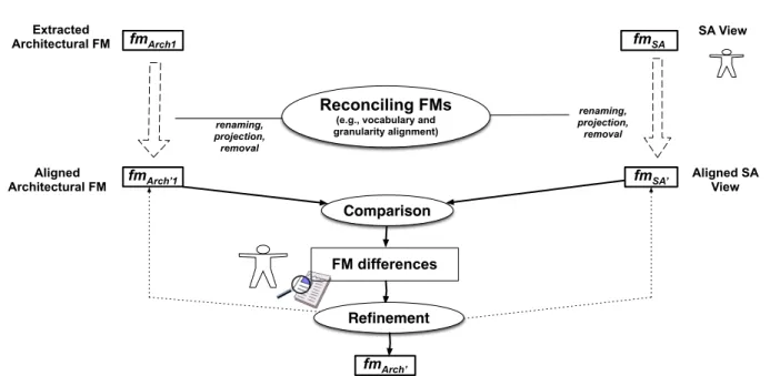
SA View renaming, projection, removal Aligned SA View Extracted Architectural FM Aligned Architectural FM renaming, projection, removal fmSA fmSA’ fmArch’1 fmArch1 Reconciling FMs
(e.g., vocabulary and granularity alignment)
Comparison FM differences
Refinement fmArch’
Fig. 7 Process for integrating the SA knowledge: reconciliation, comparison and refinement
compared with f mArch0
2 (extracted FM for version 1.4
of FraSCAti).
Support for managing evolutions. Fig. 7 presents the overall process for comparing two FMs (e.g., for compar-ing an extracted FM with an FM designed by the SA). In the following, we describe dedicated techniques related to the evolution of FMs for supporting the SA activities, namely reconciliation (see Section 5.1), comparison and refinement (see Section 5.2).
5.1 Reconciliation of Feature Models
Let us consider f mSA and f mArch of Fig. 7. The SA
should be able to determine if the variability choices in f mSA comply with what is expected by himself (i.e., as specified in f mArch), and vice-versa. In case variability choices are conflicting, the SA can refine the architec-tural FM. Similar observations can be made when rea-soning about two different versions of a FraSCAti archi-tecture.
A first obstacle concerns the need to reconcile the two
FMs (e.g., f mArch and f mSA). Both FMs come from
difference sources or versions. A preprocessing step is needed before reasoning about their relationship. Firstly, the vocabulary (i.e., names of features) used in both FMs may differ from each other, and should be aligned consequently. Many operations (see below) indeed
as-sume6 that features are identified by an unique label
(i.e., name) in an FM and that two features of two FMs match if and only if they have the same name.
To avoid unexploitable differencing results, some pre-directives are needed and consist in renaming features. We rely on string matching techniques (e.g., Levenshtein
6
This assumption is also shared by [70, 63, 26].
distance) to automatically identify corresponding fea-tures. More sophisticated matching techniques already integrated in model-based tools (e.g., see [25, 37]) can also be considered but have not been used in the con-text of FraSCAti (see next section).
Secondly, granularity details differ. For example some features in one FM are not present in the other FM. The removal of features is thus needed. This questions the se-mantics of the removal operation. What about cross-tree constraints involving a feature that has been removed? What about variability information of the parent and children features when a feature is removed in the mid-dle of a hierarchy?
We consider that, when a feature is removed, two values (true or false) can be assigned and should be con-sidered accordingly. This operation cannot be done syn-tactically in the general case. We rely on the slicing op-eration previously defined that can removed a set of fea-tures while guaranteeing configuration semantics prop-erties. For example, the removal of two features F elix
and Equinox of f mSA, leading to a new FM f m0SA,
corresponds to the following slicing operation: f m0SA= ΠFf mSA \ {F elix,Equinox} (f mSA)
5.2 Comparison and Refinement of FMs: A Toolbox
At this step, we can compare the two FMs (e.g., reason about the relationship between f mArch and f mSA). It means we need to compute and present differences of the two FMs in a comprehensible manner to the SA. The problem of FM differences is a general problem that may occur in other contexts (e.g., management of a product line offering) [7]. We present here only the techniques relevant to our specific context.
5.2.1 Principles of FM Differences Several techniques for the differencing (for short, diff ) of FMs can be
con-sidered. Let f m1 and f m2 be two FMs. Roughly, the
diff between f m1 and f m2 is the set of elements in
f m1 but not in f m2. From a syntactical perspective, the elements to be considered in the diff may be fea-tures, feature hierarchies, feature groups or implies / ex-cludes. We present syntactic differencing techniques in Section 5.2.2. Though the syntactic diff might be useful, we believe that a semantic diff for FMs should also be developed and possibly be combined with syntactic dif-ferencing. We present semantic differencing techniques in Section 5.2.3.
5.2.2 Syntactic Diff A general approach to model
dif-ferencing is to concentrate on matching between model elements using different heuristics related to their names and structure and on finding and presenting differences at a concrete or abstract syntactic level. As previously stated, we assume that two features of two FMs match if and only if they have the same name.
In terms of feature modeling, elements of interest are features, variability information (mandatory features, fea-ture groups, and propositional constraints) and feafea-ture hierarchy (see Definition 1 and 2). We thus consider the diff of these model elements:
– Diff of features: Fdif f is the set of features that are in f m1but not in f m2, i.e., Fdif f = F1\ F2. – Diff of feature hierarchies: several techniques can be considered (e.g., tree edit distance [15]), including the computation of Edif f the set of edges modeling parent-child relationships in f m1 but not in f m2. Formally: Edif f = E1\ E2.
– Diff of mandatory features: a syntactic diff of mandatory features produces EM AN Ddif f = EM AN D1
\ EM AN D2.
– Diff of feature groups: It is useful to determine
feature groups (Xor and Or) that are in f m1 but
not in f m2, including GXORdif f = GXOR1\ GXOR2
and GORdif f = GOR1\ GOR2. We consider that two
feature groups are equal if and only if their parent features match and their child features match.
5.2.3 Semantic Diff A practitioner rather wants to
un-derstand the difference between the two FMs in terms of configuration semantics (i.e., in terms of sets of con-figurations). We now address semantically the list of dif-ferences. We translate f m1 and f m2into two formula φ1 and φ2. Performing at the level of abstraction for Boolean variables may produce unexploitable results for a practitioner. Stated differently, a practitioner wants to understand differences in terms of feature modeling con-cepts rather than in terms of a propositional formula. We thus take care of producing meaningful information based on the analysis of the two formula.
Diff of information extracted from the two formula.
A first general strategy consists in analyzing sepa-rately each formula and then performs the differences of the information produced.
– Diff of binary implication graphs: We consider a binary implication graph of an FM and its proposi-tional formula φ as a directed graph BIG = (Vimp, E imp) formally defined as follows:
Vimp = F Eimp = {(fi, fj) | φ ∧ fi ⇒ fj}
(1) Each binary, directed edge from feature fito feature fjrepresents a binary implication. Based on the anal-ysis of φ1 and φ2, we can produce BIG1 and BIG2
and then compute BIGdif f = BIG1\ BIG2. It
is then straightforward to compute the set of binary implications expressed in f m1 but not in f m2. As we support arbitrary propositional constraints in an FM, it should be noted that BIGdif f cannot be pro-duced syntactically in the general case. Furthermore, the binary implication graph structure, reified from the propositional formula, has the advantage of ex-posing an information than can be directly translated in terms of feature modeling (i.e., either as a binary implication between a child feature and a parent fea-ture or simply as a cross-tree constraint).
– Diff of cliques in implication graphs We ex-tend the previous technique to n-ary biimplications. A n-ary biimplication involves n features such that fi ⇒ fj for any i, j = 1 . . . n. It can be obtained by computing cliques in BIG. A clique in the implica-tion graph is a subgraph in which any two vertices are connected by an edge. A clique in the exclusion graph requires each member to have an exclusion to every other member. For the purpose of conciseness (no set of features is subsumed by other), we compute maximal cliques in BIG (corresponding to features that always appear together in an FM).
Reasoning about the two formula.
A second general strategy consists in producing rel-evant information based on the logical combinations of the two formula. We briefly present here two existing techniques [70, 26] and another one we developed in pre-vious work [7]. All these techniques are candidates for managing the evolution of FMs and have been applied on FraSCAti (see next section). Furthermore a compre-hensive comparison between differencing techniques pro-posed in this article and in the literature is performed in Section 8.1.
Relationship between two FMs Th¨um et al. [70]
reason on the nature of FM edits, for example, when f m1 is edited (e.g., some features are moved, added, or removed), giving f m2. They provide a classification (see Definition 8).
Definition 8 (Kind of edits) f m1 is a specialization
of f m2 if Jf m1K ⊂ Jf m2K; f m1 is a generalization of f m2 if Jf m1K ⊂ Jf m2K; f m1 is a refactoring of f m2
if Jf m1K = Jf m2K; f m1 is an arbitrary edit of f m2 in other cases.
Quotient In [26], an algorithm is presented that
takes as input two formula φ1 and φ2 in conjunctive
normal form (CNF) – FMs are easily converted to CNF. The algorithm finds for the quotient (i.e., difference) all clauses in φ1 which are not entailed by φ2 through the satisfiability checks of φ2∧ ¬c (c being a clause of φ1).
Diff of Formula The two previous techniques fail to comprehensively represent the difference of the two configuration sets. To raise the limitations, we develop a diff operator, noted ⊕\, that takes as input two FMs and produces a diff FM (denoted f mdif f = f m1⊕\f m2). The following defines the semantics of this operator:
Jf m1K \ Jf m2K = {x ∈ Jf m1K | x /∈Jf m2K} = Jf mdif fK (M1) The computation of the diff formula, that encodes the diff set of configurations and is used for the automated synthesis of f mdif f, is described in [7].
5.2.4 Step-wise Refinement Once differences have been
identified and understood, the SA can edit the two FMs: – change the variability associated to features (e.g., set
optional a mandatory feature);
– add and remove some constraints (e.g., implies con-straints);
– modify the feature hierarchy.
The edits to an FM (e.g., f mArch) change its syn-tactic and semantic properties. Once edits are applied, the differences with another FM (e.g., f mSA) should be re-computed. Therefore managing differences is a multi-step, incremental process. Edits are incrementally ap-plied on the two FMs until obtaining a satisfying rela-tionship between the two FMs.
6 Tool Support
We need a practical support for using the techniques previously described:
– extraction support: the procedure aiming to extract the variability model of the plugin-based architecture at a certain time (f mArch).
– evolution support: the set of FM operations designed to assist the architect in monitoring the evolution of the plugin-based architecture.
In the context of both tasks, automation and repro-ducibility of the operations are crucial success factors. To this end, we rely onFAMILIAR(for FeAture Model scrIpt Language for manIpulation and Automatic Reasoning ) a domain-specific language for managing FMs [6]. The language includes facilities for aggregating and slicing
FMs, editing FMs (e.g., renaming and removal of fea-tures), reasoning about FMs (e.g., validity, comparison of FMs) and their configurations (e.g., counting or enu-merating the configurations in an FM). The language also integrates the differencing techniques through the form of operations over FMs (computation of candidate feature groups and implication / exclusion graphs, etc.). FAMILIARis an executable, textual language and com-es with an Eclipse-based environment that is composed of textual editors, an interpreter that executes FAMIL-IARscripts, and an interactive toplevel, connected with graphical editors (see Fig. 8). Two reasoning back-ends (SAT solvers using SAT4J and BDDs using JavaBDD) are internally used and perform over propositional for-mula to implement the operators. Operations can be se-quentially executed while properties of the variables can be observed.
It is particularly important in our context since the process for managing differences of two FMs is incremen-tal and interactive. Hence, complex management
sce-narios can be applied usingFAMILIARenvironment. For
example, a software architect can decompose two FMs, then apply some techniques to understand local differ-ences, edit the FMs, and reiterate the process. We will see in the next section that this kind of FM management scenario is likely to occur when managing the evolution of architectural FMs.
In summary,FAMILIARis used for two purposes:
– the extraction procedure generates FAMILIAR code
that is executed by theFAMILIARinterpreter to
ob-tain f mArchfor each version of FraSCAti. As a result, the procedure described in Section 4 can be realized and works as follows:
– the extraction of f mArch150 is supported by a
dedicated Java program that makes use of the FraSCAti’s SCA parser for building the 150% ar-chitecture of the plugin-based system of interest (Arch150);
– the plugin FM f mP lugis automatically extracted from the build files. In the particular case of FraS-CAti, the extractor analyzes the Maven files (i.e., pom.xml) associated to each system plugin, that specify inter-plugin dependencies.
– the two FMs as well as the mapping are translated in the FAMILIAR language so that aggregate and slicing operators can be executed to compute and serialize f mArch;
– FAMILIARprovides the SA with a dedicated approach for manipulating and reasoning about FMs when man-aging the evolution of FMs.
Our toolkit also includes a converter that provides bidirectional translation between FAMILIAR and differ-ent formats (SPLOT [45], FeatureIDE [36], S2T2 [60, 57], TVL [16], etc.). This allows the architectural FMs derived by our approach to be immediately visualized
Fig. 8 FAMILIAR environment: scripts, interactive session and use of FeatureIDE editors
and used as input of subsequent software configuration or generation tasks.
7 Evaluation
7.1 Performance evaluation
The aggregation operator is purely syntactical while the extraction algorithm presented in Section 4 is a breadth-first search algorithm. Slicing and computing differences are the most costly operations in the extraction and evo-lution management process. Below, we analyze the com-plexity of these operations.
Slicing. The slicing algorithm proceeds in three steps. First, the feature hierarchy of the slice is determined by connecting features to the closest parent feature present in the slicing criterion. The computation of the feature hierarchy is immediate and basically consists in remov-ing edges in a tree. Second, the propositional formula representing the projected set of configurations is com-puted by existential quantification. Third, satisfiability techniques are applied to construct a complete FM (in-cluding variability information and cross-tree constraints)
based on the formula and the computed feature hierar-chy. Satisfiability techniques can be realized using either BDDs or SAT solvers [21, 66].
As shown in [21], the cost of FM construction is poly-nomial regarding the size of the BDD. We reuse the heuristics developed in [46] to reduce the size of the BDD. Our experiments with BDDs show that, in prac-tice, the primary limit of the BDD-based implementation lies in the difficulties to construct BDD from the original FM (i.e., the original FM should not be more than 2000 features).
SAT solvers can scale for FMs with more than 2000 features. As SAT solvers require the formula to be in conjunctive normal form (CNF), the slice formula should also be in CNF. To avoid the exponential explosion of clauses, we developed specific techniques and some heuris-tics to determine the order in which existential quantifi-cation should be applied [5]. Using SAT, we can scale up to FMs with 10000 features in certain conditions.
FM Differences. The computation of BIG heavily
de-pends on satisfiability checks of implications. In practice, the computation of BIG scales for thousands of features and can be realized using SAT solvers or BDDs [21, 66].
Due to transitivity of implication, maximal cliques are actually strongly connected components in BIG, which can be found efficiently by graph traversal. We use the Bron-Kerbosch algorithm for finding all maximal cliques. In practice, the computation of cliques scales for thou-sands of features [66].
The synthesis of a diff FM (see Definition M1) per-forms over the formula representing the diff set of config-urations, denoted φdif f[7]. As argued in [70], φdif f is not in CNF and an exponential explosion of clauses occurs when translating to CNF, even for a small number of features. Therefore SAT solvers cannot be used directly since most of them require a CNF formula as input. Our current solution is to rely on BDDs for computing and reasoning about φdif f, since computing the disjunction, conjunction and negation of BDDs can be performed in at most polynomial time with respect to the size of the BDD involved, even for non CNF formula.
In Practice. The order of complexity of FMs
encoun-tered in FraSCAti is manageable. FMs exhibit lots of constraints but at worst only 123 features (see Table 1, page 20) when combining f mArch150 and f mP lugfor the
version 1.5. At this scale, we observed no difficulty. The operations on FMs can be efficiently executed in a few seconds using our implementation of the slicing opera-tion and differencing techniques.
7.2 Practical Evaluation
We applied the tool-supported techniques previously de-scribed on different versions of FraSCAti7. P. Merle, prin-cipal FraSCAti developer for six years now, plays the role of the SA in this study. Specifically, we aim at assess-ing them regardassess-ing the two main challenges identified in Section 3:
– (RQ1) Extraction of variability: Is the extraction procedure accurate or faulty? Are the properties of the produced FMs coherent with what is expected by the SA? To what extent is the SA knowledge needed for recovering the architectural variability? For this purpose, we determine the variability information in-ferred by the extraction procedure and analyze the differences between f mArch and f mSA. We also re-port qualitative insights gained when the SA vali-dates the extracted FM.
– (RQ2) Evolution of variability: Are the differenc-ing techniques exploitable for the SA? Can an evolu-tion be controlled and validated by the SA? We apply previous techniques and report similar quantitative and qualitative observations for two other versions of FraSCAti.
7 Further details and material (including FMs and
FAMIL-IAR scripts) about the experiment are available in [1].
The remainder of this section is organized as follows. In Section 7.2.1 we report on our results when extract-ing the version 1.3 of FraSCAti (the startextract-ing point of our work). In Section 7.2.2 we describe how we integrate and exploit the SA knowledge. In Section 7.2.3 we report on our results on other versions of FraSCAti. In Sec-tion 7.2.4 we answer the two research quesSec-tions (RQ1) and (RQ2).
7.2.1 Automatic Extraction (version 1.3) We applied
the extraction procedure for the version 1.3 of FraSCAti. Properties of the input FMs.
The extraction procedure produces three kinds of infor-mation:
– the FM f mArch150 contains 50 features;
– the FM f mP lug contains 41 features and 81
con-straints;
– the bidirectional mapping between features of f mAr ch150 and f mP lug consisting in 78 propositional
con-straints (i.e., implies concon-straints).
As a result, the FM f mF ullresulting from the aggre-gation of f mArch150, f mP lug and the bidirectional
map-ping contains 159 cross-tree constraints and 92 features. Comparison of the extracted FM and f mArch150
The slicing technique of f mF ull onto Ff mArch150 pro-duced f mArch. We observed that f mArch is a special-ization of f mArch150. More precisely, f mArch150 admits
13 958 643 712 possible architecture configurations (≈ 1011), while f m
Arch represents 936 576 distinct
prod-ucts (≈ 106).
A first observation is that the slicing technique sig-nificantly reduced the over approximation of f mArch150.
To improve further our understanding and identify possible benefits of our technique, we computed the dif-ferences between f mArch and f mArch150. We observed
that:
– 12 core8 features have been deduced. Those features were initially defined as optional in f mArch150;
– some features that were initially defined as part of an Or-group in f mArch150 are now all declared optional.
More precisely, 5 Or-groups are no longer present in
f mArch, while 2 Or-groups are commonly shared by
f mArch and f mArch150;
– 9 implies constraints and 5 bi-implies constraints have been deduced.
Thereby, a second observation is that a consider-able amount of variability information has been inferred thanks to the extraction procedure.
8 A feature f of F M is a core feature if it is part of all