Analysis and Modeling of Power Transmitting
Systems for Advanced Marine Vehicles
by
LEONIDAS M. TH. KAMBANIS
B.E. in Mechanical Engineering Stevens Institute of Technology, 1990
Submitted to the Department of Ocean Engineering in partial fulfillment of the requirements for the degrees of
Master of Science in Naval Architecture and Marine Engineering and
Master of Science in Mechanical Engineering
at the
MASSACHUSETTS INSTITUTE OF TECHNOLOGY June 1995
A uthor
...-...
pDepartment of Ocean Engineering May 22, 1995 Certified by ...
A. Douglaichael
Professor of Power Engineering Thesis Supervisor
Accepted by ... ...
David Gordon Wilson Professor of Mechanical Engineering
Accepted by ... Doug e
A. Douga-Cr`;Se
el
Professor of Power Engineering
Chairman, Ocean Eng. Departmental Graduate Committee
;iASSACHUSETTS tNS T'U'irE
OF TECHNOLOGY
JUL 2 8 1995
(D) Massachusetts Institute of Technology 1995. All rights reserved.
Analysis and Modeling of Power Transmitting Systems for
Advanced Marine Vehicles
by
LEONIDAS M. TH. KAMBANIS
Submitted to the Department of Ocean Engineering on May 22, 1995, in partial fulfillment of the requirements for the degrees of
Master of Science in Naval Architecture and Marine Engineering and
Master of Science in Mechanical Engineering
Abstract
In this thesis, a new engine is considered for applications aboard mid-size navy surface combatants. The so called Air-Bottoming Cycle (ABC) is analyzed thermo-dynamically and a preliminary design was completed. The ABC is an air turbine which is coupled to an existing gas turbine, which in this example was the General Electric LM2500 marine modulus. The working fluid of the new, second, turbine is unvitiated air, meaning air that its oxygen has not been subjected to a combustion process. The new engine is designed based on radial rotating components, having two stages of intercooling, each one appearing between two adjacent compression stages. A heater, between the last compressor and the high pressure turbine, is used to raise the temperature of the compressed air exiting the high pressure com-pressor by crossflowing the hot exchaust gases of the LM2500 gas-turbine. With a compression ratio of 2:1 at each stage, heated air passes through three turbines that drive the corresponding compressors and finally expands through a power turbine which delivers 9,700 HP or 34% additional horsepower to that of the LM2500. The additional power delivered, results to a drop of the average specific fuel consump-tion of the LM2500, from 0.793 to 0.503. This 36.6% improvement of the sfc brings substantial fuel savings over the 40-year life span of a Naval vessel. Two scenarios of potential applications for the engine were examined. In the first, the air-turbine provides shaft power to the propeller. Using the operatating profile of a DDG-51 destroyer of the U. S. Navy, such an application of the ABC generates 30% of sav-ings in propulsion-fuel cost compared to the LM2500. In the second scenario, the
air-turbine of the ABC is coupled both to the main transmission and to electric
generators. Thus depending on the power requirement, it can either deliver shaft-power or generate electric shaft-power. The cost savings from such operation of the ABC drop the annual cost of propulsion fuel by 38.5% for a DDG-51. while the savings from the first scenario are 22.5%.
Thesis Supervisor: A. Douglas Carmichael Title: Professor of Power Engineering
To my beloved parents, Thekla and Miltiadi
Kampani.
At
LEpveratL
croV
§ rovci ov ,OKEkAa i MAtar/ Kapr&aw .
Acknowledgments
I would like to thank my supervisor A. Douglas Carmichael for his guidance, for sharing his enthusiasm and experience for this thesis and for his funding through
out the project that resulted in this thesis.
I also wish to thank the reader of this thesis from the Department of Mechanical Engineering, professor David Gordon Wilson.
I thank all those that shared their knowledge, experience and valuable data with me and which contributed in the completion of this work, especially John Beaty of Elliot Company. Also, the guidance in any matter and financial support of Professor Paul Sclavounos, related or not to this thesis, has been always gratefully appreciated.
Special thanks are due to all my friends that supported me in any way during the completion of my work. To mention a few and with no intention to exclude anyone, I would like to thank George Govatzirakis for always having available his resources related to this thesis and his time for valuable discussions; Christos Konstadarakis for his cheerful support and guidance; Spyros Maragos for helping me format this thesis, and Michael Fragetis for always being a true friend. There are also a few
persons that although their contribution was neither technical nor during the time of
this research, they diserve my respect and appreciation as they were always available to support me even from a distance.
To say the least, all this work would not have been possible without the love, support and trust of my beloved parents, who have always been sharing my enthu-siasm of my research at M.I.T. and who never hesitated to cross the oceans that I have been studying in the past four years in order to help me get through the
difficult times that I ever encountered. Thank you all.
Leonidas M. Th. Kambanis
Contents
1 Introduction
1.1 General ... 1.2 Background ... 1.3 Thesis Objective ...
2 The Air-Bottoming Cycle 2.1 An Overview.
3 Thermodynamic Analysis
3.1 Introduction. ...
3.2 Thermodynamic Analysis of the ABC . . 3.3 Air-Bottoming Cycle Analysis Results . 3.4 Off-Design Performance.
4 Design Process
4.1 Introduction. ...
4.2 The Design of the Rotating Components 4.3 The Design of the Heat Exchangers . . . 4.4 Methodology and Results ...
4.4.1 Methodology ... 4.4.2 Results . ... 6 12 12 13 19 21 21 25 25 26 33 37 42 42 44 46 52 52 55
...
...
...
...
...
...
...
...
...
...
CONTENTS 7~~~~~~~~~~
5 Cost Analysis 59
5.1 Introduction ... 59
5.2 Acquisition Cost ... . ... 61
5.2.1 Fitting the Designed Components into the Product-Curves of a Radial-Compressor Manufacturer ... 61
5.2.2 Industry Experts' Estimates ... 64
5.2.3 General Electric's Estimates . . . ... 66
5.3 Operating and Life Cycle Costs ... . 68
5.3.1 The LM2500+ABC Operating as Main Propulsor ... 69
5.3.2 The ABC Operating as Electric Generator ... 73
6 Conclusions 77
Bibliography
CONTENTS 7
List of Figures
1-1 RACER modular components and baseline schematic ... 14 1-2 Regenerative cycle's T-S diagram of heat recovery potential. ... 15 1-3 Thermal Efficiency Improvements from Intercooling and
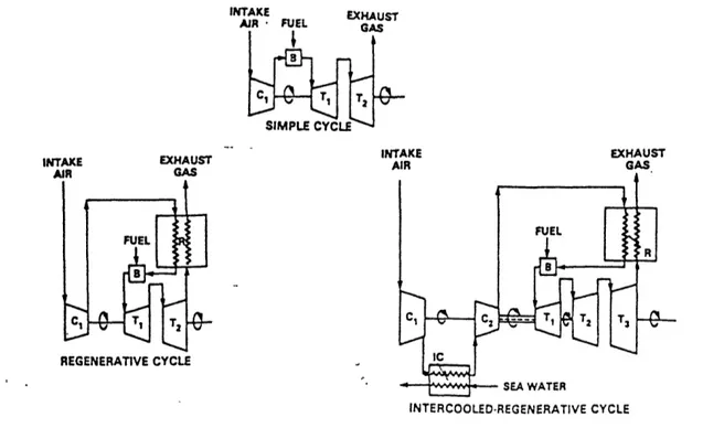
Regenera-tion. Source: Bowen and Groghan [3] ... 16 1-4 Schematic Diagram of Simple, Regenerative and Intercooled-Regenerative
Cycle Configurations. 18
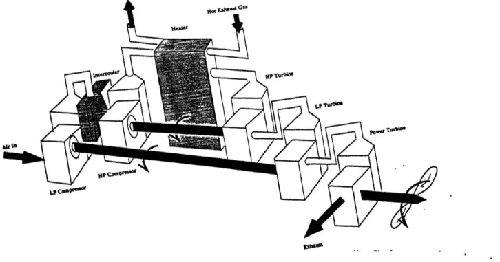
2-1 Air-Bottoming Cycle baseline schematic. The fans Represent the Cooling Effect of Water on the Compressed Air ... . 23
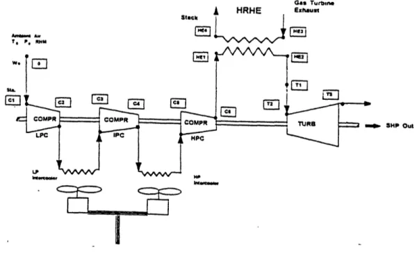
3-1 T-S diagram of the Air-Bottoming Cycle ... 27 3-2 Air-Bottoming Cycle Arrangement Diagram.Notice the LM2500
rep-resented by the flow of hot exhaust gas entering the hot side of the
heater ... 28
3-3 Variation of turbine and compressor isentropic efficiency with pres-sure ratio for polytropic efficiency of 0.85 in each process ... 29 3-4 Air-Bottoming Cycle sensitivity, of percentage of LM2500 power
gen-erated, on compression ratio ... 33 3-5 Air-Bottoming Cycle Horsepower generated at different compression
ratios ... 34
9
3-6 Typical U.S. Navy Destroyer Operating Profile. The figure demon-stratesthe percentage of time spent by a DDG-51 destroyer at various
speeds ... 37
3-7 Typical U.S. Navy Destroyer Power Requirement at Different Speeds. 38 3-8 Air-Bottoming Cycle Efficiency Improvement to the LM2500 ... 39 3-9 Air-Bottoming Cycle Off-Design Performance. ... 39 3-10 The ABC's operation, fit in a DDG-51 operating profile. There is a
significant contribution in the overall power from the air-turbine... 40 3-11 LM2500 Power Supplied as a Function of the Total Power Generated
by the Combined ABC ... 41
4-1 Schematic Diagram of a Compressor's Stages. ... 45 4-2 The effect of finned tubes on the overall heat-transfer coefficient used
in the design of the intercoolers. ... 48 4-3 Heat transfer effectiveness as a function of NTU and capacity-rate
ratio for crossflow exchanger with fluids unmixed. ... 49 4-4 Finned flat tubes, surface 11.32-0.737-SR. ... 50 4-5 "New Best-Fit" Line of Surface 3/16-11.1 with Slope s=0.46 was Used
for the Design of the Heater ... 50
5-1 Adiabatic Head Chart. Compressibility Factor Z=1.0 ... 62 5-2 Frame Selection Chart ... 63 5-3 The Air-Bottoming Cycle has been Considered for Future Marine
Applictions by General Electric also. ... 66 5-4 Typical U.S. Navy Destroyer Operating Profile. ... 69
5-5 Air-Bottoming Cycle sfc Improvement to the LM2500. . . .. 70
5-6 Typical U.S. Navy Destroyer Power Requirement at Different Speeds. 71 5-7 LM2500 Power Supplied as a Function of the Power Generated by
the LM2500+ABC. . . . ... 73
LIST OF FIGURES
List of Tables
3.1 Coefficients for the Cp and hair,T numerical approximations in SI units, reproduced from Wilson [5] ... 30 3.2 Values of key parameters, and initial conditions as used in the
ther-modynamic analysis of the Air-Bottoming Cycle. ... 32 3.3 Design point conditions and configuration parameters ... 36
4.1 Input Parameters to the Design Process, determined in the
Thermo-dynamic Analysis of the ABC. The hot gas conditions used here were the exit conditions of the exhaust gas exiting an LM2500 ... 44 4.2 Assumed Parameters used in the Design Process. ... 46 4.3 Values for the coefficients in equation 4.43 for side one of surface
3/16-11 ... 51
4.4 Reproduced from Table 2 of Campbell [6] incorporating Table A-1 of
Kays and London .... ... ... 52
4.5 Reproduced from Table 3 of Campbell [6] incorporating Table A-8 of Kays and London ... 53 4.6 The Resulting Parameters, and Physical Characteristics of the
Inter-coolers
...
... ..
54
4.7 The Assumed Values for Key Parameters, Input to the Heater's de-sign and the Resulting Heater's Characteristics. ... 56 4.8 The Physical Characteristics of the Air-Bottoming Cycle ... 57
LIST TABLES OF 11~~~~~~~~~~~~~~~~~~~~~~~~~
5.1 The Input Quantities to the Model Used for Fitting the Designed Rotating Components to the Line of Products of a Radial Turboma-chinery Manufacturer ... 62 5.2 The Calculated Quantities for Frame Selection of the Compressors
and the Resulting Models Selected with their Prices. The Frame Size was Used fro the Purpose of estimating the Price and not to Estimate the Size. The Size of each Compressor is Shown here only as a Reference Point. The Prices of the Turbines were Based on the Prices of the Corresponding Compressors ... 65 5.3 The Acquisition Cost of all the Components of the Air Side of the
Air-Bottoming Cycle, Estimated from Three Different Methodologies. 67 5.4 Some Economic and Propulsion Configuration Assumptions Made for
the Calculation of Operating and Life-Cycle Costs ... 68 5.5 Operating Profile and the Cost Saving of the Second Operating
Sce-nario for the ABC Aboard a DDG-51 ... 74 5.6 The Operating and Life-Cycle Cost of the Air-Bottoming Cycle when
installed aboard a DDG-51. The Acquisition Cost used is that devel-oped from General Electric's estimates ... 75
Chapter 1
Introduction
1.1 General
During the early stages of the ship design process, the selection of the propulsion and auxiliary system takes place. Not only these two systems along with the fuel account for a great percentage of the vessel's displacement (forty percent in a sur-face combatant), but also they have a pervasive influence on both acquisition and operating costs as well as the following stages and iterations of the design spiral.
In the past fifty years, the most revolutionary technological advancement for the propulsion of naval ships is perhaps the gas turbine. Navies worldwide have been exploring, developing and adopting the gas turbine as an efficient, cost-effective, reliable prime mover for most combatants. It is the preferred choice for propulsion on most mid-sized naval combatants; future estimates, suggest that by the 21st century almost all U.S. Navy ships will be powered by gas turbines [1].
A significant drawback of gas turbines in naval ships is their poor off-design efficiency, and navy ships spend a significant portion of their operating life at low power levels. So far, and to a large extent, the technology and its development depends on the ability to transfer and to apply processes from the aerospace indus-try. Nevertheless, gas turbine technology has matured so much, that it may not be
Chpe
1.Itoucin1
cost effective to improve a simple cycle by either using exotic materials or advanced manufacturing methods. The gains are relatively small, while the investment can be very significant. On the other hand, a simple cycle can enjoy major improvements, in both performance and operating cost, at design and off-design, by rerouting the flow of the fluids driving the engine and introducing heat transfer. In the past ten years the U.S. Navy engineers have investigated applications of various modifica-tions to the simple cycle, and configuramodifica-tions that will provide more flexibility, higher reliability, while they could be efficient and cost effective. Along the same lines, the Air-Bottoming thermodynamic cycle, patented by William Farrell of General Elec-tric, is presented, analyzed and modeled, demonstrating that waste heat recovery can be an efficient and yet, not an expensive additional source of energy to that of a primary, simple Brayton cycle.
1.2 Background
In the mid-1970's when fuel cost got higher and a because very significant contrib-utor to the life-cycle cost of a combatant. Various programs, that would lead to the design of a more cost effective power plant, were proposed for investigation and development. Along with the rising fuel prices, the commitment of the U.S. Navy to gas turbine propulsion made more attractive the conversion of waste heat into useful shaft power. For a simple gas-cycle engine such as the General Electric LM2500, which is the main propulsor of most mid-sized surface combatants, such a devel-opment program was the design of the RACER (Rankine Cycle Energy Recovery)
system.
In December 1979, the Naval Sea Systems Command awarded contracts to de-velop the conceptual design to provide 25% minimum improvement in ship propul-sion fuel consumption and increase the ship's operating range by 1,000 nautical miles [2]. It was found that a considerable amount of energy could be recovered
Chapter 1. Introduction 14
MODUL
Figure 1-1: RACER modular components and baseline schematic.
and re-used by a waste recovery system using the hot exhaust gases (1000 F). The RACER system was an unfired waste heat recovery system that used the exhaust gases to generate medium pressure steam that can be used as an additional source of energy to the main propulsion unit of the LM2500. Figure 1-1 shows both the schematic and the modular components of the system. By reducing the load on the main propulsor, this configuration was operating as a nonmission critical system and could drive fuel consumption down by 20%. Nevertheless, a steam and gas turbine combined cycle has a number of drawbacks. Steam is a medium much dif-ferent from gas, to contain and handle. The size and technology of the appropriate components that would guarantee the performance and reliability of the cycle, and the purity of the steam increase the costs related to the development, acquisition and operation of such a cycle. Also the fact that heat recovery steam generator is much less responsive to required changes in output than the gas turbine, contributes to the loss of even the most attractive characteristics of the RACER engine. Since
Capter . Introduction
14Chapter 1. Introduction 15~~~~~~~~~~~~~~~~~~~
the Navy requirements asked for minimum weight, compact design and simplicity of the system, non of the existing components was found appropriate for the new engine. Although new components incorporating innovative design were developed, the additional weight and volume of this so called COGAS (Combined Gas and Steam) arrangement, along with the high production costs associated with the high technology components used, did not take the RACER engine much further than
the testing facility.
Since the demand for higher efficiency and lower operating cost continues grow-ing, the U.S. Navy is now looking into other configurations that may have better chance of success than the RACER program and may finally see the light of produc-tion. The unattractive features of RACER along with the low efficiencies demon-strated by the simple gas turbine cycle at part-load conditions, have led towards the development of an intercooled, recuperative gas turbine engine. In this engine, heat from the exhaust gas stream is recovered by a gas-to-air heat exchanger (recu-perator) and preheats the compressed air before it enters into the combustor. By
Figure 1-2: Regenerative cycle's T-S diagram of heat recovery potential.
Chapter 1. Introduction
16doing this, less fuel is required to heat the gas to the turbine inlet temperature. Figure 1-2 shows how regeneration alone reduces the required fuel needed to raise the compressed-air temperature to the combustion inlet temperature. The improve-ment in thermal efficiency due to adding the recuperator to the simple cycle depends on the difference between the exhaust gas temperatures and the compressor exit air temperature, as well as the effectiveness and pressure drop of the recuperator.
Lately, the trend in high end commercial gas turbines is towards higher compres-sion ratios. As comprescompres-sion ratio increases to 18:1 and over, the above temperature
a U a a1= a 03 Z I i I I I / T rv. iiIIIE, I I I
Figure 1-3: Thermal Efficiency
Source: Bowen and Groghan [3]
ES ! U U !
10 Is 3 I 3
COMPeRaON RAIo
Improvements from Intercooling and Regeneration.
I.-.I I I
difference approaches zero and heat transfer is no longer possible. To overcome this obstacle, air-to-air or air-to-water heat exchange is introduced at an intermediate stage of the compression process. This process is called intercooling. Thus, not only
u. T . _
-Chapter 1. Introduction 17 the compressive work is reduced, but also the overall temperature rise across the compressors is lowered. The savings in compressive work can be significant to the performance of a simple cycle engine since two out of every three horsepower gener-ated by the turbine is used in the compression [1]. Recuperating a first-generation marine, simple cycle, gas-turbine can increase the thermal efficiency from the cur-rent 26% to almost 38%, depending on pressure ratio and other factors, while just intercooling can improve the same quantity of the second generation engines from 32% to 34% for the same compression ratio without requiring advances in the basic core engine technology. Intercooling and regeneration together, can take the thermal efficiency of the existing marine gas turbines up to 42%. A graphic repre-sentation of all this is shown in Figure 1-3. The extra weight of the intercooler and regenerator can be off-set a little from the smaller engine-core that an ICR engine requires. The combination of the 30% fuel savings that such an advanced cycle can provide, along with the weight savings associated with the intakes and uptakes, can raise the cycle's power by 35%. The greatest fuel savings come from the off-design fuel consumption improvement, which consumption in the simple cycle is higher by as much as 40% from that of the advanced cycle.
Cost has always been a driving factor of the development of a new engine. In the case of gas turbines the highest cost is that of developing the rotating parts. Much effort was put on adapting existing simple-cycle turbomachine to the regenerative-intercooled configuration. As a result, three alternative core engines were identified which could yield regenerative or intercooled-regenerative gas turbines suitable for propulsion of mid sized surface combatants. These distinct alternatives included:
* Modifying the Rolls Royce Marine Spey which has a dual-spool gas generator to include both an inter-cooler and recuperator.
* Modifying the General Electric F404 dual-spool military turbofan to include both an intercooler and recuperator and incorporating a new-design power
Chapter 1. Introduction 18
turbine to obtain a marine propulsion engine.
* Modifying the high-pressure spool taken from the Pratt & Whitney PW2037 or PW4056 commercial turbofans to include a recuperator and incorporating
a new design power turbine to obtain a marine propulsion engine [3].
Finally, in 1983 contractors studies were initiated and in 1992 Westinghouse Electric Company was awarded the contract as the overall ICR-engine development program coordinator. The core of the new engine is based on the Roll Royce Marine Spey, while Allied Signal Air-Research Company was awarded the development of the intercoolers and the recuperetors of the engine.
INTAKE AIR FUEL INTAKE EXHAUST EXHAUST flh INTAKE AIR EXHAUST GAS REGENERATIVE CYCLE INTERCOOLED-REGENERATIVE CYCLE
Figure 1-4: Schematic Diagram Regenerative Cycle Configurations.
of Simple, Regenerative and
Intercooled-General Electric, having spent the energy in putting together a competitive bid for the ICR engine, decided that they would keep developing their own version of an
Chpe
1.Itoucin1
advanced gas-cycle. The result of this is the regenerative LM2500. It is an engine that as its name suggests, is going to be based on the so-far standard engine for the mid-sized surface combatants, but with regeneration from the exhaust gases pre-heating the compressed air before entering the combustion chamber.
Figure 1-4 shows the conceptual differences between the simple gas turbine cycle, the regenerative cycle and the intercooled-regenerative cycle.
Another potential improvement to gas turbine propulsion of Navy ships is the Air-Bottoming Cycle (ABC), a cycle using air as the working fluid to develop power from the waste heat of the gas turbine. This cycle will be investigated to determine whether it could provide a viable alternative to the ICR engine.
1.3 Thesis Objective
William Farrell of General Electric's Industrial Gas Turbine Division, patented a new conceptual idea of a combined (or advanced) gas turbine cycle. This is the Air-Bottoming Cycle (ABC) or the Farrell Cycle, named after its inventor.
The ABC is a thermodynamic gas-turbine cycle, using unvitiated air as its work-ing fluid, meanwork-ing air that it does not go through a combustion proccess, which is coupled to a simple gas-turbine cycle. The cycle consists of a multi-stage com-pression proccess where the air passes through stages of comcom-pression and cooling. The latter is achieved by the use of intercoolers between two adjacent compression stages. The air before it expands in the turbines, it passes through a heat exchanger that raises the fluid's temperature using the waste heat from the gas turbine. Com-paring this new cycle to its main competitor for the propulsion of Navy ships, the ICR engines it is clear that both engines share similar technologies in respect that
they both use intercooling and regeneration of waste heat from a gas turbine. A study was initiated to investigate the potential of this new cycle in finding applications in the surface combatants. As an initial step towards understanding
20
the benefits of the ABC configuration, the components composing the cycle had to be outlined, while the advantages and improvements to the simple cycle, as well as compared to the rest of the combined gas-turbine cycles had to be identified.
This thesis focuses on evaluating the size, cost, and performance of the ABC system. First, the examination of the thermodynamics will help analyze the Farrell Cycle, and will lead to the selection of a design point. This point will set the basic conditions around which component design will be considered. Modeling the design process and its performance evaluation is one of the tasks that will facilitate future alterations and further investigation of the cycle. The analysis and design process is centered around three computer programs and two spreadsheets. The overall design then gives an efficiency prediction, which along with the off-design performance
defines the overall efficiency and SFC operating envelop of the new engine. This envelop is then coupled to the operating profile of a mid-size surface combatant of the U.S. Navy is used to develop the operating profile of the engine. Finally, the cost of acquiring the engine will be considered, while the operating costs of the unit in a representative Navy ship, such as the DDG-51, will be estimated assuming the ABC is coupled to an LM2500 gas turbine. As a result of the above analysis, it will be determined, whether such a configuration will be not only applicable and efficient, but also cost effective. Starting in the following chapter, the Air-Bottoming cycle is presented and its major components are identified.
As a closing point, this thesis will recommend future areas of investigation in order for the design of the ABC to become more accurate and detailed. To the extent of a first attempt for the design of this new engine, two scenarios are going to be investigated for possible applications in a Navy ship. Further examination of the applicability of the cycle, such as when coupled to an electric drive, will be proposed keeping in mind the weight and volume implications imposed by the Navy
standards.
Chapter 2
The Air-Bottoming Cycle
2.1 An Overview
There are some thermodynamic conversion, or chemical, processes that produce large quantities of hot byproduct gases containing sufficient heat energy to make it
economically attractive to collect and use the heat energy [4]. In the open Brayton cycle's case, this chemical process is the burning of fuel and air in the combustor's chamber, the product is the torque produced, and the byproduct is the heat lost through the exit of the hot exhaust gases. Two out of every three horsepower produced are used to drive the compressors, while the remaining power is available on an output shaft.
The Air-Bottoming cycle provides an air-cycle thermodynamic conversion system in which air is compressed in a multi-stage compression process. Intercoolers are used between each adjacent pair of compressors in order to keep the temperature of the compressed gas almost as low as the ambient temperature before each succeeding compression and make the compression work more efficient. The compressed gas is passed through a heater, where its temperature is raised by the waste heat of the
gas turbine's exhaust gas flowing in the counterflow. As one of the main advantages
and objectives of this combined cycle, the temperature gradient between the heated
Chpe2h
Ai-otmn Cyle2
compressed gas and the cooled exhaust gas is minimized by establishing the two flows such that they both have about equal heat capacities. This minimum gradient is necessary for maximum thermodynamic efficiency of the cycle. Further heat-capture may make use of the effluent heated medium from the intercoolers as well as the exhaust from the turbine [4]. A substantial part of the power produced is used to run the compressors, while any additional expansion of the now hot compressed gas, through a power turbine, can generate power that can be used directly.
There are three main objectives of the Air-Bottoming cycle:
* To provide a combined thermodynamic-cycle system that is coupled to a gas turbine and which has a greater thermodynamic efficiency than the gas turbine alone.
* To retain the operational flexibility and reliability of the gas turbine.
* To employ an air-bottoming cycle for recovering heat energy in a useful form from a stream of heated gas [4].
* To simplify the process for the bottoming cycle.
There are certain functional similarities between the ABC and the ICR, which may be, along with the regenerative gas turbine of General Electric, the main com-petitor of the new engine. Both the ABC and the ICR are concepts conceived to improve the current performance of the gas turbine which is the main propul-sion engine for most mid-sized surface combatants. Both new engines are based on and designed around existing gas-turbine parts. The ABC in this example will be designed around the LM2500, while the ICR's core is based on the Rolls-Royce RB211-535. This is done in order to reduce the development, design and production costs of both new engines. Both engines will use cooling elements (intercoolers) and heat exchangers in order make the power generation more efficient. On the other hand there are some significant differences between the two engines. The combined
Chapter 2. The Air-Bottoming Cycle 23
cycle consists of two turbine modules; the LM2500 unit and the ABC which is the one examined later in this report. The ICR engine is a single integrated unit. Also, the ICR's turbine consists of parts that exists in the industry, while the ABC's air cycle since it is a new part gives some freedom in its design. Thus, in this report radial components have been selected, while William Farrell has approached the design with axial-flow compressors.
Gas Turbn.
j HRHE Exhunu
Stle kj
.,^~~r
" AdE
SHP Out
Figure 2-1: Air-Bottoming Cycle baseline schematic. The fans Represent the Cool-ing Effect of Water on the Compressed Air
For the purposes of this study and for a potential application of this new combined-cycle engine aboard medium-size surface combatants, the General Electric Aircraft Derivative LM2500 Marine Gas Turbine is considered as the source of the hot exhaust gas. In such case, the exhaust gas exits the gas turbine at a temperature of about 1000 degrees F. Furthermore, in the preferred embodiment, the working gas in the compression process, intercooling and expansion through the turbine is
Chapter 2. The Air-Bottoming Cyclee 23
Chapter 2. The Air-Bottoming Cycle 24
atmospheric air. A schematic of this new conceptual combined gas turbine cycle is
shown in Figure 2-1.
In the following chapter, some of the thermodynamic principles and the corre-sponding analysis of the Air-Bottoming Cycle (ABC) will put the base on which the design of the cycle will be developed in Chapter 4.
Chapter 3
Thermodynamic Analysis
3.1 Introduction
The thermodynamic analysis of the Air-Bottoming Cycle (ABC) is based on the analysis of the gas-turbine or Brayton cycle, meaning that the same principles and properties of the working fluids that apply to a simple cycle are used here also. The difference in analyzing the ABC is the addition of three heat exhangers, i.e. two intercoolers and a heater.
The working fluid in the Air-Bottoming cycle is air. More specifically, the air used in the Farrell Cycle is atmospheric air whose oxygen has not been subjected to a combustion process. As described later in this chapter, the combustion process that in most conventional gas-turbine cycles is responsible for raising the thermal energy of the working fluid, is replaced in the ABC by a heating process. Thus, since there is no fuel mixing, it is a valid and a very convenient assumption to treat air as a perfect gas in an initial approach to analyze the cycle.
In the ABC, the compressed air is passed through a heater, where its temperature is raised by the waste heat of the gas-turbine's exhaust gas flowing in the counterflow. For the purpose of this thesis, the General Electric's aircraft-derivative, LM2500, marine gas-turbine, is used as the source, providing the hot exhaust gas. The
Chapter 3. Thermodynamic Analysis 26
LM2500 is chosen for several reasons. Of those, the most dominant ones are the
following two:
* William Farrell, who was the inventor and the first to analyze the ABC, used the LM2500 as his waste heat source. Thus, there is a basis for comparing the results of this research.
* The LM2500 is the most widely used gas-turbine in the U.S. Navy, used as the main propulsor for mid-size surface combatants. Thus, there is a basis for comparing engine performance based on the operational profile of a U.S.
destroyer.
The exit conditions of the hot exhaust gas coming out of the LM2500 are used for the optimization of the Air-Bottoming cycle. Since optimum and off-design performances are well established for this engine when operating on a DDG-51 U.S. Navy destroyer, the use of the LM2500 facilitates the prediction of the target and off-design performance of the ABC.
3.2 Thermodynamic Analysis of the ABC
The Air-Bottoming cycle provides an air-cycle thermodynamic conversion system in which air is compressed in a multi-stage compression process. Starting from the first compression stage, ambient air is compressed by a pre-determined ratio (2:1 will be used later). With compression, the temperature of the air is increased along the first near vertical line of the T-s diagram describing the thermodynamics of the cycle, shown in Figure 3-1. The compression process is nearly adiabatic. Intercoolers are used between each adjacent pair of compressors, in order to keep the temperature of the compressed air low before each succeeding compression, and make the compression-work more efficient. The compressed air is passed through a heater, where its temperature is raised by the waste heat recovered from the
Chapter 3. Thermodynamic Analysis 27
hot gas-turbine's exhaust gas flowing in the heat exchanger's counterflow. The hot compressed air is then expanded in the turbine to develop the power of the cycle.
As one of the main advantages and objectives of this combined cycle, the tem-perature difference between the heated compressed gas and the cooled exhaust gas is maintained in minimum by establishing the two flows such that they both have about equal heat capacities. This minimum gradient is necessary for maximum thermodynamic efficiency of the cycle. Further heat-capture may make use of the heated coolant from the intercoolers as well as the exhaust from the turbine [4]. A substantial part of the power produced is used to run the compressors, while any additional expansion of the now hot compressed gas, through a power turbine, can generate power that can be used directly.
Gas Turbine Exhaust Temp. Ambient Temperature T I !, z -1 I, S
Figure 3-1: T-S diagram of the Air-Bottoming Cycle.
In the thermodynamic analysis of the ABC there are some assumptions that need to be understood. These assumptions are necessary in order to take into account differences in the performance of real cycles from that of ideal ones. In performing cycle calculations, values of both the compressor and the turbine efficiencies need to
I
Chpe .TemdnmcAa ss2
be assumed. Because turbomachines are essentially adiabatic, the ideal process is isentropic. Thus, isentropic efficiencies may be used. Nevertheless when performing cycle calculations covering a range of pressure ratios, in order to determine the opti-mum pressure ratio for a particular application, polytropic efficiency, 7pc, should be used. It is found that compressor isentropic efficiency tends to decrease and turbine
H Esh. Uf Gas "•• e". HP by WoXr ' D 11r I WI? JCO
L?9C
Figure 3-2: Air-Bottoming Cycle Arrangement Diagram.Notice the LM2500 repre-sented by the flow of hot exhaust gas entering the hot side of the heater.
isentropic efficiency to increase as the pressure ratio, for which the compressor and the turbine are designed, increases [5. Figure 3-3 shows how turbine and compres-sor isentropic efficiency varies with pressure ratio for a given polytropic efficiency. Assuming that compression and expansion consist of (n) stages, whose pressure
Chapter 3. Thermodynamic Analysis 29
ference tends each to zero, the polytropic efficiency is the isentropic efficiency of an element stage in the process, such that it is constant throughout the whole process. For this analysis of the ABC, the polytropic efficiency was set to 0.88 for the com-pression and 0.92 for the expansion. These values were used because it is assumed the compressors would be large and well designed.
Figure 3-3: Variation of turbine and compressor isentropic efficiency with pressure ratio for polytropic efficiency of 0.85 in each process.
In this cycle analysis both (cp) and (h) are calculated based on the Chapell and Cochshutt 'approximation. Knowing that (cp) is a function of temperature, they were able to approximate its value by using the following polynomial:
lIn 1974, Chapell and Cockshutt developed these sets of polynomials and their coefficients for generating thermodynamic data by computational methods, as part of a work initiated by the National Research Council of Canada. The data and the polynomials are based on the treatment of dry air and combustion products as semi-perfect gases, so that the specific heat, enthalpy and entropy are dependent solely on temperature and are independent of pressure. Wilson got permission to reproduce the values of these coefficients and with the help of R. Bjorge he presented them in SI units in his book, from which they are extracted and presented in Table 3-1 of this thesis. I I I I I I I I i I I I I I I I I - L~ I I I I I I I I I I I I I i I I I I I I ,J--I ,I I I I~,-, I I I I I I I I I I I I a I a I I I I I 11- q *11 90 85 80 75 Turbine Compressor 2 4 6 8 10 12 14 Pressure ratio r
Chpe
.Temdyai nlss3
Cp(T) = E Ci T' (3.1)
i=O
The coefficients of the polynomial are constants, with units of (J/kg) and their values are shown in Table 3.1.2 Enthalpy of dry air, at T-Kelvin, is approximated by a similar polynomial,
C Ti+l
hair,T
E
i T+'+CH
(3.2)
i=O (i+1)
In the latter polynomial, CH is another constant coefficient whose value also appears in Table 3.1. T (K) Symbol Co C1 C2 C3 C4 C5 CH CF 200-800 800-2200
(J/kg)
(J/kg)
+1.0189134E+03 +7.9865509E+02 -1.3783636E-01 +5.3392159E-01 +1.9843397E-04 -2.2881694E-04 +4.2399242E-07 +3.7420857E-08 -3.7632489E-10 0.00E+00 0.0 0.0 -1.6984633E+03 +4.7384653E+04 +3.2050096E+00 +7.0344726E+00Table 3.1: Coefficients for the Cp and hair,T numerical approximations in SI units, reproduced from Wilson [5].
When the air exits a compressor, it enters an intercooler after one or more com-pression stages or the heater after the final comcom-pression stage. The air goes through an almost isobaric temperature change. The inlet temperatures of the compressed air are known for all stages of heat exchanging; either that of cooling (two stages of intercooling used in this thesis) or that of heating. Also, the inlet temperatures of
2
Wilson D. G., The Design of High-Efficiency Turbomachinery and Gas Turbines, The MIT Press, June 1992.
Temperature Range
. w . .
Chapter 3. Thermodynamic Analysis 31
the cooling water in the intercoolers and the hot gases in the heat exchangers are known. The only temperatures to be determined are the exit temperatures of the compressed air coming out from the intercoolers and before it enters the turbine. To determine these temperatures the heater's effectiveness is defined as,
heater - (Tairot - Tair,in)
(33)
(Texhaust,in - Tair,in)where the temperatures with the subscript (air), indicate the (in)let and (out)let
temperatures of the cold, compressed air. In the same manner, the subscript
(exhaust), indicates the corresponding temperatures of the hot gases exiting the gas
turbine (in this case the LM2500). For the intercoolers, the effectiveness is given a coresponding equation:
fintercooler airinTairout) (3.4) (Tairin - Twater,in)
For the analysis of the ABC, the effectiveness of the intercoolers is 77.1%, while the effectiveness of the heater is 91.1%.
Table 3.2 summarizes all the assumed values of the key parameters used in the analysis of the ABC, as well as the initial conditions.
The need for size minimization, in terms of both volume and weight, that is required by any application developed- for a Naval Combatant, led to the optimiza-tion of the heater's size without any sacrifice in performance. Campbell [6], in 1989, worked on the Soland modification of the' Keys and London way of presenting heat exchanger performance. This new method minimizes the volume of the core of a plate-finned heat exchanger. A detailed description of this method, that led to the final design of the heater, is presented in the following chapter.
Compactness is one of the major reasons that made radial machines attractive for the design of the ABC-engine in this thesis. Radial-flow compressors can be designed for a higher per stage pressure ratio, enthalpy rise or size of head developed,
32
than their equivalent axial machines. Nevertheless, the efficiency of radial-flow machines is relatively lower than that of an equivalent axial-flow machine. Flow separation, resulting from the compex three-dimensional flow in the rotor, the fact that much of the enthalpy rise can be attributed to the velocity head, relatively low radial-diffuser pressure-rise coefficients, and higher friction developed from the larger wetted surfaces are the four dominant reasons for the difference in the efficiency between radial and axial machines.
If Symbol Compressors Turbines 11
77pc i 0.88 0.92 __ - Intercoolers Heater
Je
0.771 0.911 Air In Water In T (K) 288: 288. 15 P (kPa) 100.33Table 3.2: Values of key parameters, and initial conditions as used in the thermo-dynamic analysis of the Air-Bottoming Cycle.
One other factor that contributed to the selection of radial components for the design of the Air-Bottoming Cycle is the required ducting necessary to collect and pass the flow to the intercoolers and the heater. Radial machines, have already incorporated in their design the flow collection and carry the appropriate ducting. While this complication in the design of radial machines may seem to be disadvan-tegeous (due to the pressure losses) and cost ineffective for any other application, in the case of this intercooled-regenerative cycle it turns out to be very attractive. The additional ducting and flow collecting components for an axial machine will tend to increase both size and cost further. It should be clear that the requirement of lower volume, weight and cost place some very rigid design constraints.
Finally, the fact that William Farrell was approaching the design of the ABC engine using axial components for industrial applications, made the design of a
Chapter 3. Thermodynamic Analysis 33
radial version of the engine attractive for comparison.
Thus, all the key parameters necessary for the thermodynamic analysis of the cycle have been determined. In the following section the Air-Bottoming Cycle's
analysis results are presented with a simple sensitivity study that will support the
reasoning behind the selection of the engine's design point.
3.3 Air-Bottoming Cycle Analysis Results
Three computer programs were developed in order to model and solve both the thermodynamics and the design of the Air-Bottoming Cycle. The programs are kept simple and are based on the theory and design principles outlined in the previ-ous sections, as well as in the following chapter. All programs are interactive in the sense that they give the user the freedom to define most key parameters. Many
con-Air Turbine's Power as % ofLM2S00 30 25 20 15 10 54
I---'-- i7- i i i
i--I
*
a
a---L---___
_
_e
A
I .. '° I ~ I 'Z ... ~~~~'- L ._____ _-.._.________ L_...__.... ... --,---n---~r--- --' f- I~~ i , ' ..~ - ' '. ...- -~ -: --. -... .-_ -,z -_-- --I I I I I , ~ ~ ~ ~ ~ ~ ~ ~~~~~~~~~~ I i I I i ' , i , ~ , , I I I\ I I l I I (\ I I ! I I I I ' I '- I\ I I i _ I- I I I I ! I I I I I t I I I I a 2 4 6Compressor Pressure Rado r
8 10 12 14
Figure 3-4: Air-Bottoming Cycle sensitivity, of percentage of LM2500 power gener-ated, on compression ratio.
Chapter 3. Thermodynamic Analysis 34
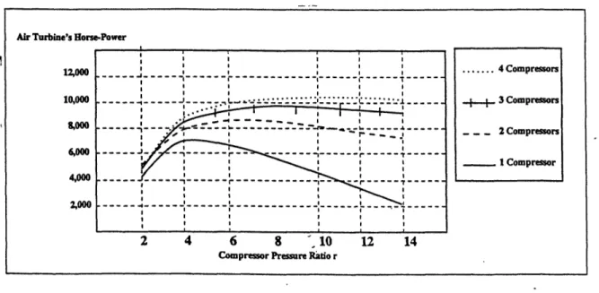
figurations can be investigated and the new air cycle can consist of various number of compressors, intercoolers and turbines with different performance characteristics. In this manner, one compressor with a compression ratio of 8:1, can be substituted by three compressors each having a compression ratio of 2:1. The selection of the optimum configuration and design point was performed in such an iterative fashion. The sensitivity of the performance of the ABC to parameters like the number of the compressors and their individual compression ratios is shown in Figures 3-4 and 3-5. Furthermore, the user/designer can change the inlet conditions to the heater model, which means changing the source of the hot exhaust gas. The air side of the Air-Bottoming Cycle can be re-designed and coupled to various gas-turbines. Thus, many more potential applications of the new cycle can be found, since not all possible applications use the General Electric LM2500 gas turbine.
Air Turbine's Horse-Power
;1 i a I I I I~~~~~~~~~~~~~~~~~~~~~~~~~~~~~~~~~~~~~~~' ! I I I I! I I I a ... 4 '-- -- '--9 t .I W II - I - - - ---I '-- _^ I , I ; I wI,,
* -.,rE,-
I .~--
a
I . . ' .--
.-,--,
a a a
.' /L
--
. I. I~~~~~~~~~~~~~~~~~~~~~~~~~~~~~~~~~~ (/ ! !I , I f/ , !I I , I~ ~ ~
~~ ~~ ~ ~~~~~~~~~~
\ 1 I I I ' I I I ! I I a…-… I I ! I I a I a I I ... a a a, a 2 4 6 8 ' 10 12 14Compressor Pressure Ratio r
Figure 3-5: Air-Bottoming Cycle Horsepower generated at different compression ratios. 12,000 10,000 3,000 4,000 2,000 ... 4 Compressors 1 3 Compressors -_ 2 Compressors I 1Compressor
Chapter 3. Thermodynamic Analysis 35
Two of the computer programs used for the analysis of the Air-Bottoming Cycle (ABC) are concerned with the design parameters and will be addressed after the design principles have been outlined in the next chapter. The first program provides the thermodynamic analysis. The model can run with either the desired tempera-tures of each stage, or the pressure ratios being known. Although only the second option of the code is the one used for the purpose of this thesis, freedom to repeat the overall process in a much easier and faster way was the philosophy behind the development of the code. Whatever path the user decides to follow, the program will use the input parameters to determine the remaining design conditions that describe each stage sufficiently. The program will run for as many compressor stages as spec-ified in the thermodynamics modeling. For the purpose of this thesis, a variation of both the number of compressors in the air-cycle, and the compression ratio of each, was analyzed, in order to decide the final cycle configuration. A configuration of three compressors at a pressure ratio of 2.0 each, is a valid trade-off design point. Although slightly better performance could be achieved with four compressors with an overall pressure ratio of ten, Figure 3-4 shows that there would be an small gain of an additional one or two percent in horsepower. While the horsepower of the selected design point is 9,700 HP, the horsepower of the more complicated engine would only rise to 10,400 HP. Such an engine would be much bigger, heavier and more expensive. Figures 3-4 and 3-5, present the sensitivity study that led to the design-point selection with a configuration of three compressors at a 2:1 compres-sion ratio each. As shown in both graphs,jthe air-cycle's performance, when coupled to an LM2500 operating at design point, is close to the maximum. As shown in Table 3.3, the initial conditions are T = 288.15 K and P = 100.33 kPa. The air, with a mass flow rate of 69.8 Kg/sec, after passing through the cycle will deliver
9,698.2 HP.
Chapter 3. Thermodynamic Analysis 36
LP Compressor Inlet Conditions Exit Conditions
T (K) 288.15 359.5
P (kPa) 100.33 200.66
Air-Flow Rates 69.8 kg/sec 119,777 cfm
Pressure Ratio r 2:1
l
1 t Intercooler Inlet Conditions Exit Conditions
T (K) 359.5 304.5
P (kPa) 200.66 196.7
MP Compressor Inlet Conditions Exit Conditions
T (K) 304.5 379.8
P (kPa) 196.7 393.3
Mass Flow Rate 69.8 kg/sec 59,888.5 cfm
Pressure Ratio r 2:1
2nd Intercooler Inlet Conditions Exit Conditions
T (K) 379.8 309.1
P (kPa) 393.3 385.4
HP Compressor Inlet Conditions Exit Conditions
T (K) 309.1 385.6
P (kPa) 385.4 770.9
Mass Flow Rate 69.8 kg/sec 29,944.25 cfm
Pressure Ratio r 2:1
Heater Inlet Conditions Exit Conditions
TAir (K) 385.6 797.8
PA, (kPa) 770.9 740.3
HP Turbine Inlet Conditions Exit Conditions
T (K) 797.8 720.8
P (kPa) 740.3 542.4
MP Turbine Inlet Conditions Exit Conditions
T (K) 720.8 645.
P (kPa) 542.4 385.7
LP Turbine .Inlet Conditions Exit Conditions
T (K) 645. 573.3
P (kPa) 385.7 268.7
Power Turbine Inlet Conditions Exit Conditions
T (K) 573.3 485.3
P (kPa) 268.7 101.2
Power Turbine's Power Generated 9,698.2 HP
Table 3.3: Design point conditions and configuration parameters.
Chapter 3. Thermodynamic Analysis 37
3.4 Off-Design Performance
Power-plants aboard Naval combatants are usually selected based on a maximum horsepower requirement. Nevertheless, surface combatants spend most of their cruis-ing time at power levels significantly lower than maximum. The representative oper-ating profile of a DDG-51, is shown in Figure 3-6 [71. The operoper-ating profile indicates the need for an engine that not only can meet the maximum speed requirement, but can also perform efficiently at lower speeds. As shown in Figure 3-7, the engines
Figure 3-6: Typical U.S. Navy Destroyer Operating Profile. The figure demonstrat-esthe percentage of time spent by a DDG-51 destroyer at various speeds.
aboard a surface combatant operate a very broad power range. A significant draw-back of gas turbines in Navy ships is their poor off-design performance, increasing their already high, operating cost. Although several modifications have improved the simple-cycle's performance, gas-turbine technology has matured so much, that it may not be cost effective to improve a simple-cycle engine by either using exotic
Chapter 3. Thermodynamic Analysis 37
21
c .,
1..
Chapter 3. Thermodynamic Analysis 38
materials or advanced manufacturing methods. Still, gas turbines perform poorly, when operating at off-design power levels Figure 3-8.
Rerouting the flow is the only way that can bring improvements to the
perfor-mance of a simple gas turbine at a reasonable cost. Cost considerations will be addressed in a later chapter of this thesis. Figure 3-8 shows that by using the ex-haust gas of an LM2500 in the Air-Bottoming Cycle, the off-design performance
of the combined cycle is considerably better. As Figure 3-9 shows, the off-design
28 27 20 23 24 23 20 19 la 1 15 11 1 ICII !I o O100 22000 30B000 '0C00 000 00000 o0000 SHE
Figure 3-7: Typical U.S. Navy Destroyer Power Requirement at Different Speeds.
performance of the new cycle [81 demonstrates even greater contributions to the power of the LM2500. Especially at the lower rating levels, where gas turbines run very inefficiently, there is significant improvement in the power generated. There is 100% additional power provided by the air-turbine when the LM2500 generates 1,000 HP. At the 3,000 HP level of the LM2500, the ABC generates 1,554 HP or an additional 50%. The improvement becomes almost constant after the 10,000 HP
" ·ii i "" i I' :i, i: I-ii I' ; -I1:.r.-,. 11 1 ' ';1 iI.. i-, i 1 .-.-iI r i-.--: i ·- ·-;I: ; "- r t '5. · : I:i j : · I:· ;r. i`I 4 ;r u j I : : i i I ·I; ;· : j -i I ii : · f- ' - · : : ·; i · : : -- i·
1
i 1 i-i i-i I iII; ' i 1 ·,I d · I L r - I: '· : I·rii i r + I,.
.: gi..
. ..- 'I)·. r ; · :t r J- -i e I:
: : 51:· 3-" 'L Irit
Z-.
r ';- - I r L: .1... .s i: i i··': 3' I 'i rI
ir j i `:i i ' II ' - .Chapter 3. 0.6 11 0.5 Thermodynamic Analysis 1M2500. Tr ABC +LN2S00 0 5000 10000 15000 20000 25000 30000 LU2500SHP
Figure 3-8: Air-Bottoming Cycle Efficiency Improvement to the LM2500.
4'.uuI 40000 SHP 35000 30000 25000 20000 15000 10000 5000 . - Air-Turbine,SHP - ABC+LM2500 0 5000 10000 15000 20000 25000 30000 LM2500-SHP
Figure 3-9: Air-Bottoming Cycle Off-Design Performance.
39 0.4 0.3 0.2 0.1 0.0 I I · 1.. I 1 I · r -i con _ v L
---Chapter 3. Thermodynamic Analysis 40
rating of the LM2500, with an average of 32% additional power. Thus, the
operat-7r .1 a, . 64 I, I'S I'41. 'I I 4 1: HP
Figure 3-10: The ABC's operation, fit in a DDG-51 operating profile. There is a significant contribution in the overall power from the air-turbine.
ing profile of the LM2500 will change significantly as shown in Figure 3-10, where the power levels of the ABC are shown against the operating speed of a U.S. Navy DDG-51.
From Figure 3-11 it can be seen that the air-turbine's SHP contribution to the
overall ABC's shaft-horsepower is significant. The power required by the LM2500 is now lowered, and can be described as a function of the total power generated by the combined (ABC) cycle as follows:
SHP(LM25o0) = 0.78904 SHP(L2500o+ABC) - 514.134 (3.5) This relationship gives the magnitude of the power improvement, as the LN12500's
SHP contribution to the overall combined cycle's SHP, at the various horsepower __
Chapter 3. Thermodynamic Analysis 41~~~~~~~
requirements. The significance of such a change in power generated by the LM2500 is demonstrated in Figure 3-10, from where it is clear that for a large amount of
the cruising time of a surface combatant, the air-turbine will contribute a major
part of the overall power. There are similar improvements in the efficiency of the new combined-cycle engine. Both in trends and in magnitude, the efficiency of the Air-Bottoming cycle improves the performance of the new combined engine. Improvement ranges between 97% at the lower LM2500 ratings to 29% at 29,000 HP. The new efficiency curve, as shown in Figure 3-8, ranges between 18% and 47%.
LM2
37189
Figure 3-11: LM2500 Power Supplied as a Function by the Combined ABC.
of the Total Power Generated
In the next chapter the design principles will incorporate the thermodynamics analysis results, in order to generate a design of the new components of the Air-Bottoming Cycle (ABC) and the results of the computer-code, modeling the design, will appear in the final section.
30000 25000 20000 1500( 1000( 50C 00-SHP
Chapter 3. Thermodynamic Analysis 41
Chapter 4
Design Process
4.1 Introduction
The Air-Bottoming Cycle (ABC) was described in the previous chapter and the selected cycle had three compressors of 2:1 pressure ratio each. Also, between each pair of adjacent compressors, intercoolers reduce the temperature of the compressed
air. The compressed air exiting the third compressor enters a heater, where the
compressed air is heated from the waste heat recovered from thew exhaust gas of an LM2500. The air leaving the heater passes through three turbines, each one coupled to a corresponding compressor, before it expands in a power turbine which delivers the power from the ABC. The design goal is to optimize each component
(stage) of the new cycle for maximum output and efficiency and minimum cost. Understanding these constraints and knowing the conditions of the working fluids at all stages, one can move toward a preliminary design of the components of the
Air-Bottoming Cycle.
In this chapter the goal is to match the engine-components to the operating conditions and the power requirements determined by the thermodynamic analysis of the cycle. There were two areas that the design focused on:
Chpe 4. DeinPoes4
* The preliminary design of all rotating parts in two groups of components:
- The design of the compressors.
- The design of the turbines.
* The design of the heat exchangers:
- The design of the intercoolers.
- The design of the heater.
A new engine is attractive for production, not only when it generates signif-icant performance improvement compared to the existing ones, but also when it is cost effective compared to the competition. Both performance and cost charac-teristics have to be taken into consideration, in order to evaluate the potential of the combined gas turbine and Air-Bottoming Cycle to replace simple gas turbines aboard Navy vessels, such as the LM2500, and to compete with other engines under development, such as the ICR engine. The performance characteristics were pre-sented in the previous chapter, while cost will be addressed in the following one. This chapter serves as the transition stage from the performance characteristics of
the air-turbine to the cost evaluation of the combined gas turbine engine and
Air-Bottoming Cycle through the preliminary design of the air-turbine's components. The design-characteristics of the componentsof the new engine will facilitate the estimation of the acquisition cost of the air-turbine and thus the combined ABC, while the performance characteristics will-.be used to address the issue of operating and life-cycle costs.
The input parameters to the design process have been partially determined in the thermodynamic analysis as it was shown in Table 3.3. Table 4.1 summarizes the setup parameters of this design. Each component is designed to match and perform according to these values and some key assumptions, which are being outlined in
Chapte 4.DsgPoes4
Table 4.2. Radial components are used throughout this design, for the reasons outlined in the foregoing chapter.
Configuration Parameters
Number of Compressors 3 Stage Pressure Ratio r 2:1 Number of Intercoolers 2 Intercooler Effectiveness e 0.771
Number of Heaters 1 Heater Effectiveness e 0.911 Ambient-Air T (K) 288.15 Gas-Turbine Exhaust Gas T (K) 838.1
Table 4.1: Input Parameters to the Design Process, determined in the Thermo-dynamic Analysis of the ABC. The hot gas conditions used here were the exit conditions of the exhaust gas exiting an LM2500.
4.2 The Design of the Rotating Components
In the Air-Bottoming Cycle the use of the intercoolers and the heater require the collection of the flow after it exits each compressor. The advantage of using radial components versus using their axial equivalent is that the former collect the flow
in their non-rotating parts, while the latter need additional ducting which in turn
produce further losses.
The preliminary design of all rotating parts of the Air-Bottoming Cycle was therefore based on design principles of radial turbomachines. The methodology
used, breaks the compression and the expansion processes into smaller stages cor-responding to the various parts of the compressor or turbine. Figure 4-1 shows in a schematic form the stages through which the air passes during the compression process. First it enters the first impeller at ambient conditions (Stage 1). Before the design of the impeller could start, the rotational speed will have to be determined.
Chapter 4. Design Process 45
i b -b3 'FUSER
D VANELESS
OUTFLOW
Figure 4-1: Schematic Diagram of a Compressor's Stages.
The rotational speed of the impeller can be calculated by assuming a value of the specific speed. Specific speed is a non diamensional group based on the rotational speed, the volumetric flow rate and the enthalpy rise developed. The volumetric flow rate can be determined from the mass flow rate:
m
Pol (4.1)
For the purpose of this design, the mass flow rate was assumed to be 69.8 k i as determined in Chapter 3. It should be noted that the subscript () indicates stagnation conditions. Specific speed for radial turbomachinary is usually between 0.08 and 0.17. The selection of the appropriate value for the specific speed of a
machine is important, since there is a dependence of the machine's efficiency on the specific speed of the impeller. In this design, the specific speed of the compressor was selected to be 0.12. Thus, by using the following equation the rotational speed
Capter 4. Design Process 45
I
-. 4 --Chapter 4. Design Process 46
of each stage compressor (turbine) can be calculated:
N = N. 60 (h 2- ho).75 1
(4.2)
QO-.
The selection of specific speed in this case is a compromise between N for the compressor and the turbine on the same shaft. In addition, the same specific speed was selected for the three compressors.
Table 4.2 shows all the parameters used in the design of the turbomachinery for the Air-Bottoming Cycle.
The approximate dimension of the complete compressor, i.e. maximum diameter, was estimated to be twice the impeller diameter.
Symbol Compressor Turbine
Mass-Flow Rate (Kg/sec) 69.8 69.8
Specific Speed N, 0.08 Calculated 0.10-0.15 Polytropic Efficiency r/pc 0.88 0.92
Impeller-Blades Zc 12 _ 18
Isentropic Efficiency Ir 0.87 0.92
~~~~~~~~....
Table 4.2: Assumed Parameters used in the Design Process.
4.3 The Design of the Heat Exchangers
For the design of the intercoolers the NTU method of designing one- pass cross-flow heat exchangers was employed. The intercoolers were treated as finned-tube heat exchangers with water flowing on the cold side and hot, compressed air on the hot side. After determining the inlet and exit temperatures, the Reynold's and Stanton numbers need to be calculated. The friction factors now can be found, which in


![Table 3.1: Coefficients for the Cp and hair,T numerical approximations in SI units, reproduced from Wilson [5].](https://thumb-eu.123doks.com/thumbv2/123doknet/13950790.452305/30.918.252.635.583.824/table-coefficients-hair-numerical-approximations-units-reproduced-wilson.webp)