Publisher’s version / Version de l'éditeur:
Vous avez des questions? Nous pouvons vous aider. Pour communiquer directement avec un auteur, consultez la première page de la revue dans laquelle son article a été publié afin de trouver ses coordonnées. Si vous n’arrivez pas à les repérer, communiquez avec nous à PublicationsArchive-ArchivesPublications@nrc-cnrc.gc.ca.
Questions? Contact the NRC Publications Archive team at
PublicationsArchive-ArchivesPublications@nrc-cnrc.gc.ca. If you wish to email the authors directly, please see the first page of the publication for their contact information.
https://publications-cnrc.canada.ca/fra/droits
L’accès à ce site Web et l’utilisation de son contenu sont assujettis aux conditions présentées dans le site LISEZ CES CONDITIONS ATTENTIVEMENT AVANT D’UTILISER CE SITE WEB.
CSCE 2008 Annual Conference: [Proceedings], p. 10, 2008-06-10
READ THESE TERMS AND CONDITIONS CAREFULLY BEFORE USING THIS WEBSITE.
https://nrc-publications.canada.ca/eng/copyright
NRC Publications Archive Record / Notice des Archives des publications du CNRC :
https://nrc-publications.canada.ca/eng/view/object/?id=d898d480-be80-4dbe-a341-b18668783d92 https://publications-cnrc.canada.ca/fra/voir/objet/?id=d898d480-be80-4dbe-a341-b18668783d92
NRC Publications Archive
Archives des publications du CNRC
This publication could be one of several versions: author’s original, accepted manuscript or the publisher’s version. / La version de cette publication peut être l’une des suivantes : la version prépublication de l’auteur, la version acceptée du manuscrit ou la version de l’éditeur.
Access and use of this website and the material on it are subject to the Terms and Conditions set forth at
Experimental study of influence of synthetic fibres on behaviour of
cylindrical high-strength concrete columns
http://irc.nrc-cnrc.gc.ca
Ex pe rim e nt a l st udy of influe nc e of synt he t ic
fibre s on be haviour of cylindric a l
high-st re ngt h c onc re t e c olum ns
N R C C - 5 0 3 1 0
C u s s o n , D . ; D j u m b o n g , A . ; P a u l t r e , P .
J u n e 2 0 0 8
A version of this document is published in / Une version de ce document se trouve dans:
CSCE 2008 Annual Conference Structural Specialty, Quebec City, QC. June
10-13, 2008), pp. 10
The material in this document is covered by the provisions of the Copyright Act, by Canadian laws, policies, regulations and international agreements. Such provisions serve to identify the information source and, in specific instances, to prohibit reproduction of materials without written permission. For more information visit http://laws.justice.gc.ca/en/showtdm/cs/C-42
Les renseignements dans ce document sont protégés par la Loi sur le droit d'auteur, par les lois, les politiques et les règlements du Canada et des accords internationaux. Ces dispositions permettent d'identifier la source de l'information et, dans certains cas, d'interdire la copie de documents sans permission écrite. Pour obtenir de plus amples renseignements : http://lois.justice.gc.ca/fr/showtdm/cs/C-42
Experimental Study of Influence of Synthetic Fibres on
Behaviour of Cylindrical High-Strength Concrete Columns
Alexis Djumbong1, Daniel Cusson2, and Patrick Paultre1
1
University of Sherbrooke, Department of Civil Engineering, Sherbrooke, QC J1K 2R1, Canada
2
National Research Council Canada, Institute for Research in Construction, Ottawa, ON K1A 0R6, Canada
ABSTRACT: This paper presents an experimental study of the behaviour of fibre-reinforced high-strength
concrete columns under concentric loading. Twelve cylindrical columns having a length of 1400 mm and a diameter of 300 mm were built using concrete containing different volumes of synthetic fibres. The effects of the amount of synthetic fibres, amount of transverse reinforcement, and concrete compressive strength on the load-carrying behaviour of confined concrete columns were investigated. The results showed that the use of synthetic fibres can help the confining reinforcement to increase the peak strength and deformation of confined concrete. In particular, the use of up to 1% synthetic fibres by volume of concrete increased the load and strain at concrete spalling by 3% and 17%, respectively, when compared to identical concrete columns without fibres. This same addition of synthetic fibres resulted in an increase in the maximum confined concrete strength and corresponding strain by 16% and 29%, respectively. Under very large concrete deformations, however, the synthetic fibres did not significantly influence the post-peak behaviour of these concrete columns. It is concluded that the use of synthetic fibres in high-strength concrete columns allows the columns to reach their ultimate load capacities with lower risks of premature spalling of the concrete cover, thus improving column durability and helping the confining steel to further increase the strength and ductility of confined concrete, especially in seismic areas.
1. INTRODUCTION
High-strength concrete (HSC) is a brittle material; however, when it is confined with closely-spaced transverse reinforcement, the ductility of HSC structures in seismic areas can be substantially improved (Nagashima et al. 1992). In HSC columns with large quantities of transverse reinforcement, however, spalling of the concrete cover may occur prematurely due to the formation of a weakness plane between the unconfined cover and the confined core, thus temporarily reducing the load-carrying capacity of the column before the lateral confinement can actually increase it later under large deformations (Cusson and Paultre 1994). The use of steel fibres in HSC columns was investigated by Langlois and Paultre (2002). They showed that heavily-confined HSC columns can reach their ultimate load-carrying capacities with fibre contents as low as 0.25% by volume, by providing a gradual load transfer from the concrete cover section to the column core during the spalling of the cover. The effectiveness of steel fibres in confined HSC columns has been recognised recently, resulting in the development of confinement models that account for the effect of fibres on the stress-strain behaviour of confined concrete (Campione 2002). These confinement models, however, are mostly based on load tests conducted on small concrete cylinders (100x200 mm) using steel fibres. Thus, there is a need to test fibre-reinforced HSC columns of large dimensions, especially with non-metallic fibres. The general objective of the present study is to obtain experimental data for the improvement of existing confinement models.
2. TEST PROGRAM
This paper presents an experimental study of the load-carrying behaviour and ductility of cylindrical columns made with fibre-reinforced high-strength concrete. Twelve large-size column specimens were built with a length of 1400 mm and a diameter of 300 mm. Six specimens had a concrete compressive strength of 50 MPa and the six others with a strength of 80 MPa. The test variables studied in this program were: (i) concrete compressive strength, (ii) amount of transverse reinforcement, and (iii) amount of synthetic fibres.
2.1 Column specimens
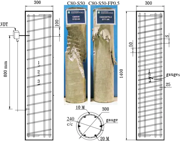
Figure 1 provides the details of the test specimens along with their instrumentation. Each circular specimen was reinforced with six 20-mm longitudinal bars, providing a steel cross-sectional area of 1800 mm2, and spiral transverse reinforcement with a vertical spacing of either 50 mm or 100 mm. The concrete cover thickness over the transverse reinforcement was 25 mm, which was 2.5 times the maximum aggregate size. This geometry provided a total concrete cross-sectional area of 68,890 mm2, and core concrete cross-sectional area of 43,440 mm2. The transverse reinforcement of the six columns with the 50-mm spacing was calculated to meet the CSA A23.3 (2004) requirements for non-seismic design. The spacing of the other six column specimens were doubled (s = 100 mm) with the intent of verifying if the addition of synthetic fibres could compensate for the increase in spiral spacing, i.e. by comparing the load-carrying behaviour of: (i) fibre-reinforced HSC columns confined with 100-mm spaced spirals to (ii) plain HSC columns confined with 50-mm spaced spirals.
C80-S50 C80-S50-FP0.5
s
240
c/c
The transverse reinforcement deformation was measured by electrical-resistance strain gauges installed on the spiral at mid-height, as shown in Figure 1. The axial displacement of each column specimen was recorded using four linear variable differential transducers (LVDT) distributed evenly around the specimen and attached to steel collars clamped to the specimen providing a gauge length of 800 mm. During the test, the recorded data from gauges and transducers and the corresponding axial load obtained from the hydraulic testing machine were fed to a data acquisition system.
The column specimens were loaded on a rigid hydraulic testing machine with load-controlled capabilities, having a maximum compressive load capacity of 6,700 kN. Computer readings were taken at equal load intervals during the elastic response. During the post-elastic response, frequent readings were taken until the transverse reinforcement collapsed, which triggered the end of monitoring.
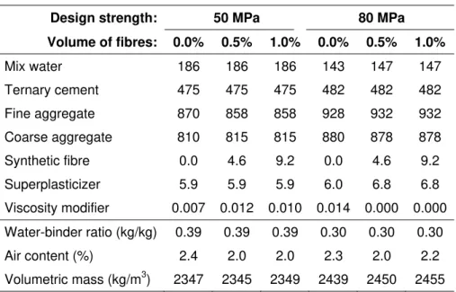
Table 1 indicates the properties of the reinforcing steel and concrete used in each column specimen. The column specimens were designed to offer direct comparisons between sets of specimens with regard to the three selected variables, namely concrete compressive strength (50 MPa and 80 MPa), transverse reinforcement spacing (50 mm and 100 mm) and volume content of synthetic fibres (0.0%, 0.5% and 1.0%). The test specimens are identified by alphanumeric characters related to these test variables; for example, test specimen C50-S100-FP0.5 had a design concrete strength of 50 MPa, a spacing of transverse reinforcement of 100 mm, and a synthetic fibre content of 0.5% by volume of concrete. It should be noted that the concrete compressive strengths obtained on standard cylinders at the time of column testing were significantly higher than the design 28-day compressive strengths, and ranged from 67 to 70 MPa for the C50 concrete and from 82 to 88 MPa for the C80 concrete.
Table 1. Details of test specimens
Column Specimen Longitudinal reinforcement (6 bars, d=20 mm) Transverse reinforcement (spiral, d=10 mm) Concrete ρg (%) fy (MPa) Es (GPa) s (mm) ρs (%) fy (MPa) Es (GPa) f’c (MPa) Ec (MPa) vf (%) C50-S50 2.5 494 220 50 3.5 459 239 70 27,430 0.0 C50-S50-FP0.5 2.5 494 220 50 3.5 459 239 67 26,390 0.5 C50-S50-FP1.0 2.5 494 220 50 3.5 459 239 69 27,250 1.0 C50-S100 2.5 494 220 100 1.7 459 239 70 27,430 0.0 C50-S100-FP0.5 2.5 494 220 100 1.7 459 239 67 26,390 0.5 C50-S100-FP1.0 2.5 494 220 100 1.7 459 239 69 27,250 1.0 C80-S50 2.5 494 220 50 3.5 459 239 88 31,700 0.0 C80-S50-FP0.5 2.5 494 220 50 3.5 459 239 87 32,950 0.5 C80-S50-FP1.0 2.5 494 220 50 3.5 459 239 82 29,270 1.0 C80-S100 2.5 494 220 100 1.7 459 239 88 31,700 0.0 C80-S100-FP0.5 2.5 494 220 100 1.7 459 239 87 32,950 0.5 C80-S100-FP1.0 2.5 494 220 100 1.7 459 239 82 29,270 1.0
2.2 Materials
Table 2 presents the concrete mix designs for the specified concrete strengths of 50 MPa and 80 MPa, and synthetic fibre contents of 0%, 0.5% and 1.0%. The water-binder ratios were 0.39 and 0.30, respectively. Silica fume (5% by mass) and slag (20% by mass) were used with Type 10 Portland cement in all concrete mixes to obtain high strength, workability, and reduction of fine particle segregation. The coarse aggregate was crushed stone with a maximum diameter of 10 mm. Superplasticizer and viscosity-modifying admixtures were used to ensure adequate workability with slumps ≈ 200 mm or slump flows ≈ 600 mm for the placement of fibre-reinforced HSC in confined concrete columns. For each batch of concrete, at least six 150x300 mm concrete cylinders were prepared to determine the stress-strain relationship of unconfined concrete, and compressive strengths at 28 days and time of column testing (which ranged from 111 days to 139 days). The column specimens were cast vertically in plywood forms and consolidated with a needle vibrator. After 24 hours, the forms were taken off and the specimens were wet cured for 2 weeks using wet burlap, after which time the specimens were left in the laboratory at ambient temperature until the time of testing. The synthetic fibres used in this study were made of polypropylene and polyethylene and were shaped by an extrusion process. Each fibre had a length of 50 mm, a rectangular cross-section of 0.05 mm by 1 mm, a density of 920 kg/m3, a tensile strength of 500 MPa and a modulus of elasticity of 4300 MPa (Trottier and Mahoney 2001).
Table 2. Concrete mix formulations (kg/m3)
Design strength: 50 MPa 80 MPa
Volume of fibres: 0.0% 0.5% 1.0% 0.0% 0.5% 1.0% Mix water 186 186 186 143 147 147 Ternary cement 475 475 475 482 482 482 Fine aggregate 870 858 858 928 932 932 Coarse aggregate 810 815 815 880 878 878 Synthetic fibre 0.0 4.6 9.2 0.0 4.6 9.2 Superplasticizer 5.9 5.9 5.9 6.0 6.8 6.8 Viscosity modifier 0.007 0.012 0.010 0.014 0.000 0.000 Water-binder ratio (kg/kg) 0.39 0.39 0.39 0.30 0.30 0.30 Air content (%) 2.4 2.0 2.0 2.3 2.0 2.2 Volumetric mass (kg/m3) 2347 2345 2349 2439 2450 2455 3. TEST RESULTS
Figure 2 presents curves of the column axial load measured as a function of axial displacement for the six C50 columns; Figure 3 presents the same data for the six C80 columns. A typical column behaviour is also explained on Figure 2 using specimen C50-S50-FP1.0 as an example. This typical behaviour consists of 7 different steps, namely: (i) until point A, the load-displacement behaviour is linear; (ii) at point A, microcracks start to form in the concrete cover and continue until the maximum unconfined column capacity is reached; (iii) at point B, the brittle concrete cover begin to spall, resulting in a load reduction; (iv) at point C, spalling of the cover is almost complete, and confinement becomes significant, resulting in an increase in column capacity; (v) at point D, the column reaches its maximum confined capacity and starts unloading gradually as concrete crushes under large deformations; (vi) at point E, a diagonal failure plane has formed, resulting in additional unloading and sliding of the top wedge over the bottom one; and (vii) at point F, the spiral reinforcement collapses, resulting in the sudden buckling of the longitudinal reinforcement and further unloading, which can be considered as the end of the test.
0 500 1000 1500 2000 2500 3000 3500 4000 4500 5000 5500 6000 6500 0 5 10 15 20 25 30 35 40 45 50 Axial displacement (mm) Column a x ial load (kN ) . C50-S50 C50-S100 FP0.0 FP0.5 FP1.0 FP0.0 FP0.5 FP1.0 A B C D E F A: Onset of microcracking B: Onset of cover spalling (1st peak)
C: End of cover spalling / strength gain D: Maximum confined strength (2nd peak) E: End of crushing / onset of shear sliding F: Failure of spiral / buckling of rebars
Figure 2. Axial load vs. axial displacement for test columns with 50 MPa concrete
0 500 1000 1500 2000 2500 3000 3500 4000 4500 5000 5500 6000 6500 0 5 10 15 20 25 30 35 40 45 50 Axial displacement (mm) Column axia l load (kN ) . C80-S50 C80-S100 FP0.0 FP0.5 FP1.0 FP0.0 FP0.5 FP1.0
In general, the 2nd peak can be higher than the 1st peak for columns with adequate confinement; and for columns with low confinement, a strength gain (point D) after cover spalling may not be observed. This is because the small strength increase due to confinement is outweighed by the load reduction due to spalling, especially when there are no fibres to allow a smooth load transfer from the cover to the core. Figure 1 also presents photographs of two C80-S50 specimens after testing, without fibres (left) and with 0.5% fibres (right). The failure plane that formed during the post-peak behaviour is well defined in both columns. The beneficial contribution of synthetic fibres is also illustrated as the cracked concrete cover is still attached to the column (on the right), making it safer for building occupants during earthquakes. In order to assess the effect of the previously-identified test variables on confined concrete, the measured load-displacement behaviour of each column was used to determine the concrete stress-strain behaviour, as follows: (i) the load sustained by the concrete was determined by subtracting from the measured column load the load carried by the longitudinal bars, based on the measured column displacement and the steel constitutive behaviour obtained from tension tests; (ii) the concrete stress before cover spalling at the 1st peak (before point B in Fig. 2) was obtained by dividing the concrete load by the total concrete section (Ac); (iii) the concrete stress after complete spalling (after point C in Fig. 2) was obtained by
dividing the concrete load by the core concrete section (Acc); and (iv) for the portion between points B and
C (during spalling), a gradual transition curve was used to estimate the concrete stress, since the actual concrete cross-sectional area supporting the load when the cover was spalling was not exactly known. Figure 4 presents the axial concrete stress as a function of axial strain for the six C50 columns; Figure 5 presents the same data for the six C80 columns. In general, such as for the three C50-S50 specimens, increasing the volume of synthetic fibres from 0.0% to 0.5% to 1.0% resulted in an increase in the maximum strength of confined concrete and an increase in ductility, which is most likely due to the reduced negative impact of cover spalling on the stress-strain behaviour. There are exceptions, however, to this general trend. For instance, specimen C50-S100-FP1.0 (Figure 4) and specimen C80-S100-FP1.0 (Figure 5) reached lower than expected values of maximum confined concrete strength. In this case, a concrete consolidation problem due to the high fibre content is suspected.
0 20 40 60 80 100 120 0.000 0.005 0.010 0.015 0.020 0.025 0.030 0.035 0.040 0.045 0.050 0.055 0.060 Axial strain Concre te str e ss (M Pa) C50-S50 C50-S100 FP0.0 FP0.5 FP1.0 FP0.0 FP0.5 FP1.0
0 20 40 60 80 100 120 0.000 0.005 0.010 0.015 0.020 0.025 0.030 0.035 0.040 0.045 0.050 0.055 0.060 Axial strain Concrete stress (M Pa) . C80-S50 C80-S100 FP0.0 FP0.5 FP1.0 FP0.0 FP0.5 FP1.0
Figure 5. Axial concrete stress vs. axial strain for test specimens with 80 MPa concrete
Table 3. Main test results
Column Specimen
Axial loads Axial strains
Pmax Pmax Po PC1 PC1 Poc PC2 PC2 Pocc εC1 εC1 εC0 εC2 εC2 εC0 εC50 εC50 εC0 C50-S50 5091 1.02 4218 1.03 3329 1.30 0.0024 0.74 0.0030 0.91 0.0045 1.37 C50-S50-FP0.5 5118 1.06 4228 1.07 3564 1.45 0.0028 0.89 0.0040 1.27 0.0071 2.24 C50-S50-FP1.0 4976 1.02 4087 1.02 3781 1.51 0.0029 0.90 0.0055 1.72 0.0202 6.35 C50-S100 4763 0.95 3877 0.94 3344 1.31 0.0026 0.80 0.0041 1.26 0.0251 7.60 C50-S100-FP0.5 4557 0.94 3419 0.87 3551 1.45 0.0021 0.67 0.0061 1.94 0.0196 6.20 C50-S100-FP1.0 4322 0.88 3441 0.86 3077 1.23 0.0026 0.81 0.0038 1.20 0.0100 3.14 C80-S50 5729 0.95 4862 0.94 3797 1.18 0.0024 0.74 0.0040 1.21 0.0118 3.60 C80-S50-FP0.5 5771 0.97 4884 0.96 4419 1.40 0.0027 0.85 0.0055 1.71 0.0170 5.34 C80-S50-FP1.0 6168 1.09 5279 1.10 4442 1.49 0.0035 1.03 0.0055 1.64 0.0107 3.18 C80-S100 5706 0.94 4833 0.94 3524 1.09 0.0025 0.75 0.0037 1.12 0.0072 2.20 C80-S100-FP0.5 5752 0.97 4899 0.97 4299 1.36 0.0022 0.70 0.0029 0.92 0.0032 1.00 C80-S100-FP1.0 5645 0.99 4758 0.99 4198 1.41 0.0027 0.81 0.0034 1.00 0.0052 1.56
Table 3 presents the main test results of this study. The axial load parameters in the table are: maximum load carried by column (Pmax), maximum load carried by concrete before cover spalls (Pc1), maximum load
carried by confined concrete (Pc2), capacity of column section (Po=0.85f’cAc+fyAst), capacity of total
concrete section (Poc=0.85f’cAc), and capacity of core concrete section delimited by the centre line of the
confining reinforcement (Pocc=0.85f’cAcc). The axial strain parameters are: strain corresponding to Pc1 (εc1),
strain corresponding to Pc2 (εc2), strain corresponding to 0.5 Pc2 on the post-elastic curve (εc50, which is a
measure of ductility) and strain corresponding to f’c measured on unconfined concrete cylinders (εco).
4. ANALYSIS OF RESULTS
Table 4 contains averages of load and strain ratios (Table 3) calculated for each test variable. Table 4. Effects of selected test variables on axial loads and strains
Variable Average axial load ratios
Average axial strain ratios Pmax Po Pc1 Poc Pc2 Pocc εc1 εc0 εc2 εc0 εc50 εc0
Compressive strength 50 MPa 0.98 0.97 1.38 0.80 1.38 4.48
80 MPa 0.99 0.98 1.32 0.81 1.27 2.81 Spiral spacing 50 mm 1.02 1.02 1.39 0.86 1.41 3.68 100 mm 0.95 0.93 1.31 0.76 1.24 3.62 Fibre content 0.0% 0.97 0.96 1.22 0.76 1.13 3.69 0.5% 0.99 0.97 1.42 0.78 1.46 3.70 1.0% 1.00 0.99 1.41 0.89 1.39 3.56
4.1 Spalling of concrete cover
From Table 4, it can be seen that all column specimens achieved their load-carrying capacities, since the values of Pmax/Po ranged from 0.95 to 1.02. The same observation applies to Pc1/Poc, which ranged from
0.96 to 0.99. It should be noted that the three calculated load capacities in Tables 3 and 4 include the 0.85 factor recommended by CSA A23.3 (2004) to account for the size effect on measured strength between standard cylinders and larger columns. These capacities have been recalculated without the 0.85 factor and are presented in Figure 6 along with similar results from large-scale HSC columns previously tested at University of Sherbrooke. It can be seen that the 0.85 factor suggested by CSA A23.3 (2004) overestimates the relative concrete capacity of more than half of the columns, especially when very high strength concrete is used. The guidelines from Norwegian Standard NS 3473 (1989) and Collins et al. (1992) provide conservative predictions for columns with concrete strengths up to 150 MPa.
4.2 Effect of concrete compressive strength
When comparing the average ratios obtained for the six C50 specimens to those of the six C80 specimens, it can be observed that the use of higher strength concrete (from 69 MPa to 86 MPa) did not significantly affect the load and strain ratios at the 1st peak. The use of C80 concrete over the C50 concrete, however, resulted in reduced load and strain ratios at the 2nd peak, with a substantial reduction in ductility (εc50/εco). It is known that confinement is less effective in HSC than in normal concrete since its
Figure 6. Relative concrete capacity of large-size columns as a function of concrete compressive strength
CSA A23.3, 2004
0.50
4.3 Effect of transverse reinforcement spacing
The transverse reinforcement in all columns produced significant confinement, with confined concrete strengths (Pc2) exceeding the unconfined concrete strengths (Pocc) by at least 22% and at most 42%.
When comparing the average ratios obtained for the six specimens with a 50-mm spacing to those with the 100-mm spacing, it can be observed that smaller (and adequate) spiral spacing resulted in substantial increases in load carrying capacity, deformation and ductility. It is known that a closer spacing of the transverse reinforcement can produce lower arching action resulting in a larger area of confined concrete in the column section. Closer spacing can also provide better support for the longitudinal bars.
4.4 Effect of synthetic fibres
In this case, the average ratios were compared between the four columns made with no fibres (FP0.0), the four columns with 0.5% fibres (FP0.5) and the remaining four with 1.0% fibres (FP1.0). At the first peak (onset of cover spalling), the addition of fibres up to 1.0% by volume resulted in marginal increases in the load and strain ratios, at least ensuring that the column capacity is achieved. At the 2nd peak, the load and strain ratios were considerably increased from 1.22 to 1.41 for Pc2/Pocc and from 1.13 to 1.39 for
εc2/εco. These significant increases under large deformations were higher than expected for synthetic
fibres. It is believed that there could be a synergetic effect between the synthetic fibres and the confining steel, in which the synthetic fibres help the transverse reinforcement to confine the concrete more effectively by: (i) delaying the formation of the failure plane after the onset of spalling; and (ii) by distributing the cracks more evenly in the concrete cover. At very large deformations, however, there seems to be no significant improvement in ductility (εc50/εco) due to the fibres alone.
A very interesting finding is that the addition of synthetic fibres in HSC columns can compensate for the reduced confinement from the spiral when the vertical spacing is increased from 50 mm to 100 mm. For the C50 concrete, the three axial strain ratios (i.e. εc1/εco, εc2/εco, εc50/εco in Table 3) were significantly
increased from specimen C50-S50 to specimen C50-S100-FP1.0. For the C80 concrete, on the other hand, the three axial load ratios (i.e. Pmax/Po, Pc1/Poc, Pc2/Pocc in Table 3) were increased from specimen
C80-S50 to specimen C80-S100-FP1.0. For example, at the 2nd peak, Pc2/Pocc increased from 1.18 to
5. SUMMARY AND CONCLUSIONS
An experimental study of the load behaviour and ductility of cylindrical columns made with fibre-reinforced high-strength concrete has been conducted, in which twelve large-size column specimens were built with a length of 1400 mm and a diameter of 300 mm. The investigated variables were: (i) concrete compressive strength (50 MPa and 100 MPa), (ii) transverse reinforcement spacing (50 mm and 100 mm), and (iii) volume of synthetic fibres (0.0%, 0.5% and 1.0%). The following conclusions can be drawn: • The use of higher strength concrete (from 69 to 86 MPa) in spirally confined columns resulted in a
reduction of ductility, as expected. This is due to a higher concrete stiffness, which reduced the effectiveness of the confining reinforcement.
• The use of smaller spiral spacing (from 100 to 50 mm) in the columns resulted in substantial increases in load carrying capacity, deformation and ductility, as expected. The 50 mm spacing provided better support to the longitudinal bars, and increased the cross-sectional area of confined concrete by reducing the arching action.
• The use of up to 1% synthetic fibres by volume of concrete increased the load and strain of the columns at the onset of concrete spalling (1st peak) by 3% and 17%, respectively, compared to identical columns without fibres. This observation shows that the synthetic fibres allowed the columns to reach their expected load carrying capacities at the onset of cover spalling.
• The use of up to 1% synthetic fibres in the columns also resulted in increases in the confined concrete strength (2nd peak) and corresponding strain by 16% and 29%, respectively. This shows that synthetic fibres can help the confining steel to further increase the strength and ductility of columns. • The synthetic fibres did not significantly influence the post-peak behaviour of the concrete columns
under very large deformations.
• The addition of synthetic fibres in HSC columns can compensate for the reduced confinement from the spiral when the vertical spacing is increased from 50 mm to 100 mm.
• Care should be taken to achieve adequate consolidation of fibre-reinforced concrete in heavily confined concrete columns. Higher quantities of superplasticizer and viscosity-modifying admixtures may be required.
6. ACKNOWLEDGEMENTS
The authors would like to acknowledge the financial contribution of the Natural Sciences and Engineering Research Council of Canada. The technical contributions of Laurent Thibodeau, Claude Aubé and Jeason Desmarais were greatly appreciated.
7. REFERENCES
Campione, G. 2002. The Effects of Fibers on Confinement Models for Concrete Columns, Can. J. Civ.
Eng., 29(5), p. 742–750.
Collins, M.P., and Mitchell, D. 1992. Structural Design Considerations for High-Strength Concrete,
Concrete International, 15(5), p. 27-34.
CSA A23.3. 2004. Design of Concrete Structures, 5th Ed., Canadian Standards Association, Rexdale, ON, Canada, 258 p.
Cusson, D., and Paultre, P. 1994. High-Strength Concrete Columns Confined by Rectangular Ties, ASCE
Journal of Structural Engineering, 120(3), March, p. 783–804.
Langlois, Y., and Paultre, P. 2002. Rôle de l’enrobage de béton et effet de la fibre métallique sur le
comportement des poteaux en béton confiné à hautes performances, Report SMS-96/02, Department
of Civil Engineering, University of Sherbrooke, Sherbrooke, QC, Canada.
Nagashima, T., Sugano, S., Kimura, H., and Ichikawa, A. 1992. Monotonic Axial Compression Test on Ultra-High Strength Concrete Tied Columns, Proceedings of Tenth World Conf. on Earthquake
Engrg., Madrid, Spain, July 19-24, A. A. Balkema, Rotterdam, Netherlands, Vol. 5, p. 2983-2988.
NS 3473. 1989. Concrete Structures, Design Rules, Norwegian Standards.